The Apollo Lunar Module (LM /ˈLEM), originally designated the Lunar Excursion Module (LEM), was the lunar lander spacecraft that was flown between lunar orbit and the Moon’s surface during the United States’ Apollo program. It was the first crewed spacecraft to operate exclusively in the airless vacuum of space, and remains the only crewed vehicle to land anywhere beyond Earth.
Everyone called the vehicle the ‘LEM’ throughout most of its development life until May 1966 when a memo from the NASA Project Designation Committee officiously changed the name simply to ‘LM’.
Structurally and aerodynamically incapable of flight through Earth’s atmosphere, the two-stage Lunar Module was ferried to lunar orbit attached to the Apollo command and service module (CSM), about twice its mass. Its crew of two flew the Lunar Module from lunar orbit to the Moon’s surface. During takeoff, the spent descent stage was used as a launch pad for the ascent stage which then flew back to the command module, after which it was also discarded.
In November 1962 Grumman won the contract for the Lunar Module. Overseen by Grumman, the LM’s development was plagued with problems that delayed its first uncrewed flight by about ten months and its first crewed flight by about three months. Regardless, the LM became the most reliable component of the Apollo–Saturn space vehicle. The total cost of the LM for development and the units produced was $21.65 billion in 2016 dollars, adjusting from a nominal total of $2.29 billion using the NASA New Start Inflation Indices. Ten lunar modules were launched into space. Of these, six were landed by humans on the Moon from 1969 to 1972. The first two flown were tests in low Earth orbit: Apollo 5, without a crew; and Apollo 9 with a crew. A third test flight in low lunar orbit was Apollo 10, a dress rehearsal for the first landing, conducted on Apollo 11. The Apollo 13 lunar module functioned as a lifeboat to provide life support and propulsion to keep the crew alive for the trip home, when their CSM was disabled by an oxygen tank explosion en route to the Moon.
The six landed descent stages remain at their landing sites; their corresponding ascent stages crashed into the Moon following use. One ascent stage (Apollo 10’s Snoopy) was discarded in a heliocentric orbit after its descent stage was discarded in lunar orbit. The other three LMs were destroyed during controlled re-entry in the Earth’s atmosphere: the four stages of Apollo 5 and Apollo 9 each re-entered separately, while Apollo 13’s Aquarius re-entered as a unit.
Height: 9 ft 3.5 in (2.832 m) Width: 14 ft 1 in (4.29 m) Depth: 13 ft 3 in (4.04 m) Mass, dry: 4,740 lb (2,150 kg) Mass, gross: 10,300 lb (4,700 kg) Crew cabin volume: 235 cu ft (6.7 m3) Habitable volume: 160 cu ft (4.5 m3) Crew compartment height: 7 ft 8 in (2.34 m) Crew compartment depth: 3 ft 6 in (1.07 m) Atmosphere: 100% oxygen at 4.8 psi (33 kPa) Water: two 42.5 lb (19.3 kg) storage tanks Coolant: 25 pounds (11 kg) of ethylene glycol / water solution Thermal Control: one active water-ice sublimator RCS propellant mass: 633 lb (287 kg) RCS thrusters: Sixteen × 100 lbf (440 N) in four quads RCS propellants: Aerozine 50 fuel / Dinitrogen tetroxide (N2O4) oxidizer RCS specific impulse: 290 s (2.8 km/s) APS propellant mass: 5,187 lb (2,353 kg) stored in two 36-cubic-foot (1.02 m3) propellant tanks APS engine: Bell Aerospace LM Ascent Engine (LMAE) and Rocketdyne LMAE Injectors APS thrust: 3,500 lbf (16,000 N) APS propellants: Aerozine 50 fuel / Dinitrogen Tetroxide oxidizer APS pressurant: Two 6.4 lb (2.9 kg) helium tanks at 3,000 pounds per square inch (21 MPa) APS specific impulse: 311 s (3.05 km/s) APS delta-V: 7,280 ft/s (2,220 m/s) Thrust-to-weight ratio at liftoff: 2.124 (in lunar gravity) Batteries: Two 28–32 volt, 296 ampere hour Silver-zinc batteries; 125 lb (57 kg) each Power: 28 V DC, 115 V 400 Hz AC Crew: 2
With the concept of the convertible helicopter proved on a small scale with the Jet Gyrodyne, the proposal put forward by Dr. J.A.J. Bennett and Captain A.G. Forsyth in 1947 for a large compound helicopter looked viable, and various designs were considered. The first mention of the project and of the name Rotodyne was made in March 1951 by the Ministry of Civil Aviation’s Interdepartmental Helicopter Committee in its initial report. No details were given, but it was reported to have two propeller-turbines and tip-jets, to have a cruising speed of 217km/h and capacity for 23 passengers. This was probably the Mamba-engined project.
Confirmation of the need for such an aircraft was provided by the British European Airways specification of December 1951 for a short/medium-haul ‘BEAline Bus’. Five manufacturers submitted projects to meet this earlier specification for a 30/40-passenger aircraft. Fairey’s original proposal again incorporated the projected D.H. powerplants. These were in two underwing nacelles, in each of which was located a main gas-turbine driving an auxiliary compressor and, mounted in tandem, a second turbine driving a constant-speed propeller through a reduction gear. Air for this turbine was tapped from the auxiliary compressor of the main engine. The rotor was four-bladed, with pressure-jet units at the tips.
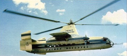
The Gyrodyne had rear clam-shell doors allowing the loading of large motor vehicles. A forward-located door permitted simultaneous entry and exit of passengers. The passenger compartment was 14m long, 2.4m wide, and 1.8m in height. The tail lower tail surfaces were oriented straight down, while the upper surfaces were canted at about a 45 degree angle. The final version, with two Elands driving propellers and/or auxiliary compressors, was outlined in 1953 and formed the subject of a Ministry of Supply research contract. This became the definitive prototype, leading later, without very fundamental changes, to the proposed production Rotodyne FA-1, or Type Z, of 1959-60, with planned seating for up to 70 passengers. For this, XH249 (F.9430), the Elands could not provide the power required, so two 5,250shp Rolls-Royce Tyne propeller-turbines were envisaged. But in hot/high conditions, even this power would have been only just adequate in the engine-failure on take-off case, and Rolls-Royce suggested separate air-producing engines to supply the tip-jets.
Fairey Rotodyne – Eland engines
The proposed solution was to install, at the rear of each nacelle, an RB.176 in which a lightweight gas-turbine drove an auxiliary compressor. By this use of separate propulsion and lift power there would be a considerable increase in weight, but the arrangement gave worthwhile gains in off-design conditions. The Fairey pressure-jet unit for the prototype consisted of a circular-section flame-tube fed by three air pipes and one fuel pipe. This was faired within a streamlined nacelle and terminated in a simple propulsive nozzle. The BEA type specification for the production Rotodyne stipulated an initial climb, at zero forward speed and maximum weight, of not less than 1823m/min, and a noise level, at a distance of 183m, of not more than 96 decibels. With the power planned for the production Rotodyne the noise level for the existing tip-jets would have been about 113 db. To achieve the necessary 17-db reduction in noise level a complete redesign of the pressure-jet was planned. This would have been in two-dimensional form, occupying the last 1.2 metres of each blade, with nine circular flame-tubes in a combustion chamber submerged within the blade profile. Much work was done on silencers, but it was never reduced to the 96 decibels that the authorities demanded.
New test facilities were set up at White Waltham in 1951 for the development of the tip-jets. These consisted initially of a test stand and a rotating rig for chamber-spinning tests. A Rolls-Royce Dart engine, with air tapped from the combustion chambers, was used as a compressor plant for the rig; two other Dart compressor plants were used for the air supply to the rotating stand. On this, a balanced single-bladed rotor, with hingeless hub, was used to investigate tip-jet light-up, regulation, performance, cooling and loads during rotation. Prior to installation on the Jet Gyrodyne, a complete rotor, including hub, blades, jet units and controls, was installed. By the end of 1953 the chamber and rotor had been developed, and the Jet Gyrodyne flew untethered for the first time in January 1954.
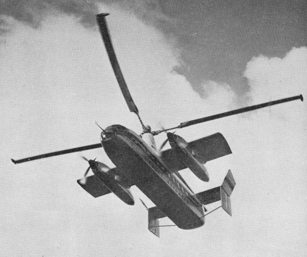
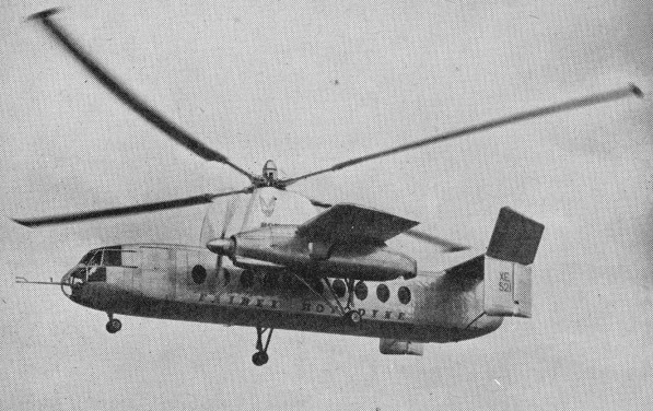
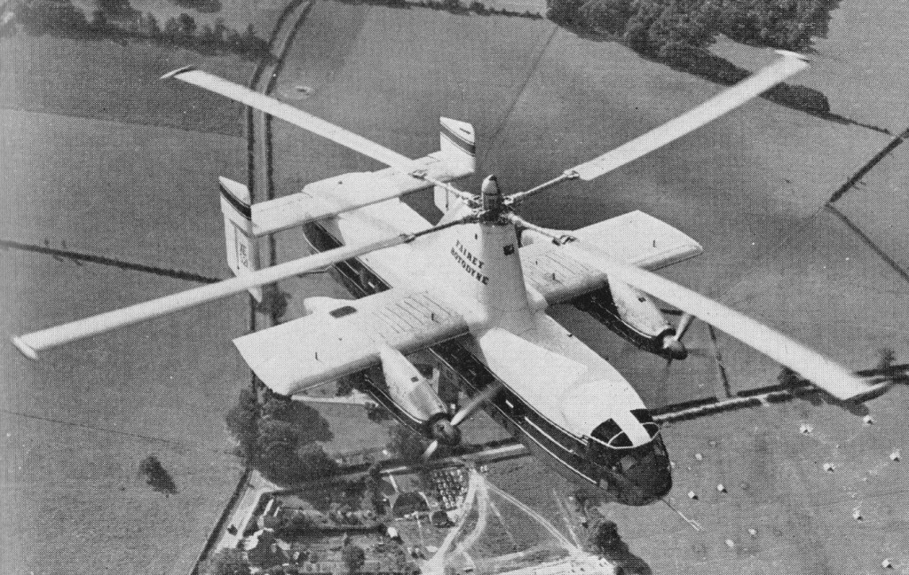
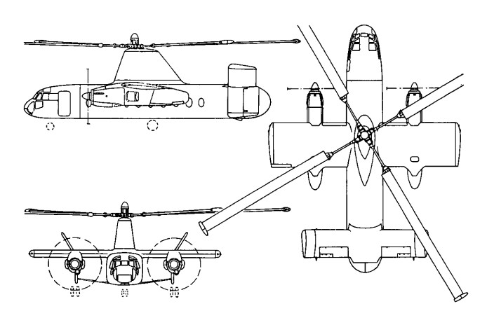
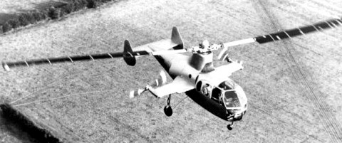
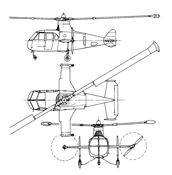
The Rotodyne was a square-section fuselage with untapered 14.17m stub wings on which were mounted two 3000shp Napier Eland turboprops for forward propulsion. The main wheels of the tricycle landing gear retracted forwards into the nacelles, and the nosewheel forwards below the cockpit. Twin fins and rudders, later joined by a central fin, were mounted on an untapered tailplane set on top of the rear fuselage. A large four-bladed rotor for vertical take-off and landing was driven by tip jets which received compressed air from the Eland engines via a compressor. To provide compressed air for the jets the two 2,800shp Napier Eland N.E1.7s operated as dual-purpose powerplants – acting either as normal propeller-turbines or as pressure-generators according to requirements. They were virtually normal Elands up to the rear of the turbine casing, where there was a nine-stage axial compressor driven by the power turbine through an hydraulic clutch. For take-off and landing most of the engine power was absorbed by the compressor, which delivered air to the internal duct system of the rotor. The small amount of remaining power of the engines went to the propellers for yaw control. In cruising flight all the power went to the propellers, with the rotor autorotating. Each engine fed air to two opposing blades so that, in the case of failure of one engine, there would be adequate pressure to keep two jets burning efficiently and giving maximum thrust.
All the earlier flying was completed with the fixed undercarriage while a revised form of retractable undercarriage, with special dampers, was designed and manufactured. This was fitted to the prototype soon after mid-year 1958 when the initial transition trials had been completed and the Rotodyne was being flown faster and for longer periods in the ‘winged autogyro’ mode.
Following the resonance and running tests, the first untethered flight of the Rotodyne, XE521 (F.9429), was made by W. R. Gellatly and J. G. P. Morton at White Waltham on 6 November, 1957, and two further flights, carrying a flight observer, were made on the first day. Originally it had been intended to keep within the ground cushion during the early flights, but the prototype was taken on a circuit of the aerodrome, well above cushion height, on one of the first three flights which were made at a weight close to the 15,000kg maximum.
Until 10 April, 1958, all flights were made in the helicopter mode. On that day, at 1220m, the first transitions were made to and from the autogyro mode and thereafter a stage-by-stage transition technique was further evolved to ensure complete safety at all moments during the manoeuvres. During the 70 earlier helicopter flights, speed had been built up to 250km/h and altitude to 2072m before transition tests were started.
In its original form the control system followed that of the Jet Gyrodyne, with direct roll and fore-and-aft control through the cyclic pitch-change of the rotor-blades; with a trimming ‘elevator’ used to select fuselage attitude (and consequently wing lift) in cruising flight; and with yaw control by differential propeller-pitch at low speeds or when hovering, and by rudders at higher cruise speeds. Early in the test programme it was found that the fore-and-aft attitude control, using the separate functions of cyclic rotor-control and elevator trim, produced some difficulties. The solution was to link the elevator to the longitudinal cyclic control for both slow and high-speed flight and to disconnect the cyclic control when cruising.
Later, when it was found that the economical cruising speed was more like 273km/h than the originally planned 209km/h, it was found that, at higher speeds, the wing was doing too much work and the rotor too little, so that the blades were flapping and the control margins were inadequate. The wing, originally set at an incidence of 4°, was re-set at 0° and fitted with ailerons, the operation of which was linked directly to the cyclic lateral control of the rotor. The outward-sloping upper fins were also moved to the vertical so as to reduce the rolling tendency with yaw. These changes produced a normal ‘aeroplane-type’ rolling control for the pilot, and the situation was further improved later by the fitting of a third upper fin.
Towards the end of 1958 a decision was made to establish a speed record with the Rotodyne. The 100km closed-circuit category was considered to be the most usefully representative of the kind of operation for which the Rotodyne was designed and that in the new convertiplane class (E.2) was chosen. On 5 January, 1959, the Rotodyne was flown by Gellatly and Morton, with Dr D. B. Leason, Fairey powerplant flight observer, and E. J. Blackburn, strain-gauge operator, as ‘passengers’, over a measured circuit between White Waltham and Hungerford, Berkshire. The flight was completed at an average speed of 307km/h – which was 79km/h higher than the equivalent record for a helicopter and nearly 48km/h higher than that for absolute speed in a straight line. At that time the Rotodyne had not yet been modified with the reduced wing-incidence and the fitting of ailerons to improve control at higher speeds. The record, which was confirmed in March, stood until October 1961, when it was beaten by the Russian twin-rotor Kamov Ka-22 Vintokryl convertiplane.
On 16 June, 1959, the Rotodyne was taken outside the United Kingdom for the first time when it was flown to Paris for the 23rd Aeronautical Salon from London’s Heathrow Airport, via the Allee Verte heliport at Brussels and the Issy heliport in Paris before landing at Le Bourget. After demonstrations there, and at Versailles for officers of the North Atlantic Treaty Organization, the Rotodyne was flown back to Heathrow.
During 1959 the wings were given ailerons and increased incidence, and the vertical tail surfaces were also revised. On 7 February 1960, XE521 resumed trials with an added central fin, shortened exhausts and a fully-faired rotor pylon.
Budgetary problems of the time saw the RAF and British Army withdraw their interest and the Rotodyne became a wholly civil project.
During 1958 the Kaman Aircraft Corporation secured a licensing agreement for sales and service in the USA with a possibility of manufacture there. Okanagan Helicopters of Vancouver was interested in three and Japan Air Lines was considering the type for domestic routes. However, the biggest potential customer was New York Airways, which joined with Kaman in a letter of intent for five, plus options on 10, for delivery in 1964. The provisional order from NYA was for the bigger-capacity, 54/65-seat Rotodyne powered with Rolls-Royce Tyne propeller-turbines and with a gross weight of 22680kg. There had been earlier references to the use of Tynes in the production version, but this order led to the first fuller statements about this version, for the development of which an additional GBP8-10 million was needed. The Government had offered to contribute half this sum, up to a certain fixed maximum, with repayment through a sales levy, but this was conditional on a firm order from BEA. Confirmation of the NYA order depended on several factors — including one that the first ‘Mk.2’ Rotodyne should be flying on test by the autumn of 1961 and another that the noise-level should be acceptable to the airline and airport authorities.
At the Paris Salon in June 1959 a model of the production version had been exhibited in the markings of New York Airways.
Fairey needed up to GBP 10 million to develop this version and was offered 50% of this by the government if BEA would place a firm order. The government contribution was to be a loan, repayable by a sales levy. In 1960 Fairey merged with Westland and although initially the Rotodyne project looked secure, it was not. In April 1960 Okanagan cancelled its order because of the long delivery dates, and five months later New York Airways expressed concern over the delay in production plans. Westland was then involved in taking over Bristol’s helicopter programme as well as with other work in hand. This, together with the ever-increasing weight of the Rotodyne, which reached a stage where the Eland could no longer be developed and the Tyne could not be afforded, led to withdrawal of government support, and the project was cancelled on 26 February 1962. On that date the British Minister of Aviation, Mr Peter Thorneycroft, said that, because of the costs involved, it was necessary to ‘forego the operational advantages’ offered by the military version, and that British European Airways, then its only potential British civil operator, had regretfully concluded that ‘the commercial prospects on their routes were not sufficiently assured to justify the heavy liabilities involved’ in placing a production order. In the absence of any firm order, Westland Aircraft did not feel justified in proceeding with the project. GBP11 million was spent during the nine years or so following the placing of the original research contract in July 1953. During the final three years of the period, however, financial support had been uncertain and the project suffered from continuing political and other indecisions which made costly forward planning impossible. The Rotodyne was subjected to a vigorous flight test program of over 350 flights, more than half of them demonstrating 200 hover-to-vertical flight transitions.
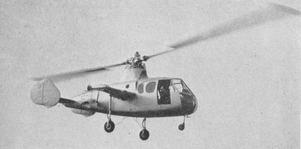
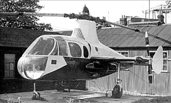
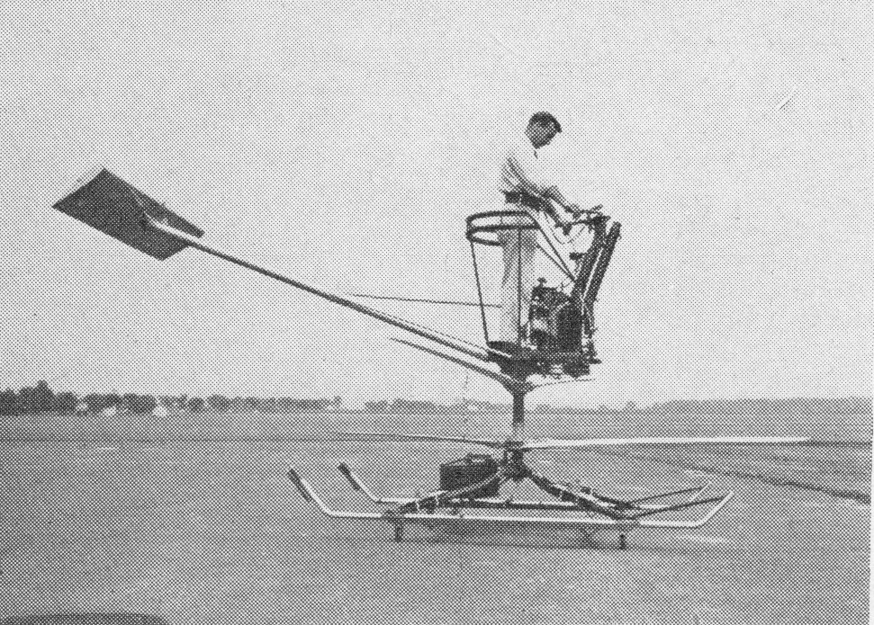
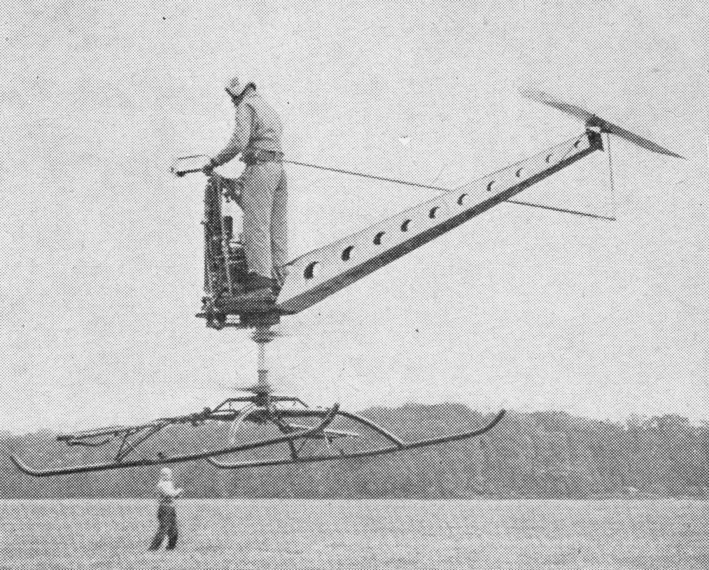
Towards the end of 1953 the surviving second prototype Gyrodyne reappeared in a very different form. A research contract had been received from the Ministry of Supply to try the principles of the tip-jet rotor-driving system.
This was necessary to test the tip-jet, and to develop handling and other procedures for the compound, or convertible, helicopter. By early January 1954 this aircraft, named the Jet Gyrodyne, and carrying the duplicated Ministry serial XD759, which was later to be changed to XJ389, was making tethered flights at White Waltham in the hands of John N. Dennis, who had joined Fairey as helicopter test pilot in June 1949. The first free flight was made in January 1950.
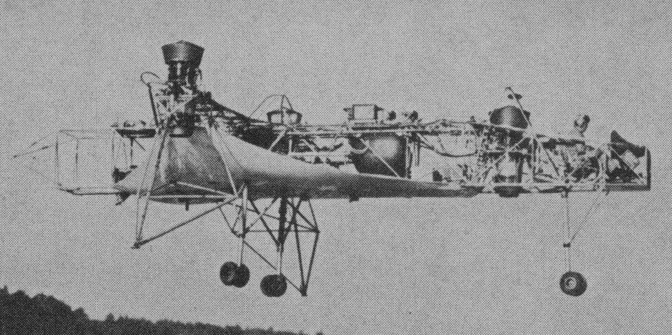
The Jet Gyrodyne retained the fuselage, tail unit, stub wings and tricycle undercarriage of the Gyrodyne, and was also powered by a specially modified Alvis Leonides nine-cylinder radial. The engine was used to drive, through a gearbox and shafts in the stub-wings, two variable-pitch pusher propellers of Fairey design. These propellers provided propulsion in cruising flight and slow-speed directional control through rudder pedals by means of a differential pitch-change which was superimposed on the collective-pitch action. A third drive from the Leonides was taken from the main gearbox, via a friction clutch, to two Rolls-Royce Merlin centrifugal compressors mounted face-to-face under the rotor pylon. Air from these compressors was fed to the fuel-burning pressure-jet units at the tips of the 18.29m two-blade rotor. Unlike that of the Gyrodyne, the rotor had a conventional helicopter control system – with collective-pitch change for varying the overall lift, and cyclic alterations of the blade-angle, by means of a conventional column, to provide fore-and-aft and lateral, or rolling, control.
In the Jet Gyrodyne tip burners, compressed-air from the blowers passed through the rotor blades, while centrifugal force fed the metered fuel through the blades to the jets. The compound, or convertible, helicopter principle is lift for take-off, slow flight and landing was provided by the jet-driven rotor. For transition to cruising flight the compressed air to the rotor tips was progressively reduced and available engine power transferred to the propellers, leaving the rotor as an auto-rotating lift unit which was supplemented (in a very minor proportion for the Jet Gyrodyne) by the fixed wing. The procedure was reversed for a return to the helicopter regime.
The problem for the Jet Gyrodyne was accentuated by, at a gross weight of 2720kg, under-powered for the work it had to perform and the Leonides was normally operated at maximum boost. The Jet Gyrodyne could not quite maintain level flight in the cruising, autorotative, mode. It was not until 1 March, 1955, that a transition was completed by John Dennis. Within four months of this first full transition, the techniques had become well established and transition was no longer being accompanied by a considerable loss of height. The cycle was demonstrated during the SBAC Display at Farnborough in September 1955; while practicing for this demonstration, 65 successful in-flight tip-jet re-lights were accomplished during eight days.
Even during the earlier period of testing, the transition from helicopter to autogyro flight was relatively easy. The basis of the operation was the transfer of engine power from the jet-feeding compressors to the propellers. The pitch of the propellers was progressively coarsened, thus absorbing more power and reducing the air delivery to the jets, which eventually flamed out, and the compressors were declutched. It was found that transition could be made at widely varying speeds, but 128km/h was found to be the most convenient, with a rotor speed of about 210 rpm.
The difficult operation was the transition back to helicopter flight. A great deal of flying was required before the best propeller-pitch and tip-jet re-lighting sequence could be established. A major part of the difficulty was that, with the compressors being driven, there was no reserve of engine power for the propellers during the re-lighting sequence, and the aircraft descended rapidly in autorotation until the jets had been re-lit. So long as the re-lighting was being done over or near an aerodrome there was no particular danger in this situation; a controlled landing could be made, and often was made, in autorotation.
As finally established, the drill was to throttle back momentarily, engage the compressor clutch, switch on the tip-jet ignition and fuel supply, and progressively fine-off the propeller pitch. This automatically opened the intake-valves for the compressors. The tip-jets re-lit when a certain head pressure had been reached and collective-pitch was increased to keep the rotor speed down. Propeller pitch was then slowly reduced to zero so that maximum power was available for the blowers to give full tip-jet thrust.
Because of the need to keep the gross weight down with the limited power available, the Jet Gyrodyne normally carried only sufficient fuel for 15 minutes or so of safe tip-jet burning endurance. Extra tanks were occasionally carried under the wings to provide 30 minutes’ endurance, but, as already noted, there was no particular danger in fuel exhaustion for an aircraft which could make powerless autorotative landings from a best indicated gliding speed of only 72km/h. The high inertia of the big rotor allowed for a few moments of hovering before touch-down.
By September 1956 the Jet Gyrodyne had made 190 transitions and 140 autorotative landings. The techniques were by then familiar and reasonably well understood, so that there was already a sound basis for the procedures required for the Rotodyne, which was to make its first flight a year later.
All the early test flying with the Jet Gyrodyne, including transition from helicopter to autogyro flight and vice versa in March 1955, was done by John N. Dennis. Six Ministry of Supply pilots each flew the Jet Gyrodyne successfully after about an hour’s instruction and practice.
At the time when the Jet Gyrodyne was making its earlier test flights the design team was led by Dr G. S. Hislop, chief designer (helicopters), and Capt A. G. Forsyth, chief helicopter engineer, who was responsible, among other features, for the tip-jets, and shared with Dr J. A. J. Bennett (who had by then left the company) the 1949 British Patent on which the Jet Gyrodyne and Rotodyne concepts were based. Later Jet Gyrodyne flight development was carried out by Sqn Ldr W. R. Gellatly and Lt Cdr J. G. P. Morton, who were to take the Rotodyne through its four years of testing.
Although scheduled for scrapping in 1961, the Jet Gyrodyne was rescued and eventually preserved.
In 1959 the design teams of the German companies Bolkow, Heinkel and Messerschmitt were formed into a consortium named Entwicklungsring Sud to develop a Mach 2 VTOL interceptor for the Federal German defence ministry. Heinkel left the consortium in 1964 and in the following year it was re-formed as a company with the title Entwicklungsring Sud GmbH, EWR.
115 foreign companies’ participed including 35 in England, 60 in the US and 20 in France. A test rig built had three 2200 lb thrust Rolls-Royce engines installed in the same geometric arrangement as the VJ-101. Latter two 2759 lb thrust Rolls-Royce RB 145s in each of the two wing tip pods plus another two installed vertically in the fuselage were installed.
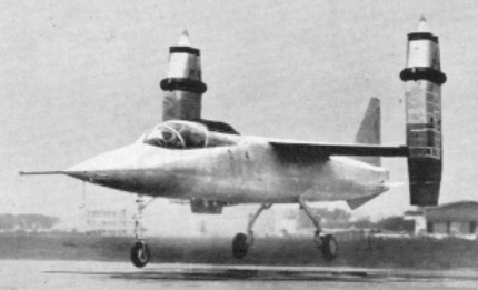
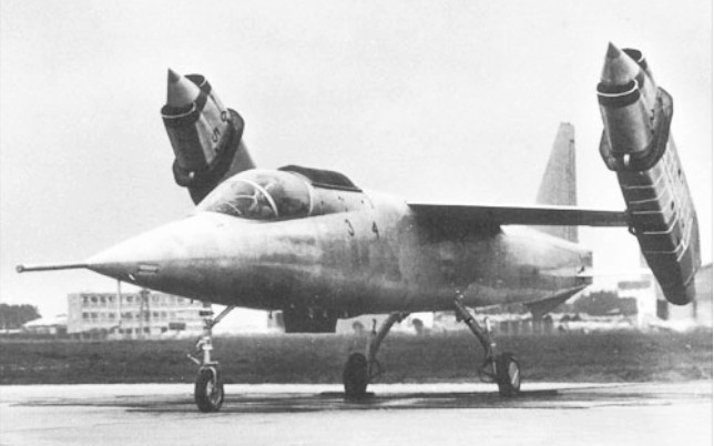
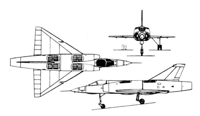
Two prototypes of the EWR VJ 101C single-seat experimental VTOL aircraft were built. Generally similar, they were both of high-wing monoplane configuration, primarily of light alloy construction, had retractable tricycle landing gear and accommodated the pilot in a pressurised cockpit, seated on a Martin-Baker ejection seat. Powerplant comprised six 2750-lb (1247-kg) thrust RB.145 turbojets, developed jointly by Rolls-Royce and MAN-Turbomotoren, with two mounted vertically in the fuselage, immediately aft of the cockpit, and two in a swivelling pod at each wingtip.
Those in the fuselage were used only for VTOL and low-speed flight, those in the wingtip pods for VTOL, low speed, transition from vertical to horizontal flight, and high-speed flight. Control of the aircraft in flight had been explored by a hovering rig powered by three Rolls-Royce RB.108 lift-jets, and by May 1963 this had made a total of 70 flights.
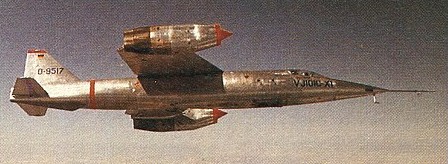
The VJ 101C X-1 prototype was flown for the first time in free hovering flight on 10 April 1963. It had exceeded a speed of Mach 1 several times before it crashed, following a vertical take-off, on 14 September 1964.
The VJ 101C X-2 differed by having afterburning engines in the wingtip pods, providing greater power (3550-lb / 1610-kg) for take-off and landing, and this made its first hovering flight on 12 June 1965. Four months later, on 22 October, the X-2 achieved the first full transitions from vertical to horizontal flight and vice versa, but development was discontinued soon after.
In absence of support by US Defence department or private manufacturers, the German government indicated in 1964 it won’t continue with a production version. Flight tests of the VJ.101C, including low supersonic advancement with afterburners fitted to the RB.145 engines, was continuing.
Production of a single-seat interceptor was planned, under the designation EWR VJ 101D, but this would have differed considerably from the research prototypes. VTOL lift would have been retained by a battery of Rolls-Royce/ MAN RB.162 lift-jets in the fuselage, but primary propulsion would have come from two Rolls-Royce/MAN RB.153 turbofans mounted in the rear fuselage, these relying upon thrust deflection for control purposes. None of these aircraft was built.
EWR VJ 101C X-1 Engines; 6 x Rolls-Royce/MAN RB.145, 1247kg / 2750-lb Max take-off weight; 6000 kg / 13228 lb Wingspan; 6.61 m / 21 ft 8 in Length; 15.70 m / 51 ft 6 in Height; 4.13 m / 13 ft 7 in Max. speed; 1.08M Crew; 1
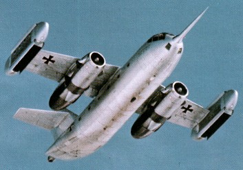
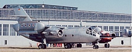
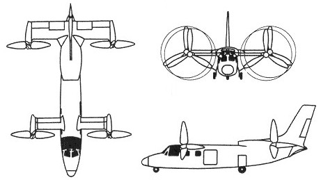
In 1962, the German Federal Ministry of Defense awarded Dornier a design contract for the Do 31 V/STOL transport aircraft. Under this experimental program, the production program covered a small and a large hovering rig for studying design principles, an airframe for structural testing, and a systems test stand for hydraulic and electric systems. Two prototypes were built and a third airframe was completed for static tests. The Do 31 E-1 was equipped with two engines providing power for cruising flight as well as lift during takeoff and landing via vectored nozzles. To support the cruise engines in hover flight another eight engines were installed in nacelles at the wing ends. By tilting the cruise engine nozzles, the Do 31 was accelerated to the speed of approximately 250kph required for aerodynamic horizontal flight, and the eight lift-producing engines were stopped again after 20 seconds. In the two prototypes, the main cabin was occupied by test equipment, but the fuselage volume of 1,765 cu ft (50.0 cu.m) would be equivalent, in a production version, to accommodation for 36 people. The Do 31 E was preceded by a small flying bedstead test rig, which in its one year’s flying made 247 test flights with nine different pilots; and then, in January 1967, by a larger rig which immediately preceded the first flight of the Do 31 E1 on 10 February 1967.
The first Do 31E1 first flew on 10 February 1967 with two Pegasus vectored-thrust turbofans in underwing nacelles and two removable wingtip pods each containing four 4400-lb (1996-kg) thrust RB.162 turbojets. During its three year test programme, the Do 31 investigated problems associ¬ated with all weather flying and opera¬tional noise levels, as well as those con¬cerned with VTOL operation. The Do 31, which established several world records during its ferry flight to the 1969 Paris Air Show. The Do 31 E concluded its test flying programme in April 1970, exactly six years after Dornier’s first little test rig made its original flight.
Do-31 E3 Engines: Two 15.500 lb (7,000 kg) st Rolls Royce Bristol Pegasus 5 2 vectored thrust turbofan for propulsion, plus eight 4,400 lb (2.000 kg) st Rolls Royce RB.162 4D lift jets in wing tip pods. Wing span: 59 ft 3 in (18.06 m). Length: 68 ft 6 in (20.88 m). Height: 8.53 m / 27 ft 12 in Wing area: 57.0 sq.m / 613.54 sq ft Gross weight: 60,500 lb (27,500 kg). Empty weight: 22453 kg / 49501 lb Max. cruising speed: 400 mph (650 km/h) at 20,000 ft (6,000 m). Ceiling: 10515 m / 34500 ft Accommodation: up to 36 fully equipped troops. Crew: 2
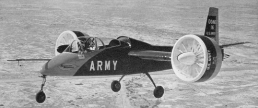
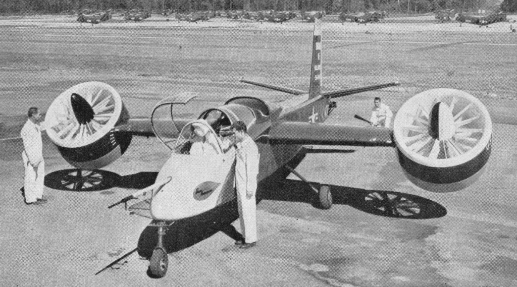
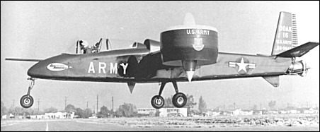
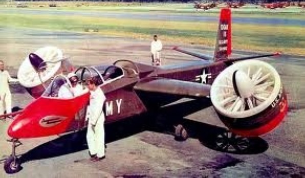
Company president, Edmond R. Doak, had experimented with ducted fan and various other air moving principles since 1935. He first proposed a VTOL aircraft using the tilt duct principle to the military as early as 1950. The Army issued the contract to Doak on April 10, 1956. The U.S. Army Transportation Research and Engineering Command purchased a single Doak 16. The Model 16 made its first flight in February 1958 and the single prototype was put through extensive pre-delivery flight testing and was not officially accepted by the Army until September 1959. Upon acceptance the craft, which had already been allocated the serial number 56-9642, was given the designation VZ-4.
Early 1958
Doak Model 16 was the first VTOL aircraft to demonstrate the tilt duct concept. It was built by the Doak Aircraft Company of Torrance, CA. The fuselage was constructed of welded steel tubing covered by moulded fiberglass skin from the cockpit forward, while the wings and tail were metal-skinned. The aircraft was designed to accommodate a pilot and observer sitting in tandem, though as far as can be determined the observer’s seat was never actually installed in the prototype. With a mid-wing, conventional tail, and fixed tricycle landing gear, a single 1000shp Lycoming YT53-L-1 turbine mounted in the fuselage just aft of the cockpit drove two ducted-fan airscrews, one fixed within each rotating wingtip fan assembly. The fans were set in the vertical position for takeoff and landing, and were rotated into the horizontal plane for normal forward flight. Some additional directional stability was provided by routing the turbine exhaust through a set of hinged louvers mounted in the aircraft’s tail. The cantilever wing and tail unit were of all metal construction. To save development costs, Doak incorporated numerous off the shelf items in the design, such as the landing gear from a Cessna 182, seats from a F-51, duct actuators from T-33 electric flap motors, and the rudder mechanism from an earlier Doak aircraft.
The design empty weight was 900kg with a design gross vertical take-off weight of 1170kg. These grew to 1037kg and 1443kg during the life of the program. To keep weight down, the original specification called for the aircraft fuselage to remain uncovered. However, it subsequently was felt that this would severely limit being able to obtain any meaningful forward speed data, and that the added weight would allow for much more valuable data to be collected.
The wingtip-mounted ducts were five feet in diameter with a four foot inside diameter. Their construction was of aluminum alloy with a fiberglass leading edge section. Eight fixed pitch fiberglass fan blades turned at a maximum fan speed of 4800 rpm. Ahead of the fan in the forward part of the duct were fourteen fiberglass variable inlet guide vanes. The vane angle varied during hover to modulate the thrust produced by the duct, and thus to obtain roll control. The prop was set back two feet from the front of the duct to prevent airflow separation. Nine stainless steel stator blades located aft of the fan straightened the air flow as it exited the duct. The ducts rotated through 92 degrees, pointing horizontal for forward flight, and pivoting to 2 degrees aft of vertical during hover. The ducts rotated past vertical to compensate for the thrust from the jet exhaust. A switch on the control column initiated the duct rotation. To power the fans, drive shafts traveled through the wing quarter chord. Doak-designed flexible couplings compensated for misalignment and wing flexing.
A Lycoming T-53-L-1 turboshaft engine located in the fuselage just below the wing root provided power. It produced 825hp (some sources stated 840hp). A “T” box on the engine transmitted power to the ducts using a four-inch tubular aluminum shaft and two smaller steel shafts of 3.8cm each. Flight controls consisted of standard stick and rudder. An electrical and mechanical interlock system controlled all functions for both hovering and forward flight. There were no other cockpit controls. In hover, a cruciform shaped vane in the tail pipe at the rear of the fuselage controlled pitch and yaw by deflecting the engine exhaust. Rotating the inlet guide vanes in the ducts provided roll control by restricting airflow. As the ducts rotated from vertical to horizontal, a mechanical control system gradually phased out control of the inlet guide vanes and left them aligned with the duct airflow. There was no artificial damping or power boost. Doak looked down on any type of automatic stabilization system, feeling that the aircraft should be a satisfactory flying machine without any such equipment. Careful selection of the duct location allowed the fuselage to remain level throughout the transition. Ground testing began at Torrance Municipal Airport during February 1958. Tests consisted of 32 hours in a test stand, and 18 hours of tethered hovering and taxi tests. The first free hovering flight was performed on February 25 1958. Initial Doak testing at Torrance was completed in June 1958 and was followed by a complete tear down inspection. The aircraft then was transferred to Edwards AFB in October 1958. At Edwards, it performed 50 hours of tests, including transitions at altitudes as great as 1830m. James B. Reichert completed the first conversions in 1959. Following these tests, the Army accepted the Doak 16 in September 1959 and transferred it to NASA Langley for further tests. In 1961 Douglas Aircraft Co. purchased the design rights and test data on the VZ 4. Douglas liked the aircraft and had some ideas for improving it, primarily by installing a larger engine and making numerous structural improvements. They made an unsolicited proposal to the Army in 1961, but could not sell their ideas. The Doak 16 remained at NASA Langley until August of 1972. Eventually it was transferred to the U.S. Army Transportation Command Museum at Fort Eustis, VA, near Newport News, where it is on display.
VZ-4 Engine: 1 x Lycoming YT53, 625kW / 800 hp Wingspan: 7.77m Length: 9.75m Height: 3m Wing area: 8.73sq.m Empty weight: 900-1037 kg Max take-off weight: 1170-1443kg Max speed: 370km/h est. Rate of climb SL: 30m/s Hover ceiling: 1830m Endurance: 1 hr Range: 370km Crew: 2
The flying platforms grew out of research conduction by the US National Advisory Committee on Aeronautics in the early 1950s on the feasibility of one-man flying platforms for combat use. The tests involved pilots “flying” tethered platforms, at first lifted by compressed air, and then by rotors.
The concepts investigated in the tests were based on thinking by NACA engineer Charles H. Zimmerman, who proposed that if the rotors of a helicopter were placed on the bottom of the aircraft, a pilot would be able to steer it just by shifting his or her weight, a concept Zimmerman called “kinesthetic control”. It was hoped that kinesthetic control would allow a pilot to fly such platforms with little training. The tests demonstrated the technical validity of the concept. The NACA results were released to the public, resulting in flying platform prototypes from three companies: de Lackner, Bensen, and Hiller.
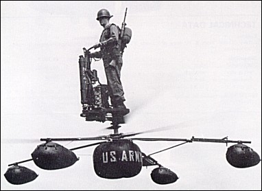
de Lackner company privately developed a rotorcraft named the “DH-4 Helivector”, later renamed the HZ-1 Aerocycle. The de Lackner machine consisted of a frame that supported the engine of a 30 kW (40 HP) Mercury outboard motor, with landing gear consisting of an arrangement of airbags on the ends of spars. The airbags were later replaced by metal skids. The engine drove a pair of 4.6 meter (15 foot) contra-rotating rotors directly beneath it, while the pilot stood vertically on a platform above the engine, protected from falling into the rotors by a safety harness, and hanging on motorcycle handlebars with it a twist-grip throttle. He used kinesthetic control to fly the machine.
Aerocycle, 1958
The Helivector / Aerocycle first flew in January 1955, and the Army ordered twelve examples ‘off-the-shelf’ shortly after. The aircraft was initially designated YHO-2 (a designation which was later also applied to five Hughes H-55 helicopter prototypes), though this was subsequently changed to HZ-1. De Lackner claimed the machines could fly at up to 105 kph (65 mph), carry up to 55 kilograms (120 pounds) payload besides the pilot, and fly for an hour. However, while the thing looked like it would have been a lot of fun to fly, it was also dangerous. Not only did the pilot stand above the whirling rotors, but the rotors were wide and close to the ground, making them a hazard on landings and takeoffs since they could easily kick up rocks and other debris.
The Aerocycle carried its single pilot and 32kW engine on a circular platform located just above two belt-driven, contra-rotating fifteen-foot propellers. The engine throttle and a few basic instruments were attached to bicycle-type handlebars fixed to a three-foot tall pedestal atop the main platform. The pilot stood to the rear of the pedestal and was secured to it by safety belts, and guided his craft by simply leaning in the desired direction of travel. The machine’s landing gear initially consisted of a single large air bag placed directly beneath the propellers and augmented by four smaller air bags fixed to outrigger bars, though this system was ultimately abandoned in favor of helicopter-type metal skids. The HZ-1 was surprisingly stable despite its appearance, and its top speed of more than 110kph made it considerably faster than most of the other unconventional one-man flying machines evaluated by the Army.
The Army’s research was to explore the feasibility of inexpensive, safe, and easily operated personal aircraft. The Aerocycle was especially successful in the ease of operation category, for during the service tests soldiers required only about twenty minutes of instruction before flying the aircraft.
Under test at the Forrestal Research Centre
Some sources claim that the Helivector / Aerocycle was easy to fly, others state that the test pilot insisted that novices could not pilot it safely. After two flight accidents in which the contra-rotating rotors flexed and collided, the project was abandoned as impractical. At least one survives as a museum display.
De Lackner HZ-1 Engine: 1 x Kieckhaefer Mercury Mark 55, 32kW Main rotor diameter: 4.57m Height: 2.13m Take-off weight: 206kg Empty weight: 78kg Max speed: 120km/h Cruising speed: 90km/h Service ceiling: 1520m Range: 24km Crew: 1
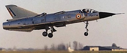
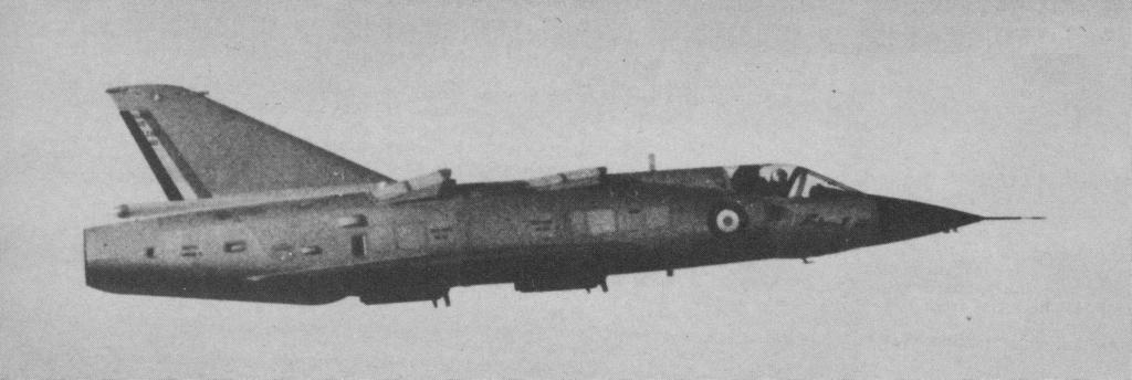
Dassault started work on vertical take-off and landing (VTOL) at the beginning of the 1960s and elected to modify the original Mirage III-001 prototype for VTOL research. This used the cockpit, wings and vertical tail of the Mirage III married to a similar but new fuselage containing a 4850-lb (2200-kg) thrust Bristol Orpheus turbojet for forward propulsion and eight 2160-lb (980-kg) thrust Rolls-Royce RB.108 turbojets mounted vertically for direct lift. These were installed in four groups of two on each side of the centreline fore and aft of the centre of gravity. These lift engines featured retractable intake grilles and the exhausts were covered by fairing doors during normal forward flight.
After tethered hovering trials, the Balzac – as it was renamed – made its first free hovering flight on October 13, 1962 and its first transition on March 18, 1963.
Its career was interrupted by a crash landing on January 10, 1964 but it was subsequently repaired and flew again by the next August. The Balzac provided Dassault with a great deal of information on stabilization in hovering flight and led to the Mirage III-V.
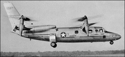
The Curtiss-Wright X-19 began as a commercial venture to develop a small, 4-passenger, executive VTOL aircraft that would have good high speed performance. Funded initially by Curtiss-Wright, it was designated the M-200. With solid test results from the X-100 confirming their theories regarding the potential for a practical application of radial lift, Curtiss-Wright pressed on with the design of the M-200. Design trade-off studies were performed which ultimately led to the X-19’s tandem wing configuration with a tilting propeller at each wing tip. The X-19 started with what Curtiss-Wright engineers felt was the optimal design for a propeller for a VTOL aircraft and then built the aircraft around it. The propellers had a very wide chord with a large amount of twist. This allowed them to maximize the amount of radial lift. At the start of the program, Curtiss-Wright funded the entire effort, with no interest in any government support. Two prototypes were being built when new management at Curtiss-Wright decided they no longer wanted to invest company research funds. They offered the two aircraft to the Tri-Service VTOL Program, a joint Air Force, Army, and Navy program office tasked with developing VTOL technologies for military needs. The Tri-Service Program also was developing the XC-142 and the X-22. Eighteen months later the Air Force agreed to buy the aircraft. When the Tri-Service Program bought the X-19s, the two prototypes already were 55 percent and 35 percent complete, with a substantial investment already having been made by Curtiss-Wright. The original X-19 design, as the M-200, was not built to any specific mission requirement. The goal was to fly as fast and far as possible and to be economically competitive with conventional executive transports that were becoming very popular in the 1960s. Analysis of the design showed that the M-200 could achieve a range of 1450km to 1850km with a maximum level speed of 740km/h at 4880m. It was to conform to FAA regulations, have all weather flying capability, low noise level, and be free of vibration. Conventional aircraft construction techniques and materials were used.
The X-19’s basic configuration was an all-metal, monocoque fuselage, with two shoulder-mounted tandem wings. A nacelle at each wing tip could rotate from pointing vertically for take off and landing to pointing horizontally for cruise. The wide, specially-designed propeller was mounted in front of each nacelle. Two turboshaft engines housed in the rear fuselage powered the four props. The fully hydraulic tricycle landing gear retracted completely into the fuselage. A large vertical tail was required because the props were located relatively close to the fuselage. Total height was just over 5m. The original fuselage was 12.5m long, but the cabin area was only 1.2m high, 1.4m wide, and 2.4m long. The passenger compartment was intended for four passengers, or 450kg of cargo. The cabin was pressurized to 4880m. All fuel was stored in the fuselage, aft of the passenger/cargo area. There were two 860 lt tanks and one 990 lt tank. The front wing had a 6.1m span with a narrow chord, while the rear wing had a 6.4m span with a greater chord. The rear wing had almost twice the area of the front wing. The wings had no incidence, dihedral, or sweepback. The front wing incorporated full span flaps, while the rear wing had inboard ailerons and outboard elevators, the ailerons being slightly larger than the elevators. The flaps on the front wing were directly coupled to the nacelle tilt angle, and the pilot could not control them independently. At hover, the flaps and elevators drooped to their full extension of 60 degrees to decrease the amount of wing area that was in the prop downwash. The location of the props on wing tips, however, resulted in the loss of 7 to 9 percent of lift due to wing interference. Curtiss-Wright intended originally to use four Wankel rotary engines rated at 580hp each. Curtiss-Wright eventually abandoned the Wankel in favor of two Lycoming T-55-5 turboshaft engines of 2200hp each (although some sources stated T-55-L-7 engines of 2650hp each). This more than doubled the total power, but retained the ability to operate with one engine failed, including performing vertical take-offs and landings. Switching from four engines to two also simplified the design by decreasing the engine interconnects, and changing to turboshaft engines eliminated the need for engine cooling. Power from the engines was distributed to the props by means of three-inch diameter drive shafts and seven gear boxes. The gear boxes consisted of one engine coupling box that coupled the two engines so that either could power the entire system, two T-boxes to transfer power from the fuselage shafts into the wing shafts, and four nacelle tilt gear boxes. The exhaust pipe from each engine joined in the fuselage so that only one pipe exited the rear of the aircraft. The 4m diameter props construction consisted of a steel shank, foam core, and fiberglass shell. The paddle-wheel shape allowed them to produce about 2.7kg of thrust per horsepower. Low prop noise was obtained because the maximum tip speed of 250m/s was well below sonic speed. The cockpit accommodated two pilots seated side by side. The aircraft could be flown from either seat, but the pilot-in-command seat was on the right, as in a helicopter. The cockpit resembled that of a conventional aircraft, with the cockpit visibility being very limited for a VTOL aircraft. The high instrument panel also restricted vision over the nose. Two one-foot square windows were located near the pilots’ feet, but were too small to be effective and later were modified into ram air inlets to provide additional cooling. Each pilot had a conventional stick, rudder pedal, and two throttles. Nose wheel steering was by means of a hand tiller controlled by the copilot. To minimize the clutter on the instrument panel, there was a single oil temperature gauge and single oil pressure gauge for all nine gear boxes. The pilot could select which component to monitor by rotating a 9-way selector switch to the desired component. To signal a problem, each gear box had a single warning light that indicated either high or low oil pressure, or the presence of metallic chips in the oil. If the light illuminated, the pilot had to rotate the 9-way switch to see the specific problem. When rotated to the vertical positions, the front nacelles rotated past vertical, to 97 degrees, meaning the thrust actually pointed slightly forward. The rear naceltes rotated only to 82 degrees with their thrust pointing slightly rearward. A tilt button on the control stick caused all nacelles to tilt together. Initially, the nacelle tilt rate was mechanized at 5 degrees per second. It was soon realized that this would have required a deceleration from 90km/h to hover in less than 5 seconds, resulting in 0.5g of longitudinal acceleration. This was too much, so the rate was reduced to 1 degree per second, resulting in a more reasonable 0.2g. Two independent hydraulic systems controlled the nacelle rotation and prop blade angles. If the automatic system failed, the pilot could rotate them manually using a hand crank. The crank required 570 turns to move the nacelles from end to end, and eventually was replaced with a motor. The Tri-Service Program required a few changes to convert the M-200 into the X-19. North American Aviation LW-2B ejection seats, which used a rocket catapult mechanism and ballistically deployed parachutes, were added. These seats could operate from zero altitude and zero airspeed up to 15250m and deploy fully within 0.5 second from seat firing. The seats ejected through the canopy. The fuselage was lengthened by 0.9m so that two more passenger seats could be added, bringing the total personnel load up to two pilots and six passengers. This increased the fuselage length to 13.5m. The cabin door was enlarged to 1.06m high and 1.17m long, and a rescue hoist was added. The resulting aircraft was a bit long for a six passenger aircraft, but this was attributed mostly to the engines and fuel tanks being located in the fuselage. The only difference between the two prototypes was that the second had better instrumentation and data recording, and also had a dummy refueling probe installed on the nose to evaluate probe and drogue in-flight refueling. Weight growth after adding the ejection seats and stretching the fuselage resulted in the useful load being reduced to 185kg. This allowed for only one pilot and fuel for 10 minutes of hovering. With two pilots, the hovering time was cut to 1 minute. However, there was still 270kg of unusable fuel because of the location of the fuel pumps inside the tanks. The pump position was changed to improve the amount of usable fuel. The X-19 was statically unstable in hover and in pitch and roll at low speed, mandating the addition of stability augmentation in both of these axes. Control by the augmentation system was limited to 30 percent of the pilots’ control authority, so the pilot could override it if necessary. No stability augmentation was needed for yaw. The system initially mechanized rate feedback, but initial testing showed this to be of little use to pilot. The system was changed to a rate plus integral of rate, which improved control for hover and low speed flight. The X-19 was test flown with the stability augmentation turned off. Although it was controllable by the pilot, the workload was unacceptable. All gear boxes were designed to absorb the power required to lift the aircraft at a maximum weight of 5540kg. Great difficulty was encountered in qualifying them, and very low life limits were established in order to conduct flight tests. The engine coupling gear box, which combined the power output of the two engines, was capable of absorbing 2,900 horsepower with both engines running, or 2500hp from only one engine. With each engine producing 2200hp (or 2650hp, depending on the reference), the gear box obviously could not absorb full power from both engines. In addition, it was limited to 50 hours of operation. Likewise, the nacelle gear boxes had estimated lives of 13-14 hours and were thus limited to 5 hours of operation. The problem was felt to be improper heat treating of the gears. Wind tunnel tests of the initial design indicated an unacceptably high amount of interference drag at the junctions of the wing/fuselage and wing/nacelle. Drag clean up measures were taken, and more wind tunnel tests were run to confirm the improvement. The rear wing had significant lift loss due to downwash from the front wing, but knowing this, it was compensated for in the basic design. Airframe structural tests revealed no major problems. Full scale static propeller tests were performed to evaluate and reduce download losses on the wing at hover. The intended design empty weight was 3600kg with a gross take-off weight of 5540kg. However, the empty weight grew to 4800kg and the gross take-off weight to 6160kg by the time the aircraft was built, thus reducing the useful load and placing greater stress on the gear boxes. Most of the weight growth came from the fuselage, wings, and power transmission system. It is safe to assume that Curtiss-Wright engineers started their fuselage and wing designs using standard practices for a conventionally configured aircraft, but stress analyses indicated weaknesses peculiar to the tandem design and prop locations. The fuselage had to be heftier than originally expected to handle the loads imposed by the landing gear location and the tandem wing configuration. The wings also had to be heftier than normal because during hover, all lift came from the props at the wing tips, rather than the lift being distributed along the wing as on a conventional aircraft. Also, the wings had to be very stiff so as not to transmit any propeller vibration. The shafting and gear boxes also proved to be heavier than predicted. Altitude was controlled during hover by the throttle, and precise control was difficult because of a lag of nearly one second in the engine response time. Varying the pitches of the four props controlled pitch and roll. A unique prop rotation scheme was used to maximize propeller torque for yaw control…the props on opposite corners turned in the same direction. A yawing moment resulted from the blade angle being increased on one corner and decreased on the opposite corner. The pilot didn’t control the blade angles directly, but used the rudder pedals for yaw and the stick for pitch and roll inputs. A mixer in the flight control system automatically controlled the actual commands to the individual props. To initiate a transition from hover to horizontal flight, the pilot pressed the tilt button on the stick to start the nacelles rotating, then added throttle to increase lift, accelerate, and maintain altitude or climb. As altitude and speed increased, the pilot continued to lower the nacelles until reaching 295km/h, at which time the transition was complete and the X-19 would fly like a conventional aircraft. Throughout the transition, the mixer continuously faded out prop control and faded in conventional control surface control as the airspeed increased. To reverse the transition, the process was reversed.
Roll out of the first prototype, tail number 62-12197, occurred on July 23, 1963. The flight test approach was to demonstrate hover, transition, and finally forward flight. Curtiss-Wright pilots would fly the initial flights, demonstrating hover and transition. After that, a Tri-Service test team would take over. The first flight was performed on November 20, 1963, at Curtiss-Wright’s facility at Caldwell, NJ. The X-19 lifted off for only a few seconds in hover before settling and collapsing a main gear because of side loads. Although the damage was minor, it was seven months until the X-19 flew again. The Air Force wanted to send the X-19 to Edwards AFB. Curtiss-Wright argued that supporting the test program at Edwards would be difficult, and that in an emergency, the X-19 would land vertically, making the long runway and large dry lake bed unnecessary and a waste of taxpayers’ money. The Air Force finally agreed that flights up through transition would be done at Caldwell, NJ, but the remainder of test flights would be performed at Edwards. Flight testing resumed on June 26, 1964. The X-19 made numerous hovers, most only a few seconds in duration. By August 7, it had flown on twelve different days and accumulated one hour and 37 minutes, accomplishing most of the objectives planned for its first eight hours of hover testing. The X-19 demonstrated spot turns, lateral translations at speeds up to 28km/h, rearward flight at 19km/h, forward flight at 37km/h, and 50 take-offs and landings. During these tests, the X-19 proved difficult to control, requiring excessive pilot workload. Various combinations of stick breakout and gradient forces were tried, but produced no improvement. However, the pilots were improving their skills at such a fast rate as they gained experience that it was difficult to determine if improved performance was from increased experience or the control system improvements. On the 21st flight, the stability augmentation system was turned on, which made hovering much easier. Flight speeds up to 160km/h were obtained with good flight characteristics up to this speed. On November 12, the X-19 experienced a full pitch hardover caused by the stability augmentation system. The pilot retained control because of the limited authority of the stability augmentation system and deactivated it. On the next day, they experienced a roll hardover. The cause of these incidents never was determined conclusively. On December 4, 1964, the X-19 suffered damage from loose cinders on the runway, which had just been resurfaced. Both engines and the leading edges on all four props were damaged. On January 31, 1965, one prop failed, which forced suspension of further testing for six months. While repairs were being made, it was decided that testing should be moved to the Federal Aviation Administration’s National Aviation Facilities Experimental Center (NAFEC) near Atlantic City, NJ. On July 31, 1965, the X-19 hovered for an air worthiness test after six months of down time, following which the props were removed and the aircraft was shipped to NAFEC. The X-19 was reassembled quickly and soon was flying again at NAFEC. Throughout August 1965, it made numerous high speed hovers going more and more into the transition. At this point, the Air Force test team joined the program. The Air Force test pilot quickly determined that the remaining control problems during hover were caused by excessive and uneven hysteresis in the control stick. Hysteresis is the tendency of the stick and control surfaces not to return to their original position when the pilot moves the stick then lets go (it is caused by friction between all the moving parts and stretching of control cables). Pitch hysteresis was found to be 4 to 8 percent of total displacement, and lateral hysteresis was 12 to 25 percent. Pilots had to make much bigger roll inputs than pitch inputs, resulting in poor control harmony and the pilot getting out of phase with the aircraft’s motions. This problem was corrected, and hovering became much easier. The first full transition was planned for August 25, 1965, on flight number 50. As the X-19 climbed and accelerated, the nacelles tilted as far as 65 degrees from vertical as the aircraft reached 150km/h at 400m. At this point, the temperature warning lights for left rear nacelle gear box and aft T-box illuminated. The pilots terminated the test and began a return to the airport. An immediate, emergency landing did not appear warranted, and the pilots planned a normal approach based on the recommendation from the ground support team. As they circled to line up with the preferred runway, a very high frequency vibration and a low frequency random shake began. Lateral control began to deteriorate. With the X-19 pointed toward a wooded area at low altitude and fearing that they would not clear the trees, the copilot jammed the throttles forward. As they climbed and accelerated, some control was regained and the vibrations smoothed out. At 120m, the left rear prop snapped off, and the X-19 rolled to the left and pitched up. This was followed promptly by the separation of the left front prop, then the two right props. The pilots bailed out inverted, their parachutes deploying fully within 2 seconds at an altitude of 70m. The aircraft crashed into a nearby swampy area and was totally destroyed. The pilots suffered only minor injuries, mostly cuts from ejecting through the canopy. The time from loss of props to ejection was only 2.5 seconds. The cause of the crash was attributed to the copilot’s applying full power. The drive system could not absorb the 4400hp being generated, resulting in the failure of the prop gear box. Total flight time for the flight was only seven minutes.
The crash itself did not end the X-19 program. The Air Force wanted to continue with testing the second prototype, which was nearing completion, but wanted to switch to a fixed price contract. Curtiss-Wright did not like that, because they would now take all financial risk. Their management also saw no future business in a commercial VTOL transport, even if the X-19 ultimately proved successful. They refused the Air Force’s offer. Unable to come to any agreement, the program ended in December 1965.
The X-19 completed 129.4 hours ground running time and flew a total of 3.85 hours. The second X-19 never flew and eventually was cut up for scrap.
Curtiss-Wright X-19A Engines: two 2,200-shp (1640-kW) Avco Lycoming T55-L-5 turboshafts Wingspan: 10.5m Length: 13.5m Height: 5.2m Wing area: 14.4 sq.m Take-off weight: 6200kg Empty weight: 4400kg Max speed: 720km/h Cruising speed: 650km/h Range with max fuel: 1200km Crew: 2 Passengers: 4 Payload capacity: 550kg
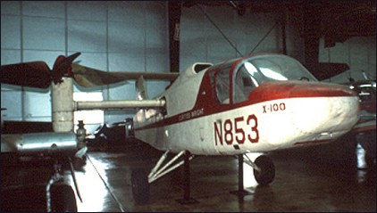
The Curtiss-Wright X-100 was a short-lived research program used to demonstrate the lift concept being developed for the Curtiss-Wright M-200 aircraft, which eventually became the X-19. The X-100 was to test the lift force concept and the gimbaled nacelles needed for a tilt prop configuration, and to test the glass fiber propellers needed to enable the use of radial lift. The X-100 was successful in that it verified the characteristics of the props, and produced data on noise, vibration, downwash, ground effect, stability, and control, and the piloting techniques needed to hover and transition a tilt prop VTOL. The airframe was all aluminum except for the aft half of the fuselage starting just aft of the cockpit, which was fabric covered. Design and fabrication was completed in just over a year, using concurrent design and construction. The design, fabrication, testing, and documentation of components occurred in a continuous and ongoing process. The X-100 was a high wing with T-tail and conventional landing gear. The fuselage was 8.6m long and consisted of welded tube construction. The shoulder mounted wing, with a span of 4.9m and an area of 2.1sq.m, had a wing loading of 560kg/sq.m. This was intentional so that the radial force produced by props could be demonstrated beyond any doubt. A three bladed, 3m diameter propeller was mounted on a gimbaled nacelle at each wing tip, and the two props rotated in opposite directions to balance yawing moments. Gross weight was 1580kg. The two-place cockpit had side by side seating. A rectangular engine intake was just behind the cockpit on the top of the fuselage. The T-tail, with an area of 2.1sq.m, was chosen to keep the stabilizer out of the props’ slipstream, giving the X-100 an overall height of 3.28m. To control pitch and yaw during hover, the engine exhaust was ducted out the rear of the fuselage and could be vectored up or down, and left or right by a device called a jetivator. This device was chosen for simplicity and to reduce weight. As a control effector, the jetivator could produce 63kg of pitch force and 18kg of yaw force. Roll control during hover was by differential control of the prop pitch. Altitude control was by means of the throttle. The X-100 originally had a rigid conventional landing gear. It eventually was replaced by tricycle gear to improve landing characteristics. The props were made of foamed plastic molded onto a metal shank and covered with a layer of urethane elastomer. Blades were wide and had a considerable amount of twist to maximize the amount of radial lift. The relatively low tip speed of 200m/s in hover minimized the amount of noise. The nacelles could rotate from pointing vertical to 12 degrees above horizontal. They rotated forward slowly at 2 degrees per second to allow the pilot to adjust power and attitude in order to prevent settling during the transition to cruise flight. They rotated back to vertical at 5 degrees per second. Curtiss-Wright’s program managers selected a Lycoming YT-53-L-1 turboshaft engine of either 650 or 825 horsepower. The U.S. Army, who had numerous YT-53-L-1 engines on hand, loaned two of them for the X-100 project. In exchange, Curtiss-Wright agreed to write a report on the engines’ performance. The fuselage had to be enlarged to accommodate the Lycoming engine. The design process started in February 1958. The first prop assembly was fabricated soon after and tested in NASA’s 12m x 24m wind tunnel starting in October 1958. It was run through the expected power operating range and at shaft angles from 0 to 90 degrees. These tests demonstrated that thrust in hover would be 10 percent below prediction (which was later confirmed in flight test), but there was enough excess thrust that the 10 percent loss was acceptable. Preliminary wind tunnel tests using models were performed at the Massachusetts Institute of Technology, then a powered model was run in the wind tunnel to determine stability and control characteristics. Tests using the actual aircraft eventually were run in NASA’s 12m x 24m wind tunnel. Reasonable correlation was achieved between wind tunnel tests and flight tests. Roll out of the completed X-100 was on December 22, 1958, at Curtiss-Wright’s Caldwell, NJ, facility, and the first engine run was performed on January 14, 1959. The first hover was made in a tether rig on April 20, 1959, to verify control power and feel. The first free hover test was performed on September 12, 1959, but extra weight was added to prevent the X-100 from getting out of ground effect. After three days of testing, hover flights of up to 20 minutes duration were made. The outflow velocities of air along the ground at various distances from the hovering X-100 proved to be similar to those of a helicopter of similar weight. Hover proved to be difficult as the pitch and yaw thrust provided by the jetivator was insufficient. Roll and yaw motions tended to couple together. The throttle was used to maintain height during hover, and lags in the engine response further compounded the problem. The X-100 also tended to weathervane into the wind during hover due to yaw moments produced by the wind hitting the props at an angle, which the jetivator’s yaw control could not counter adequately.
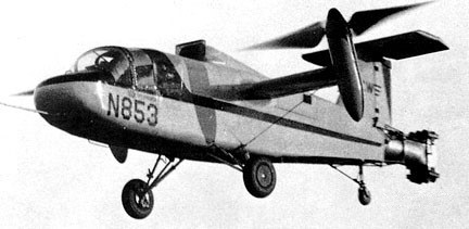
X-100 N853
Steady hovering was possible only up to about 4m, while the X-100 was in ground effect. If maximum power was applied on the ground, the X-100 would rise to about 7.6m, settle to within a few feet of the ground, then rise again and repeat several cycles of a slowly damped oscillation in height. The first transition from hover to forward flight was made on April 13, 1960. The transition itself was fairly simple. The pilot pressed a switch on top of the control stick to rotate the nacelles forward, then added power to prevent sinking. As the nacelles rotated, the X-100 picked up 30km/h of airspeed for each 10 degree of tilt. The conversion was done at 0.9 to 1.5m of altitude and very slowly to prevent settling to the ground. The nacelles were rotated down in 5 degree increments until a speed of 290km/h was achieved with the nacelle at a 15 degrees from horizontal. In general, low speed flight characteristics were unsatisfactory, especially in gusty air. The X-100 demonstrated a high pitch-up moment as forward speed increased, but directional stability, roll control, and longitudinal maneuvering were good in flight at 110km/h. At low altitude and up to 110km/h, the X-100 was notably free of mechanical vibration. Testing at altitude showed the aircraft to be buffet and stall free over a large range of angles of attack. STOL take-offs and landings were made with nacelle angle at 20 degrees from the vertical. Directional control was poor and was a problem during ground run. Smooth touch-downs also were difficult, much of the problem being caused by the landing gear being too stiff. There was considerable bouncing even at low touchdown speeds. The basic test program was completed on July 21, 1960. Test pilots from NASA visited Curtiss-Wright and flew the X-100 on August 12 and 13. This concluded test operations for the X-100 at the Caldwell, NJ, facility. With Curtiss-Wright satisfied that they had proven the radial lift concept, they turned the X-100 over to NASA. It was shipped to the Langley Research Center in October of 1960. It was used to study the effects of downwash on several types of ground surfaces, such as snow, grass, pavement, and packed dirt. NASA also studied problems associated with visibility in snow during hover and slow forward transition. This role was finished by October 1961.
The X-100 was test-flown until August 1965, when a gear case and prop failed. The pilots safely ejected and the ship crashed, but its technology was basis for X-200 and, ultimately, Bell-Boeing XV-22 Osprey.
Following the completion of tests at Langley, the X-100 was donated to the Smithsonian Institution. During its short career, the X-100 completed a total of 14 hours flying time and 220 hours of ground engine run time. It successfully proved the radial force concept, the feasibility of tilting nacelles, and low noise levels.