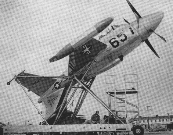
From 1949 the US Navy actively pursued a policy of VTOL research. The results were two prototypes, the Lockheed XFV-1 and the Convair XFY-1 Pogo. Both aircraft were of the ‘tail-sitter’ concept and powered by the 5500-shp (4101-kW) Allison T40-A-6 turboprop driving large contra-rotating propeller units. These provided more thrust than the weight of the aircraft, making possible VTOL operation.
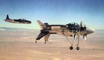
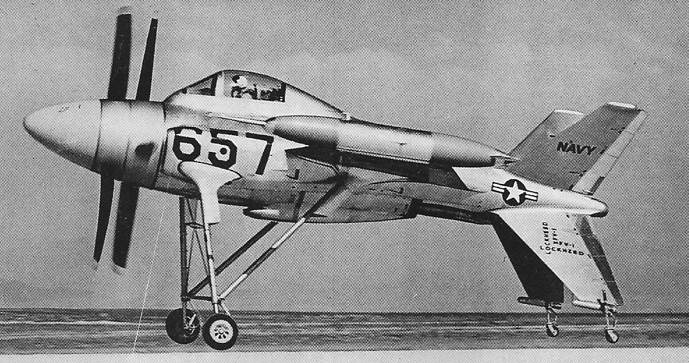
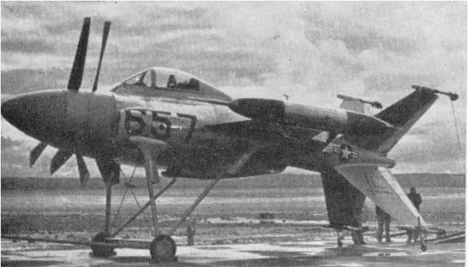
The XVF-1 was the more conventionally configured of the two types, with a mid-set wing of low aspect ratio, but for VTOL capability had a cruciform arrangement of tail surfaces indexed at 45 degrees to the wings. Each fitted with a small castoring wheel on the outboard end of its trailing edge. For flight trials with an engine not cleared for VTOL operation the type was fitted with a lightweight but very stalky fixed landing gear arrangement to permit conventional rolling take-off and landing, and in this guise first flew in June 1954. The aeroplane flew 22 times, in the process recording 32 operations in the vertical mode, when variation of the engine power made possible descending, hovering and ascending flight. No pure VTOL operations were undertaken with the only one of the two XFV-ls that flew.
The performance was similar to the P-80 Shooting Star.
The whole programme was cancelled in June 1955 and construction of the second prototype abandoned.
A contract for two prototypes of a new type VTOL aircraft was placed with the Lockheed company’s Georgia factory by the U.S. Army in June 1961. This followed more than two years of privately financed development of the jet ejector augmentation principle by Lockheed, including wind tunnel and test rig work.
The Army contract was for the Lockheed Model 330 Humming Bird, a research vehicle which was to be capable of development for use in the battlefield surveillance and Army support role.
Basis of the Lockheed concept is to augment the thrust of a jet engine by ducting its exhaust through a large diameter tube so that a large volume of cold air is drawn through it by friction and vacuum effect. This can augment the basic thrust of the engine by as much as 40 per cent.
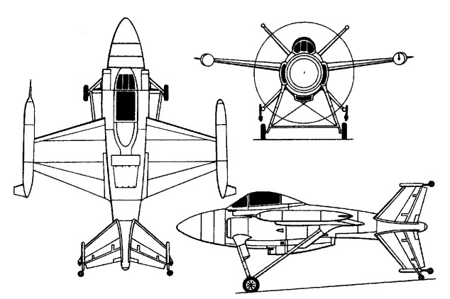
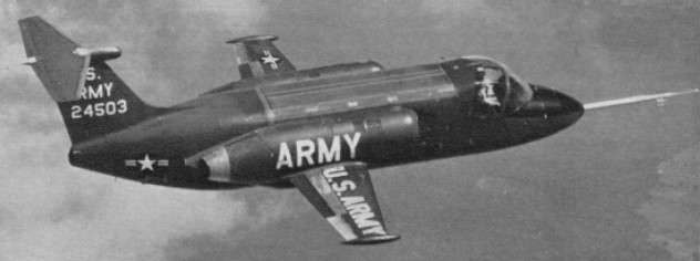
In the VZ 10 which was re designated XV4A in July 1962 two 3,000 lb.s.t. Pratt & Whitney JT12A 3s are located each side of the fuselage above the wing root. For vertical operations, their exhaust jet is turned through 180 degrees and ejected downwards through a series of nozzles into a duct or mixing area in the centre fuselage. Doors covering this duct, top and bottom, are opened. To convert from vertical to horizontal flight, the VZ 10 is first tilted slightly nose down to obtain a small thrust component from the jet exhaust from the fuselage duct. As speed builds up the wings begin to contribute lift and the thrust of one engine is then deflected from vertical to horizontal. This increases the speed still more and the second engine can then be deflected, too, and the duct doors are closed.
The first VZ 10 (62 4503) made its first flight at Marietta on July 7th, 1962, taking off conventionally. Hovering trials began in 1963. On 20 November 1963 the first successful flight involving transitions from vertical to horizontal flight, and vice versa, was completed.
The second VZ 10 was tested in the 40 ft by 80 ft low speed tunnel at Ames Research Center before joining the flight test programme.
By then, redesignated XV-4A, the two prototypes were handed over to the US Army. In late 1966 Lockheed modified one of the XV-4As to a new XV-4B configuration, the major change being replacement of the XV-4A’s two 1361kg thrust engines by four each of 1368kg thrust. Testing began in August 1968, but when the aircraft was destroyed in an accident in early 1969 further development was abandoned.
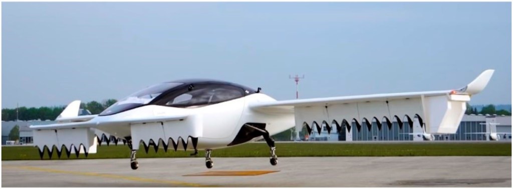
On 4 May 2019, Lilium flew its first flight of an untethered and unmanned five seat Lilium Jet at the Special Airport Oberpfaffenhofen in Munich, Germany. The full-scale prototype was powered by 36 electric ducted fans in configuration inspired by the Eagle prototype aircraft. After the first flight, which consisted primarily of hover, the Lilium Jet has expanded its flight envelope to include conversion to forward flight using the wing for lift, and several safety tests.
In April 2017, Lilium GmbH, a Germany-based start-up founded in 2015, flew the first flight of the Eagle prototype aircraft. This aircraft was unique in that it used 36 powered fans (12 in each wing and 6 in each forward canard) for lift and propulsion.
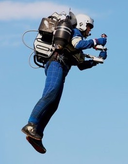
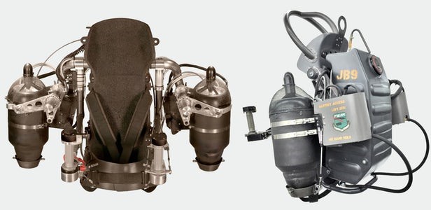
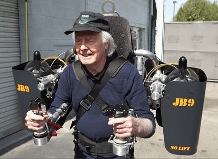
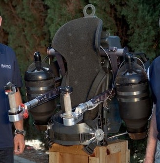
It’s a jet and a backpack; that can take off vertically. There’s a large suitcase that our whole JB-9 will fit into. It’ll fit in the back of a car. The JB-9 uses a carbon-fiber corset that straps to the pilot’s back, with the majority of the “backpack” section carrying fuel. The device can carry a total of 10 gallons of fuel, which it burns at around a gallon a minute. And the fuel itself is kerosene.
Mounted to each side is a small jet turbine engine that provides upward thrust. These engines mix ambient air with their exhaust gases to bring temperatures down to a comfortably warm airstream. The exhaust temperature actually declines really quickly.
On the left hand is a twistgrip controlling yaw. If I turn the hand to the left, it will spin to the left. There are some little yaw vanes at the bottom of each engine, a little cup that tilts backward and forward. They’re on push/pull cables. They’re always going in the opposite direction to each other, so if you vector the right engine forward, the left one goes backward and you get that yaw rotation.
On the right is a fly by wire throttle driving the engines. That actually works back to front compared to a motorcycle throttle. Going back into the 1960s, the way Bell had it set up, you turn your hand inwards to develop thrust. The JB-9 works the same way.
The twistgrips sit on the end of levers, which can be pushed up and down to tilt the jet engines, either individually or together. Rather than just vectoring the thrust, they vectoring the entire engine on a sort of gimbal arrangement, not only moving the line of the thrust, but moving the centre of thrust.
To go forward or backwards, which requires pitch, effectively its pushing both handles down, that’ll make it go forward. Pulling them up, or actually allowing them to come up, because that’s what they want to do under thrust, will make it go backwards. Or more likely, just slow down from speed. The whole thing is completely manual at the moment, it’s literally a pair of levers tilting the engines.
You don’t need much roll as it’s similar to that. Once you start a roll it will basically follow that. It’s kind of kinesthetic, once you start a roll by shifting your body one way and pushing your arms down a little to the left, it’ll continue that rolling motion to the left.
The JB-9 is limited to the required standards, which is 55 knots, or just over 100 kilometers per hour.
Vertical speed depends more on the fuel payload. There is an initial climb rate of 500-1000 feet a minute and as fuel burns off, you get extraordinary vertical rates. Being turbine engines, they don’t run out of performance as the air thins. They’ll just keep going, they’re compressing the air like a turbocharger.
The total endurance of the JB-9 is 10 minutes plus, depending on pilot weight. It also depends a little bit on temperature, altitude and that kind of thing, but that’s by no means as significant as the total pilot weight.
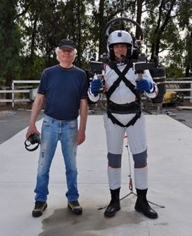
Jetpack Aviation is the project of Australian businessman David Mayman. He spent his life in software and mining and fairly sensible occupations, but his passion has been to build a jetpack. Nelson Tyler, an engineer and inventor based in Hollywood, and Mayman got together in 2005 and that’s what’s made it possible.
Tyler had worked on the Rocketbelt flight project at the 1984 Olympics, and for the last 45 years had been every bit as obsessed as Mayman with the idea of building a proper portable jetpack with decent endurance that anyone could fly. And the JB-9 jetpack they have demonstrated that meets most people’s expectations of what a real jetpack should be.
The creator of the “Hummingbird”, Rafi Yoeli of Isreal considered this machine to be a safe and truly simple-to-operate personal Vertical Take Off & Landing vehicle. It was inspired by an original 1950’s idea from the Hiller Company. The design was based on the use of a ducted fan, powered by four small internal combustion engines. The operator, standing on top, controled the vehicle by merely shifting his or her weight. A ballistically deployed emergency parachute unit was available as an optional extra.
Engines: 4 x Hirth F33-15A Width/Diameter: 2.2 m (7.2 ft) Height 1.9 m (4.2 ft) Empty Weight: 145 kg (320 lbs) Max. Gross Weight: 260 kg (572 lbs) Fuel Capacity: 19 liters (4.8 gal) Electric Start By Ground Assistance Max. Speed: 40 knots Max. Hover Height: 5000 feet Endurance: 30 minutes
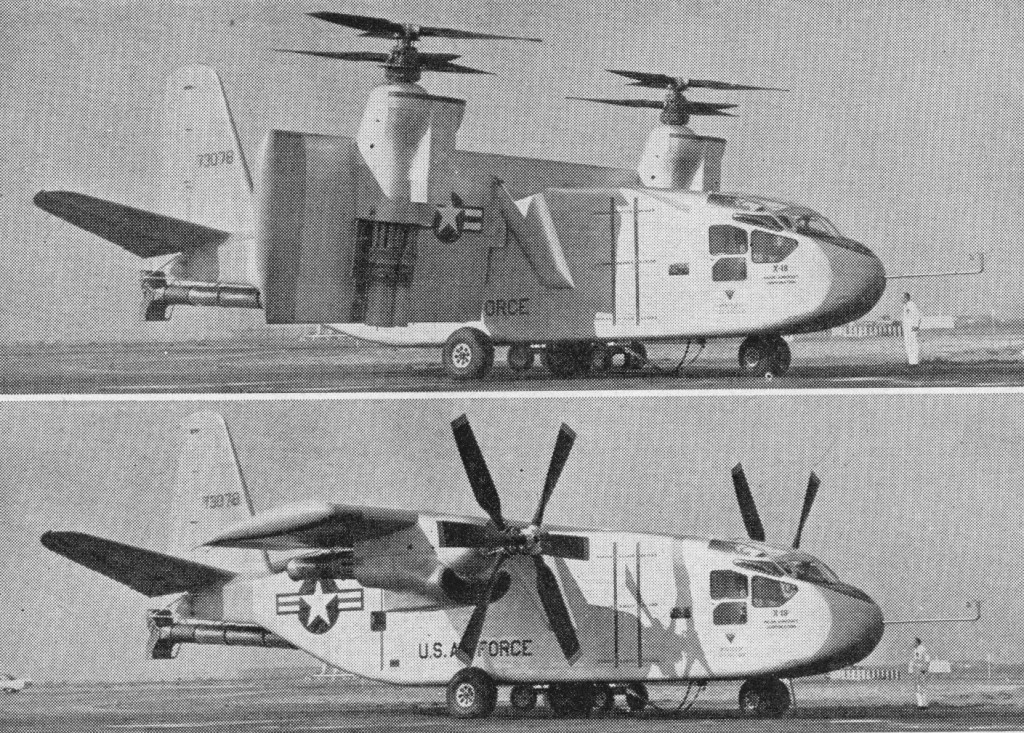
A prototype in the VTOL arena was the 33,000 lb Hiller X-18 tilt-wing convertiplane. The X-18 took to the air for the first time in November 1959, and in overall concept was configured as a transport type. Power was provided by two 5850-shp (4362-kW) Allison T40-A-14 turboshafts driving the two contra-rotating propeller/rotor units located one on each wing, and a 3400-lb (1542-kg) thrust J34 turbojet providing exhaust gases to a tail-mounted thrust diverter used for longitudinal control in vertical flight.
The first of the Army’s designated VTOL research aircraft was a continuation of the work to develop a ‘flying platform’. The idea for a machine of this kind, making use of kinesthetic control (in which the pilot leans in the direction he wishes to go) is attributed to Charles H. Zimmerman and dates back to 1940.
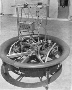
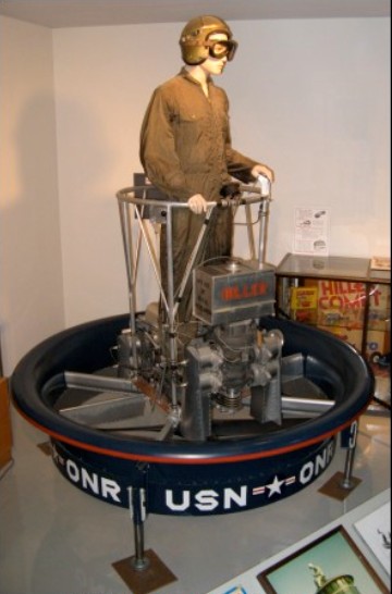
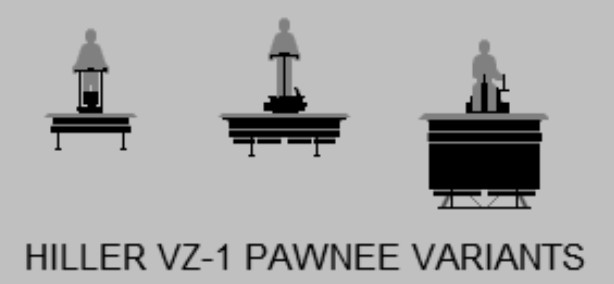
In the early 1950s, N.A.C.A. (the forerunner of N.A.S.A.) undertook a research programme at Langley Laboratory to prove the idea. Three types of aircraft were studied, each capable of carrying one man who stood on a platform, and supported, respectively, by a rotor, a ducted fan and compressed air. Subsequently, the Army placed contracts for further development of a rotor type flying platform by de Lackner (the Aerocycle) and of the ducted fan type by Hiller. The Hiller Helicopter Company had by this time already completed some studies in conjunction with Charles Zimmerman, in 1947, but no free flights were then achieved. A contract was placed with the company in 1953 for the construction of a prototype under Office of Naval Research supervision and this flying platform achieved its first successful untethered flight in February 1955.
The Pawnee featured a pair of contra-rotating rotors spinning inside a duct with a diameter of 1.5 meters (5 feet). Each rotor was driven by its own 30 kW (40 HP) two-stroke engine. The pilot stood above the duct, surrounded by a circular handrail and protected by a safety harness. He controlled the engines with a twist-grip throttle and leaned to guide the aircraft. The duct improved safety during takeoff and landing. The duct also provided additional lift, since there was a horizontal “lip” around its top edge that curved down into the duct. The airflow into the duct resulted in low air pressure above the lip, and the pressure difference between the top and bottom of the lip generated a net upward force, providing as much as 40% of the total lift of the aircraft.
In practice, speeds of up to 15 m.p.h. were achieved. Hand controls included the throttles to control vertical movement and a control to apply power deferentially to the two propellers in order to keep the platform headed in the right direction.
The Pawnee handled very well in flight tests. The machine was then modified with longer landing gear legs to increase ground clearance, and eight vanes were mounted underneath the duct to improve flight control.
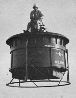
Results of the trials with their early platform were sufficiently promising for the Army to award Hiller a second contract, in 1956, for two larger examples of the flying platform. These were designated W‑ I E (serials 56‑6944 and 56‑6945).
VZ-1E
In the W 1E, the diameter of the duct was increased to 8 ft. and the chord was more than doubled. Three interconnected 30 kW (40 HP) Nelson H 56 engines supplied power to the counter rotating propellers. Controls were modified to be similar to those in a helicopter and the pilot had a rudimentary seat.
First flight of the W 1E (56 6944) was made on February 4th, 1955. It was delivered to the Army in 1959 but no further development occurred.