A four-seat VTOL aircraft of unusual configuration.
VTOL
Moller M400
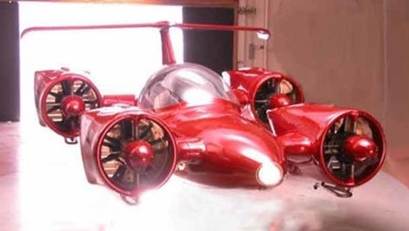
The Moller M400 Skycar is a flying car that promised to let you take off from your backyard and fly to your destination at 350 mph. Paul Moller won’t give up on his 50-year, $150 million quest to make his vision for a flying car a reality.
The M400 Skycar was developed over many years and first flown in 2001 at the company’s shareholder meeting. It has since flown (under a restricted environment) many times. This vehicle was featured on the covers of Popular Science, Popular Mechanics, and the topic of countless news articles and broadcasts including 60 Minutes, ABC, Bloomberg, CNN, and Discovery Channel.
In July 2017, Moller International listed the 2001 M400 prototype on eBay at the starting bid of $1 million. The more impatient bidder could have used the Buy It Now option for $5 million. The listing attracted no bidders. The M400 was relisted, this time with an opening bid of $250,000.
A collector who buys the M400 will receive it in its original 2001 flight form and condition, complete with eight Rotapower engines that produced over 720 hp allowing the M400 Skycar to take off and land vertically. It should be noted, however, in this original form, it does not have FAA approval and a condition of this offer is that it cannot be flown. Nonetheless, this vehicle can be the centerpiece of any car or aircraft collection in a public or private museum.
Moller 200X

The Moller 200X, the invention of Paul Moller, a former professor of aerodynamics and engineering, is built of graphite, carries computers, and eight lightweight Wankel engines. The proof of concept 200X is a flat, round 10 foot wide saucer, which can hover out of ground effect.
First flown in February 1989, the machine, which flew more than 150 times, is to make way for the production version, the Merlin.
Moller
Established 1983 to develop circular VTOL “power-lift” aircraft named Volantor M200X, which flew more than 150 times. Thereafter designed M200 and M400 Skycar two and four-seat VTOL lightplanes of very unusual configuration, with Mollar rotary engines and computer-reconfigured variable-lift vanes to provide thrust, and futuristic airframes with only small fixed lifting surfaces. Moller M400 prototype built in mid-1990s.
Millennium Jet SoloTrek Exo-Skelitor Flying Vehicle (SoloTrek XFV) / Trek Aerospace Springtail / Dragonfly
An American company named Millennium Jet of Sunnyvale, California, developed a recreational flying platform aircraft with the comic-book name of “SoloTrek Exo-Skelitor Flying Vehicle (SoloTrek XFV)” that got a certain amount of public fanfare for a time. It was an extremely unusual design that looked like an exotic piece of exercise equipment with twin ducted fans bolted on at the top. The fans tilted together to provide forward propulsion, or individually to spin the aircraft around. The pilot stood up in the frame and controlled the vehicle with two handgrips at the end of armrests. The right handgrip was a joystick for directional control and the left handgrip was the throttle. The pilot had flight instrumentation as well, provided by a display built into helmet goggles.
Two were built, with initial tethered flight of the first in 2002, but the machine never entered production. Millennium Jet evolved through whatever mechanisms to a new organization named Trek Aerospace that push a revised version of the machine named the “Springtail”, a derivative with a cockpit named the “Dragonfly”, and small UAVs based on the twin ducted fan configuration. The effort seems to have gone quiet.
Mikoyan-Gurevich MiG-23PD / MiG-23-01
One of two parallel studies to meet a VVS requirement for a new frontal fighter capable of operating from small, austerely-equipped forward bases, the MiG-23PD – Pod’yomnye dvigateli, or, literally, “lifting engines” – or 23-01 was first flown on 3 April 1967. Featuring a 57° delta wing planform fundamentally similar to that of the MiG-21 but scaled up 73.6%, the MiG-23PD alias 23-01 featured auxiliary lift engines close to the CG. Two 2350kg Kolesov RD-36-35 engines were accommodated by a bay inserted in the centre fuselage and provided with a rear-hinged and louvred dorsal trap-type intake box and a ventral grid of transverse louvres deflecting the jet thrust during accelerating transition. A similar arrangement had been tested by the OKB in the previous year with the MiG-21PD test bed, which, with a 90cm fuselage lengthening aft of the cockpit and two RD-36-35 lift engines, had entered flight test on 16 June 1966. The primary power plant of the MiG-23PD was a Khachaturov R-27-300 of 5200kg and 7800kg with afterburning, and air was bled from the last compressor stage for flap blowing, the combination of lift engines and blown flaps reducing take-off distance to 180- 200m. Armament consisted of one 23mm GSh-23 cannon and two AAMs – one radar-guided K-23R and one IR-homing K-23T. Flight test continued until the autumn of 1967 when further development was discontinued in favour of the parallel MiG-23-11.
Engine: 1 x Khachaturov R-27-300, 5200kg – 7800kg with afterburning
Max take-off weight: 18500 kg / 40786 lb
Wingspan: 7.72 m / 25 ft 4 in
Length: 16.80 m / 55 ft 1 in
Height: 5.15 m / 16 ft 11 in
Wing area: 40.00 sq.m / 430.56 sq ft
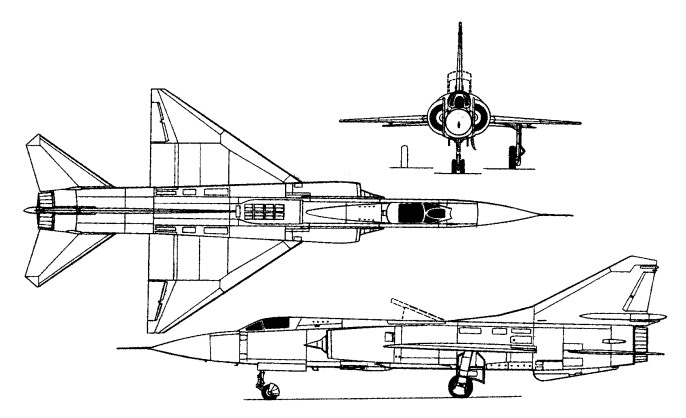
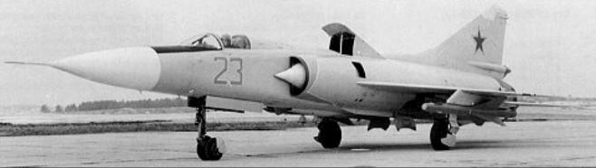
Mikoyan-Gurevich Ye-230 / Ye-231
Trials in the direct-lift approach started with the MiG-21DPD to validate the basic concept, but were then taken a stage further with the Ye-230 prototype. This was built in parallel with the Ye-231 variable-geometry prototype to ensure maximum commonality for any production type resulting from the twin programmes. The Ye-230 was of tailed delta configuration, was powered by a Lyulka AL-1F-1 afterburning turbojet, and had the same type of lift engine arrangement as the MiG-21DPD, namely two turbojets (probably Koliesov units) located vertically on the centre of gravity with air drawn from above past a rear-hinged louvred dorsal door and exhausted downward through a grid of ventral transverse louvres which could be angled by the pilot to provide a forward thrust component during transition to forward flight.
The Ye-231 variable-geometry prototype was almost identical to the Ye-230 apart from its lack of lift jets and the use of variable-geometry swept wings similar to those of the General Dynamics F-111, the first operational variable-geometry warplane. Comparative trials revealed the superiority of the variable-geometry arrangement. and the Ye-231 thus became the precursor of the MiG-23 fighter, later adapted with a modified nose and simpler engine arrangements as the MiG-27 attack aeroplane.
Matveyev Turbolet
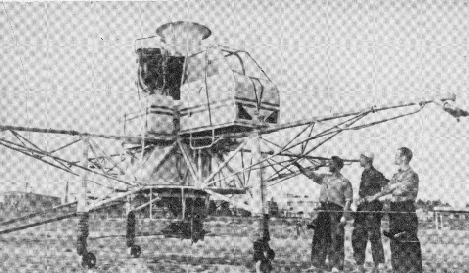
Demonstrated in Moscow during 1938, the Turbolet is a vertical take-off testbed developed by Prof. Vsevolod Matveyev. Comprising a turbojet engine mounted vertically, with fuel tanks and enclosed cockpit, the Turbolet is controlled by outrigger jet nozzles and vanes in the main jet stream.
Martin Aircraft JetPack
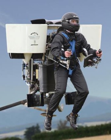
Oshkosh, Wisconsin, 2008, was the launch pad for a world first in personal flight today when Martin Aircraft Company unveiled the ultimate personal flying machine – the Martin Jetpack. Glenn Martin, Inventor of the Martin Jetpack and Managing Director of Martin Aircraft Company, showed the world that sustainable personal flight is now possible.
Glenn has devoted almost 30 years to the research and development of the Martin Jetpack. Glenn and a group of avionic, technical, design and production experts at Martin Aircraft Company have created a jetpack that flies 100 times longer than its predecessor the Bell Rocket Belt.
The Martin Jetpack has a patented fan jet technology, uses regular gasoline, complies with Ultralight regulations and is easy to fly after completion of a unique training program.
In 2005, Prototype 9 achieved sustained flight times, laying the foundation for a viable and successful pre-production prototype to be developed. In 2008 the Martin Jetpack was launched.
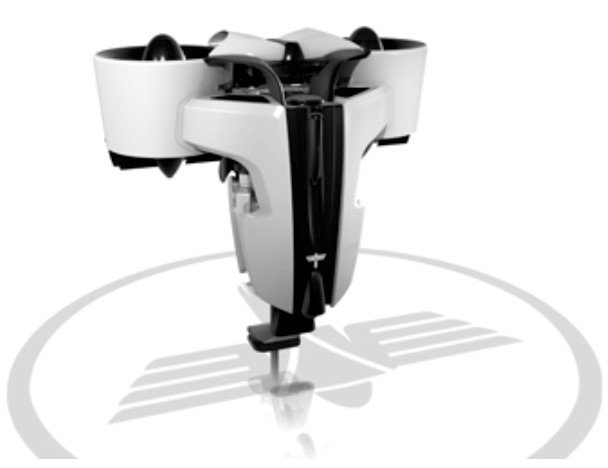
The core of this machine is the fan, its duct and the flow straighteners. These have cost the team countless hours as they pushed the boundaries of the science of ducted fans in a low speed environment. Mr Martin found that while many of the ‘facts’ older designs were based on were as solid as the day they were first committed to the text book, others were due either to the originators trying to simplify the calculations because of a lack of modem processing power, or had a fudge factor to cover steps in the process that didn’t become clear until high quality CFD systems were available.
A long series of experiments with Solidworks 3D CAD-drawn concepts run through CFD (a computer based simulation of a wind tunnel) brought about a series of promising steps forward in efficiency that were checked out on the workshop test rig. The team now have a fan blade that is not only light at roughly 100gm per blade, it also runs at 92 percent efficiency. The best Mr Martin can find elsewhere is the lift fans on the JSF which are published at 87 percent. The team have also worked hard to get the whole ducted fan package efficient across a broad speed range. The 2011 setup has a relatively flat efficiency curve with a small peak at around 60 km/h forward speed. Each fan unit is considered to be torque neutral which means the airflow from the duct is so close to straight that the twist is almost immeasurable, giving gains in thrust.
The fans needed a light, unobtrusive and reliable drive method which led the team to the modem synchronous belt. The latest designs have carbon fibre tensile cord inside the polyurethane belt with nylon facing on the teeth. The power transfer for width is better than for chain and challenges many gear-driven alternatives especially on weight. The major requirement for belts is to keep an alignment of better than half a degree and constant tension. Most belt drives use aluminium housings which shrink and grow with ambient temperatures let alone engine temperatures, so the decision was taken to go to a carbon fibre structure to all but eliminate temperature related dimension changes. The carbon structure also greatly assisted in keeping the alignment within spec.. The final touch was to make sure the drive and driven pulleys were fully supported by bearings on either side: no poor quality over hung shafts would be allowed in this design.
Once the horsepower requirements of the fans were known, a search of all known production engines was made. Power density, brake specific fuel consumption, package size and reliability were recorded, then checked against the requirements. No production engine had the power to weightt ratio needed allied with the high reliability the team demanded. Martin Aircraft sought advice from various companies and found that marine applications, such as outboards, shared many of the operational needs of the aviation world. Both users tend to run at three settings: idle; around 75% continuous; and 100% for extended periods. With this in mind, questions were asked of one specialist, Mercury Marine, to ascertain the level of stress an engine could be placed under and still achieve high reliability. The end result was four gentlemen For reliability and packaging reasons a water cooled V4 two-stroke was chosen. This gives a power pulse every 90 degrees which brings the peak and mean torque at the crankshaft nice and close together, resulting in a smooth output to the fans. To further smooth the power delivery, there is a ‘centre flex’ type rubber coupling before the drive enters the c!rive pulley. The cylinders are from Honda (CR 500 motor crosser), modified by replacing the steel sleeves with aluminium coated with nikasil. The change gives better heat transfer and reduces the engine weight by over 3kg. New heads have been made which have a carbon fibre top cover to keep the water in and the weight down.
The exhaust system is a simple yet brilliant piece of work which through its various interconnections and pipe lengths gives a lesser improvement at peak rpm compared to a full expansion chamber system, but functions well over a very wide band. The torque curve is one of the flattest I’ve seen, which means the horsepower line has no real humps or hollows as the rpm rise. Reliability is vital in a machine that has no wings (just a BRS ‘chute fitted) so the engine team have incorporated all the hallmarks of a reliable engine such as mean piston speeds below 15m/s, bore and stroke ratio kept below 1.15 / 1, and porting size and shape designed to protect the rings as they pass. All based on hard-won data from the marine industry where after tens of thousands of engines they have learnt a thing or two.
The cooling system has a neat (and patented) method of pumping air through the radiator. To understand it, think about blowing air across the top of a milk bottle. The airflow from your breath across the top creates a draw on the air in the milk bottle. The horizontally mounted radiator on thej etpack has ducts that sit on the side of the entry to the ducted fans so that the rush of air going into the fans pulls air through the radiator. The more horsepower applied the more airflow through the fans and therefore more flow through the cooling system. Another simple yet brilliant design.
The first prototype Jetpacks were manually controlled and apparently not hard to fly, but the team have their eye on a market where a high level of automation seems preferable. The fully fly-by-wire system uses the same unit as the Predator UAV for its air speed, gyro, magnometer, GPS and other critical inputs, but the processing and control is done by a dual redundant Martin Aircraft system. When creating it the team were helped immensely by a professor from Bremen University who joined for six months to apply his experience in control systems. He also helped with the creation of a proper flight simulator suitable for training and checking out software changes to the real thing. The fly-by-wire approach allows the operator to simply command the machine to rise or fall, turn left or right, leaving the control units to move the duct vanes and the cruciform, surfaces in the jetstrearn to create directional change while changing the engine output to control height and speed.
Release the controls at any time and the system will maintain height and gradually bring you back to stable hover.
Martin Aircraft has created a concept, not just a one-off machine. The current version suits US Part 103 rules, so it is limited in overall weight, speed and fuel capacity. Accepting these limitations opens up a large private market for the Jetpack. A slightly bigger ‘unregulated ‘ version on the same basic configuration can lift 200kg-plus payloads versus the current 115 kg and stay aloft for over 90 minutes. Still bigger versions exist on paper.
The 12th prototype featured a 200 hp V-4 engine driving two ducted fans. It had been flown to more than 3000 ft and 74 kph. The planned price at that stage was US$150,000 to US$250,000.
Standard Equipment:
Flight and Engine displays
Harness
Ballistic Parachute
Retractable undercarriage
Energy absorbing undercarriage.
Height: 5 ft
Width: 5.5 ft
Length: 5 ft
Structure: Carbon fibre composite
Empty weight: 250 lbs (excluding safety equipment)
Gross weight: 535 lbs
Useful (Pilot) Load: 280 lbs+
Maximum thrust: 600 lbs+
Fuel Capacity: 5 US gallons (as required by FAA Part 103,Ultralight Regulations)
Fuel burn: 10.0 gph
Engine: Martin Aircraft 2.0 L V4 2 stroke, rated at 200 hp (150 kw). Max 6000 rpm.
Electrical system: 12 V DC Battery, starter, 360 w alternator.
Rotor: Carbon / Kevlar composite diameter 1.7 ft
Max: 7058 rpm
Range: 31.5 miles (at max speed of 63 mph as required by FAA part 103).
Hover in ground effect: 8000 ft (estimated)
Hover above ground effect: 8000 ft (estimated)
Martin Aircraft Co
In 1998 the Martin Aircraft company was founded with the specific goal to research and develop a jetpack that could fly 100 times longer than the Bell Rocket Belt (26 seconds). In 2005, Prototype 9 achieved sustained flight times, laying the foundation for a viable and successful pre-production prototype to be developed.
The founder of Martin Aircraft Company and the inventor of the Martin Jetpack is Glenn Martin. Richard Lauder is the company’s Chief Executive.

Based in Christchurch, New Zealand, Martin Aircraft Company is developing the world’s first practical jetpack, the Martin Jetpack. Launched to global acclaim at the 2008 Experimental Aviation Association AirVenture air show in the USA, Martin Aircraft Company planned to fulfil its first customer orders in 2010.
