Developed with possible Army operational applications in view, the Ryan VZ 11 uses a totally different concept to obtain VTOL performance. The outcome of several years’ work on lift fans by General Electric Corporation, the VZ 11 derives its vertical lift from two ducted fans, one in each wing.
Unlike other ducted fans, above the General Electric version is powered by the jet exhaust from a turbojet engine which is directed on to turbine blades at the tips of the fan blades.
The VZ 11 layout has two 2,658 lb.s.t. General Electric J85 GE 5 turbojets in the fuselage, fed by a dorsal intake over the two seat cabin. For vertical operations, the fans are powered, together with a third fan in the nose which provides a small lift increment but is primarily for pitch control. For roll control, the thrust developed by the wing fans can be varied differentially by means of ‘butterfly’ doors over the inlets. Louvres under the outlets provide yaw control.
Once the VZ 11 is airborne, the louvres are moved to deflect the fan flow rearwards. This gives the aircraft a forward thrust component. As speed builds up the undercarriage is retracted. At about 120 knots, the wings provide sufficient lift to sustain flight and the exhaust flow from the two engines is then switched from the fans to direct propulsion nozzles. The butterfly doors and louvres close over the fan ducts and the aircraft continues as a conventional jet propelled type.
Two prototypes of the VZ 11 were ordered from Ryan in November 1961 as part of a U.S. Army research contract to investigate lift fans which was placed with General Electric. The designation was changed to VZ-5A in July 1962 and flight trials began in 1963. The XV-5 first flew in May 1964.
Republic Aviation joined GE and Ryan in XV-5A development and was directing flight tests at Edwards AFB in 1964. Republic would share in building additional prototypes if the craft met Army and DoD expectations.
XV-5A Engines: 2 x 1200kg General Electric J85-GE-5 Max take-off weight: 7690 kg / 16954 lb Empty weight: 5450 kg / 12015 lb Wingspan: 9.25 m / 30 ft 4 in Length: 13.75 m / 45 ft 1 in Height: 4.5 m / 15 ft 9 in Max. speed: 880 km/h / 547 mph Ceiling: 12200 m / 40050 ft Range: 1600 km / 994 miles
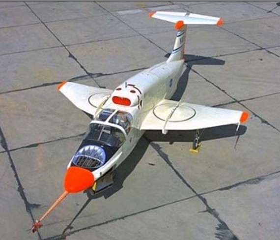
The X-13 was designed to explore the feasibility of building a pure-jet vertical takeoff and landing (VTOL) fighter aircraft. Secondary purposes included validating several Ryan designed VTOL control system concepts.
Ryan produced the X-13 Vertijet and XV-5 VTOL aircraft for the USAF. The X-13 was a ‘tail-sitter in the mould of the Convair XFY-1 and Lockheed XFV-1, though in this instance configured as a pure research type powered by a single 10,000-lb (4536-kg) Rolls-Royce Avon turbojet. The aeroplane first flew in conventional mode with temporary wheeled landing gear on 10 December 1955, and in ‘tail-sitter’ mode during May 1956.
The seat tilted forward 45 degrees to give the pilot a more comfortable position during vertical flight. Many early flights were made with no canopy. As first built, the X-13 had a huge fin, its height nearly as great as the wingspan. This was shortened during later testing.
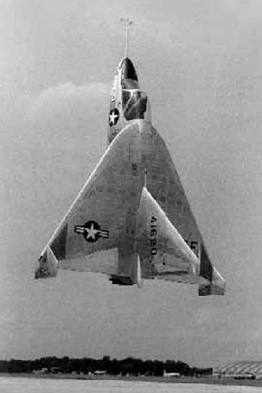
The success and efficiency of the X-13 flight test program provided a significant amount of data to the designers of subsequent VTOL aircraft designs. The X-13s proved that vertical flight, on jet thrust alone, was both technically feasible and practical. The ease with which the aircraft routinely transitioned from vertical to horizontal attitude, and back again, left little question as to the flexibility and operational utility of such flight modes.
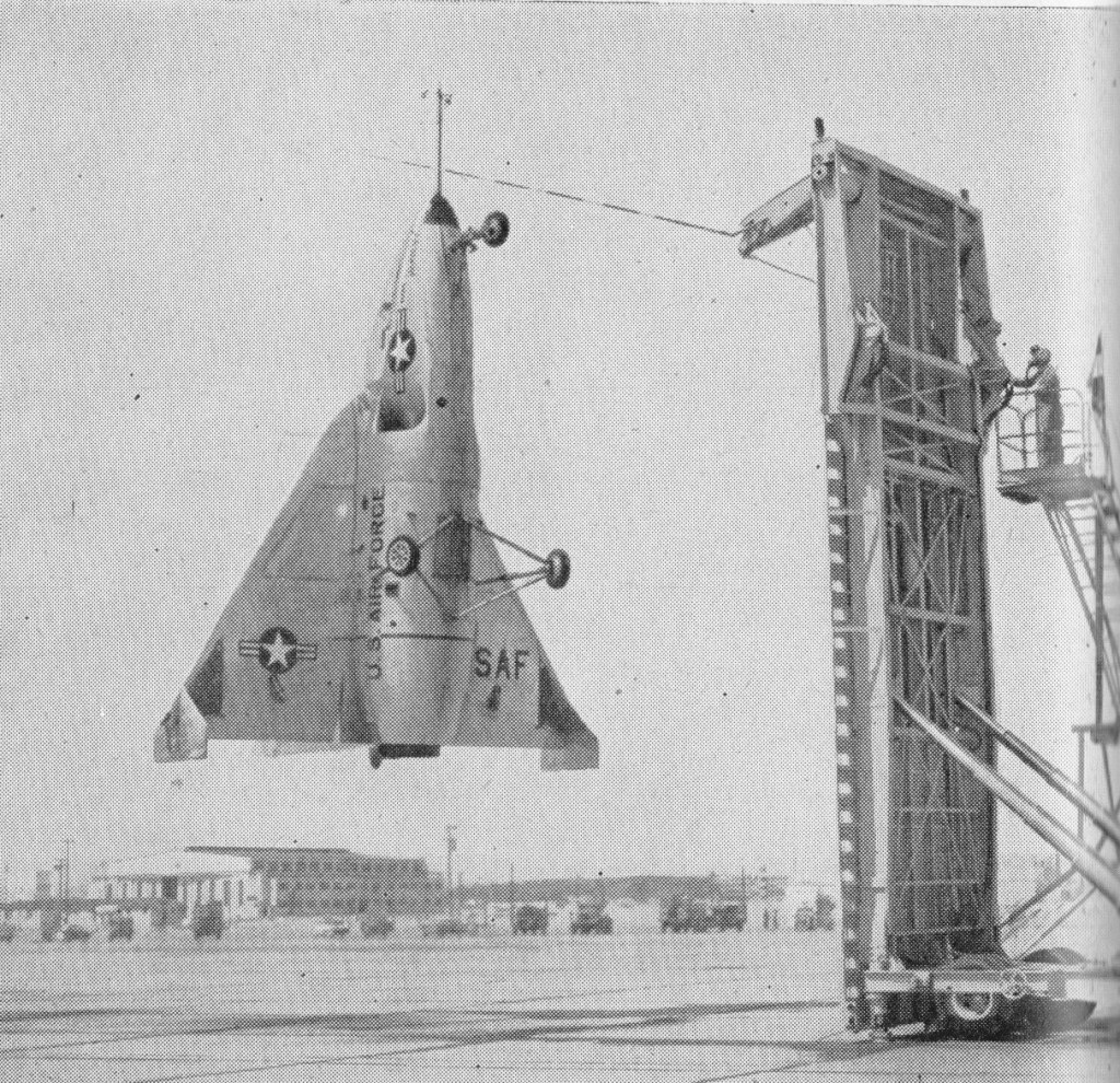
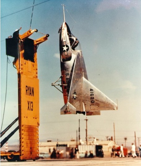
The delta-winged X-13 used a unique landing method, involving a special trailer, a hook and a striped pole. To land the pilot had to approach the trailer’s vertical base board without being able to see it. A pole marked with gradations protruded from the board and the pilot had to use this to judge his ‘altitude’ from the landing wire. In one demonstration at the Pentagon, the X-13 flew from its trailer, crossed the Potomac River, destroyed a rose garden with its thrust and landed in a net. Although this impressed the top brass, further funding was not forthcoming and the project petered out.
The last flight was made on 30 July 1957. Fastest Flight: 483 mph (approx) Highest Flight: 10,000 feet (approx)
Both X-13s survived their test program. The first aircraft is on loan from the National Air and Space Museum to the San Diego Aerospace Museum in California. The second aircraft is on display at the Air Force Museum in Dayton, Ohio.
Engine: 1 x 4540kg Rolls-Royce Avon RA.28-49 turbojet Max take-off weight: 3317 kg / 7313 lb Wingspan: 6.40 m / 21 ft 0 in Length: 7.13 m / 23 ft 5 in Height: 4.60 m / 15 ft 1 in Max. speed: 777 km/h / 483 mph
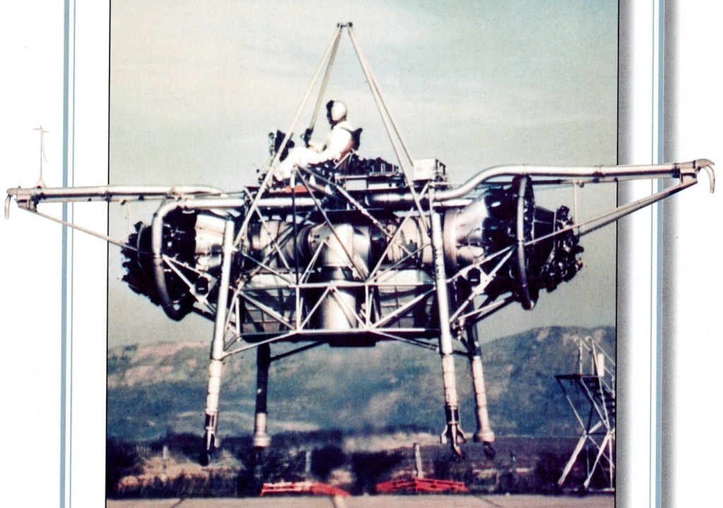
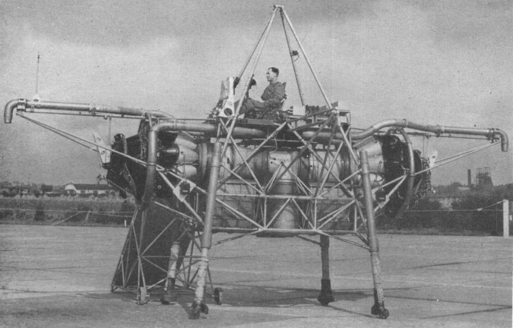
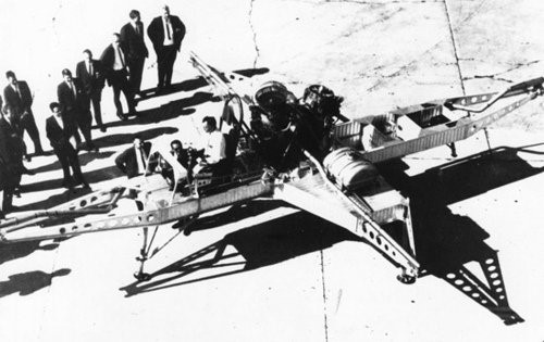
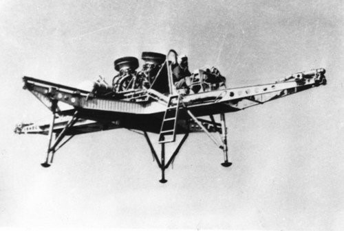
The Bedstead, officially called a Thrust Measuring Rig (TMR), was the brainchild of Doctor A.A.Griffith of Rolls Royce. It was a flat riser which hovered on the deflected exhaust gases of two Rolls Royce Nene jet engines. Compressed air nozzles provided directional control. The data gathered during the Bedsteads’ test programme in the mid 1950s led to the development of a special turbojet engine for jet lift, the RB108.
This was a radically new approach towards the development of vertical take off aircraft. Basically it consists of a tubular frame, said to measure about 20 ft. across, on which are mounted two Nene engines having a common, downward facing tail pipe. Space is also provided for fuel tankage and the pilot is seated in the normal attitude on the top.
The weight amounts to some 3.5 tons, and is a little less than the total maximum thrust from the 5,000 lb. thrust Nenes. The two engines are mounted horizontally, facing away from each other, the exhaust gases being turned through 90 degrees to enter a common downward directed tail pipe. The thrust so obtained provides for direct vertical jet lift of the rig.
Control in the pitch, roll and yaw planes is obtained by means of air jets bled from the Nene compressors. No aerodynamic control surfaces are used.
Capt. R.T. Shepherd, who was Rolls Royce’s chief test pilot until 1951, made the first fully free flight trials on August 3, 1954. During the previous 12 months or so, the ” jet lifter ” had undergone tethered flights, the amount of tethering being progressively relaxed as more experience was gained. The rig has since also been flown by Mr. H. Bailey, the company’s chief test pilot, and Sqn. Ldr. Harvey, of the R.A.E.
Flights have been made involving hovering and sideways and vertical movement. Landing is said to be very light and incurs no sudden drop. As with a helicopter, horizontal motion is produced by tilting the lift component, in this case from the propulsive jet, and a horizontal as well as a vertical thrust is obtained in this way.
Its pilot sat on a control station atop an entirely open-air framework of tubing, a calliope of ‘puff-pipes’ for attitude control arranged all around him. It was nicknamed the ‘Flying Bedstead’. NASA were interested in its reaction control system for their lunar lander simulator.
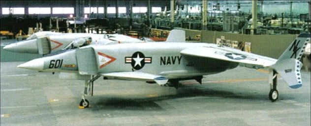
Rockwell became responsible in 1972 for development of the US Navy’s XFV-12A V/STOL Fighter/Attack Technology Prototype programme.
Basically a single-seat all-weather V/STOL fighter/ attack aircraft, the XFV-12A made use of an augmentor wing concept in which the efflux of its single Pratt & Whitney F401-PW-400 afterburning turbofan engine could be diverted to nozzles in the wings and foreplanes for V/STOL operations.
An ejector-flap system was incorporated in the design of each wing and foreplane, in which ambient air was mixed with turbine efflux in a ratio of 7:1 to provide the essential jet-lift for vertical operations and, when the flaps are raised or lowered progressively, for transition from vertical to horizontal flight and vice versa.
The main landing gear, canopy and other cockpit parts came from an A-4 Skyhawk. The main wing box and parts of the inlets were from an F-4 Phantom.
The XFV-12 did get off the ground – and was tested in a tethered mode, but the programme proved a disappointment and failed to provide an alternative to the Harrier.
Engine: 1 x 133.4kN Pratt & Whitney F401-PW-400 turbofan Max take-off weight: 11000 kg / 24251 lb Wingspan: 8.69 m / 29 ft 6 in Length: 13.35 m / 44 ft 10 in Height: 3.15 m / 10 ft 4 in
While the Army was pursuing the flying platforms, they were also investigating larger rotorcraft along similar lines, called the “flying jeeps”. Some sources imply that they were intended mostly for hovercraft operation, with an ability to fly over obstacles or impassable terrain when necessary, while other sources indicate they were regarded as helicopter-like utility vehicles that operated normally as flying machines. Whatever the case, the US Army Transportation Research Command began an investigation into the flying jeeps in 1956, leading to award of contracts for prototypes to Chrysler, Curtiss-Wright, and Piasecki in 1957.
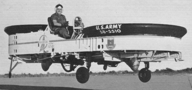
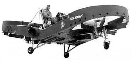
The first of the Piasecki flying jeep was the Piasecki “Model 59H AirGeep”, which was given the Army designation “VZ-8P”. The craft was built around two tandem 2.4 meter (8 foot) diameter, three-bladed, ducted rotors driven by two 135kW / 180 hp Lycoming piston engines. Both powerplants were connected to a single central gearbox so that both rotors would continue to turn even if one engine failed. The “Sky Car” had fairly conventional helicopter-type controls which provided directional stability through a series of hinged vanes mounted under each rotor duct. Forward motion was achieved by pitching the aircraft nose-down. The craft had fixed tricycle wheeled landing gear, and accommodated its single pilot and one passenger in seats sited between the two rotor ducts.
The AirGeep was 7.9 meters long and 2.7 meters wide (26 feet by 9 feet), with three-bladed rotors in ducts in the front and the back. The pilot and passenger sat between the ducts. The rotors spun in opposite directions to reduce torque effects.
The first of two Model 59 AirGeep (58 5510) examples ordered by the Army was first flown on 12 October 1958. Apparently it proved grossly underpowered, barely able to fly over a fence, and it was sent back to the shop, where the piston engines were replaced by a single 317 kW (425 HP) Turbomeca Artouste IIB turbine engine. The upgraded AirGeep flew on 28 June 1959. It weighed 1.1 tonnes (2,500 pounds) and could carry a payload of 550 kilograms (1,200 pounds), including the pilot.
Turned over to the Army shortly, the machine was subsequently given the designation VZ-8P (the “P” indicating Piasecki). Shortly after being accepted by the Army the VZ-8P was fitted with a single 315kW Turbomeca Artouste IIB turbine engine in place of its twin Lycoming pistons, and its first turbine-powered flight took place in June 1959.
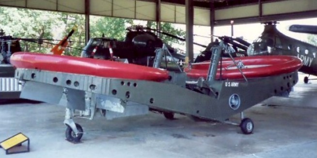
The AirGeep was put through trials for both the Army and the Navy over the next few years. The engine was upgraded again to a Garrett / Airesearch 331-6 engine, which had a higher power-to-weight ratio. For Navy trials, which began in June 1961, the rotorcraft was fitted with floats, and redesignated the “PA-59 SeaGeep”.
The second VZ-8P incorporated several significant design changes and was designated the Model 59H “Airgeep II” by Piasecki and the VZ-8P (B) by the Army. The Army Transportation Research Command issuing a contract for the “Model 59K”, which made its first non-tethered flight in the summer of 1962.
Piasecki PA-59K 58-5510
The AirGeep II was similar to the AirGeep, except that the aircraft was “bent” in the middle so that the rotors were tilted fore and aft, to improve forward flight characteristics. The AirGeep II used twin 298 kW (400 SHP) Turbomeca Artouste IIC turboshaft engines, once again linked so that if one failed the other would drive both rotors. One engine could also be coupled to the landing wheels to drive the machine on the ground.
Airgeep II 58-5511
The increased power allowed a maximum take-off weight of 2.2 tonnes (4,800 pounds). The pilot and observer had “zero-zero” ejection seats, allowing safe escape if the machine was on the ground and standing still, and there were seats for up to passengers.
Piasecki PA-59N 58-5510
During 1961 it was used for a series of trials by the U.S. Navy, operating from water and from the deck of a destroyer. For these, pontoons replaced the wheeled undercarriage and the VZ 8 became known as the PA-59N Seageep. Following completion of these trials, it was re engined with an AiResearch Model 331 6 turboshaft.
Piasecki VZ-8(P)
Neither version of the VZ-8P was dependent upon surface effect lift for flight and, though intended to operate within a few feet of the ground in order to make the best use of natural cover, both were quite capable of flying at altitudes of several thousand feet. Both versions were found to be stable and relatively capable craft.
The Airgeep was ultimately judged by the Army to be mechanically ill-suited to the rigors of field operations. The “flying jeep” concept was eventually abandoned in favor of the further development of conventional battlefield helicopters, and both VZ-8P examples were dropped from the Army’s inventory in the mid-1960s.
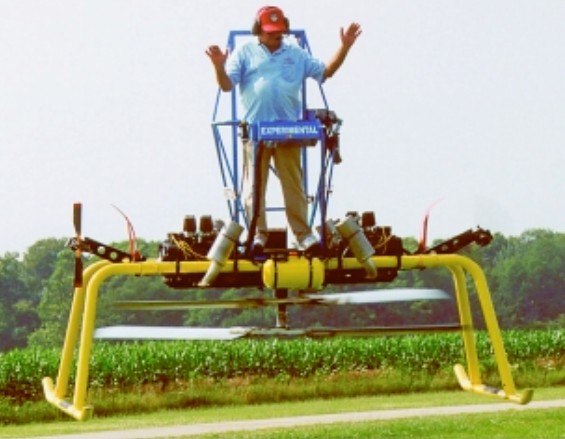
PAM 100B Single place, stand-on Individual Lifting Vehicle (ILV) with two composite 24″ diameter props for directional control. Simple tubular helicopter-type high strength airframe made of aircraft grade aluminum. Controls consist of a throttle and a fly-by-wire joy stick for directional control. There is no collective control. Kit price of $50,500 includes everything but shipping in 2009. Plans were also available.
Engines: (2) Hirth F-30 100 hp Rotor Blades: Four extruded aluminum Blade diameter: 9.17 ft Chord: 8″ chord
Min Speed Hover Cruise 45 mph Top Speed 60 mph Empty Weight 640 lbs Useful Load 360 lbs Gross Weight 1,000 lbs Skid Width 10 ft Height 9 ft Length 8 ft
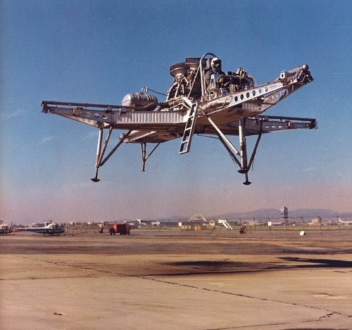
The North American FS-1 (Flight Simulator Number 1) Hoverbuggy was a 1965 open framework VTOL research vehicle with two 2200 lb GE YJ85 turbojets for lift, and four engine bleed-air nozzles on outriggers for control.
The craft had made 15 tethered and 185 free flights at altitudes up to 100ft when the program was shut down in 1967.
Engines: two x GE YJ85, 2200 lb Span: 23’0″ Length: 36’0″ Useful load: 1550 lb Max speed: 58 mph Range 10 mi
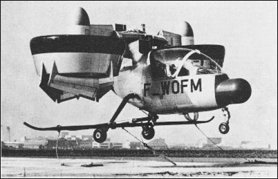
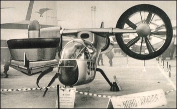
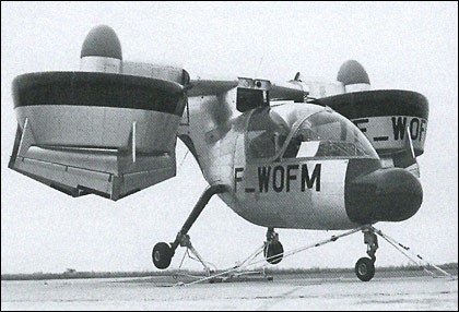
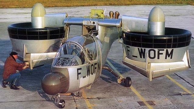
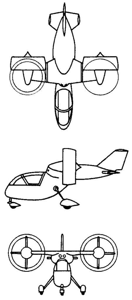
The Nord 500 was a single seat, company funded research aircraft. Its mission was to evaluate principles of the Tilt Duct propulsion concept for VTOL aircraft. The enclosed cabin contained an ejection seat. Two 317hp Allison T63-A-5A (or Allison T63-A5T, or 250-C18, depending on the source) turboshaft engines were located side by side in the rear part of the fuselage. They drove two 1.5m diameter props through interconnected shafts. Moveable vanes in the propeller slipstream controlled the duct positions aerodynamically. There were no other mechanical controls for rotating the ducts. The ducts tilted, along with a short section of wing. During hover, control in roll was by differential thrust, while control in pitch was by collective tilting of the ducts. There was no provision for attitude control of the fuselage because the ducts pivoted freely. The intended top speed was 218 miles per hour.
The first prototype was completed in Spring 1967 and was used for mechanical and ground tests. The second prototype made its first tethered flight during July 1968.
Nord merged with the Aerospatiale Corporation in about 1970, and the aircraft became known as the Aerospatiale N 500. Although a more sophisticated and more powerful version was in planning, all efforts on the Nord 500 appear to have stopped by 1971.
Nord-500 Engine: 2 x Allison T-63-A-5A turboshaft, 233kW Wingspan: 6.1m Length: 6.6m Height: 3.1m Max take-off weight: 1200kg Max speed: 350km/h