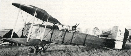
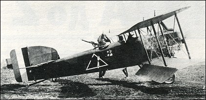
The Breguet 17 looked very similar to the Breguet 14. However, it had a larger tail fin and rudder, a shorter wingspan, a deeper under-camber and increased armament. The prototype of the Breguet 17 two-seat fighter flew in June 1918 but there were problems and the aircraft wasn’t available until after the Armistice. Production was planned for at least 1,000 series aircraft in 1919 but, after the Armistice, orders were cut back and only ten of the aircraft were built during the early 1920s.
The Bre.17, like the Bre.14, was an unequal-span two-bay biplane, powered by a 313kW Renault 12K engine and had much better performance. Ailerons were fitted to the upper wing only and were horn-balanced. The prototype was tested as a night-fighter, but no development in that role took place.
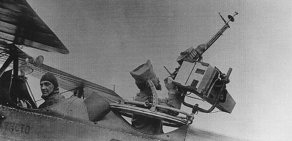
Production aircraft were powered by the Renault 12KI engine of slightly higher power, and had revised vertical tail surfaces. The rudder had rounded contours and was horn-balanced. Armament included twin Vickers machine-guns mounted on top of the engine cowling, synchronised to fire through the propeller disc, twin Lewis guns carried on a ring mount in the observer’s cockpit, and a third Lewis gun which could fire downwards and under the tail through a trap in the fuselage floor.
Bre.17s flew with a number of French escadrilles, but did not form the sole equipment of any single unit.
Engine: 1 x Renault 12KI, 336kW Take-Off Weight: 1840 kg / 4057 lb Wingspan: 14.28 m / 46 ft 10 in Length: 8.1 m / 26 ft 7 in Height: 3.42 m / 11 ft 3 in Wing Area: 43.3 sq.m / 466.08 sq ft Max. Speed: 218 km/h / 135 mph Ceiling: 7500 m / 24600 ft Armament: 5 x 7.7mm machine-guns
The Breguet 13, or AV 1, as it was known at the time, had a conventional look. The prototype took to the air on 21 November 1916 powered by a 220 hp Renault engine, with Louis Bleriot at the controls. After extensive trials by company test pilots, the aircraft was delivered to Aviation Militaire in January 1917 for their assessment. It immediately became apparent that the aircraft was far in advance of anything the British or the Germans had.
The STAe (Section Technical Aeronautique) had stipulated earlier in November that they wanted four types of aircraft, a three seat, long-range reconnaissance plane, a three-seat bomber, a two-seat army co-operation plane, and a two-seat fighter. Breguet submitted the aircraft stating variants of the aircraft could cover all the requirements.
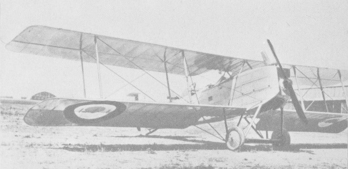
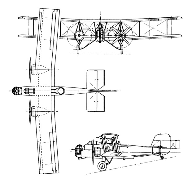
The Breguet 14 has two-bay wings, each with two aluminium spars, wooden leading-edge and ribs and fabric covering. The fuselage was of aluminium tube with fabric covering, except for metal top decking around the cockpits. Tail surfaces were fabric covered steel-tube structures. Conventional controls, with ailerons on the top wing only. Full span flaps on the lower wings dropped automatically at 70 mph to increase lift. Fuel was in two fuel tanks aft of the engine.
The 14B.2 bomber version was fitted with Michelin bomb racks.
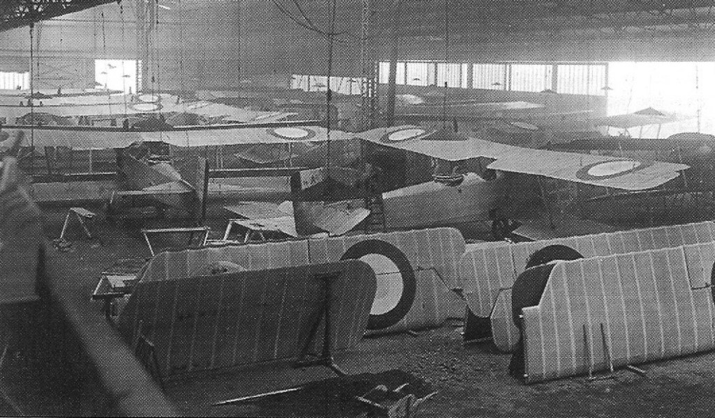
Breguet factory in 1918 assembling XIV A2
On 6 March 1917, impressed by the aircraft, the Aviation Militaire ordered 150 Breguet AV 1s (Breguet 13) to be used for reconnaissance. At the same time, the Michelin Company received an order for 150 Breguet AV 2s (Breguet 14), the bomber version. Because the aircraft were almost identical, it was decided to use the same designation for both – Breguet 14. In the months up until September 1917, orders totalling another 475 aircraft were placed.
Because demand was now outstripping supply, other companies were brought in to build the Breguet 14 under licence: Ballenger (3), Darracq (330), Farman (22), Sidam (300) and Paul Schmitt (275). The Paul Schmitt Company was already in the process of building a bomber, but the Breguet 14 had to take precedence, although they still managed to complete their own orders.
As far as the military was concern, the Breguet 14 was adaptable. It underwent numerous modifications, none of which affected its performance. On some of the aircraft, the wingspan and flap size was reduced. Different engines were tried, and various types of armament were installed and tested. Among these was one of the first air ambulances – the Breguet 14S (Sanitaire). The fuselage was modified to enable two stretchers to be carried inside.
Almost every escadrille was supplied with the Breguet 14, including the overseas units. During the short period of the war in which the USAS was involved, they purchased almost 400 of the aircraft. The first of their bombardment units, the 96th Aero Squadron carried out their first mission in June 1918 using Breguet 14 bombers.
Renault 300 hp and metal fuselage
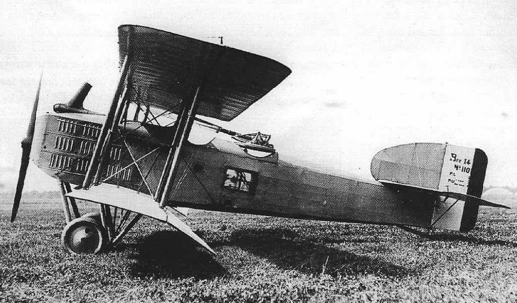
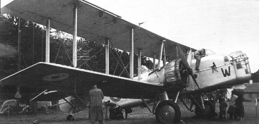
Powered by a Renault 12 Fcy water-cooled inline engine of 300hp / 238.5kW, the metal cowling was extensively louvred and a distinctive frontal radiator was fitted. The pilot was seated in the front and the gunner/observer behind. The Bre 14 A2 was armed with a single 7.7mm forward-fixed Lewis machine gun on the left side of the fuselage and an additional set of 7.7mm Lewis machine guns on a mounting in the rear cockpit. External stores could be carried when in the full bomber role.
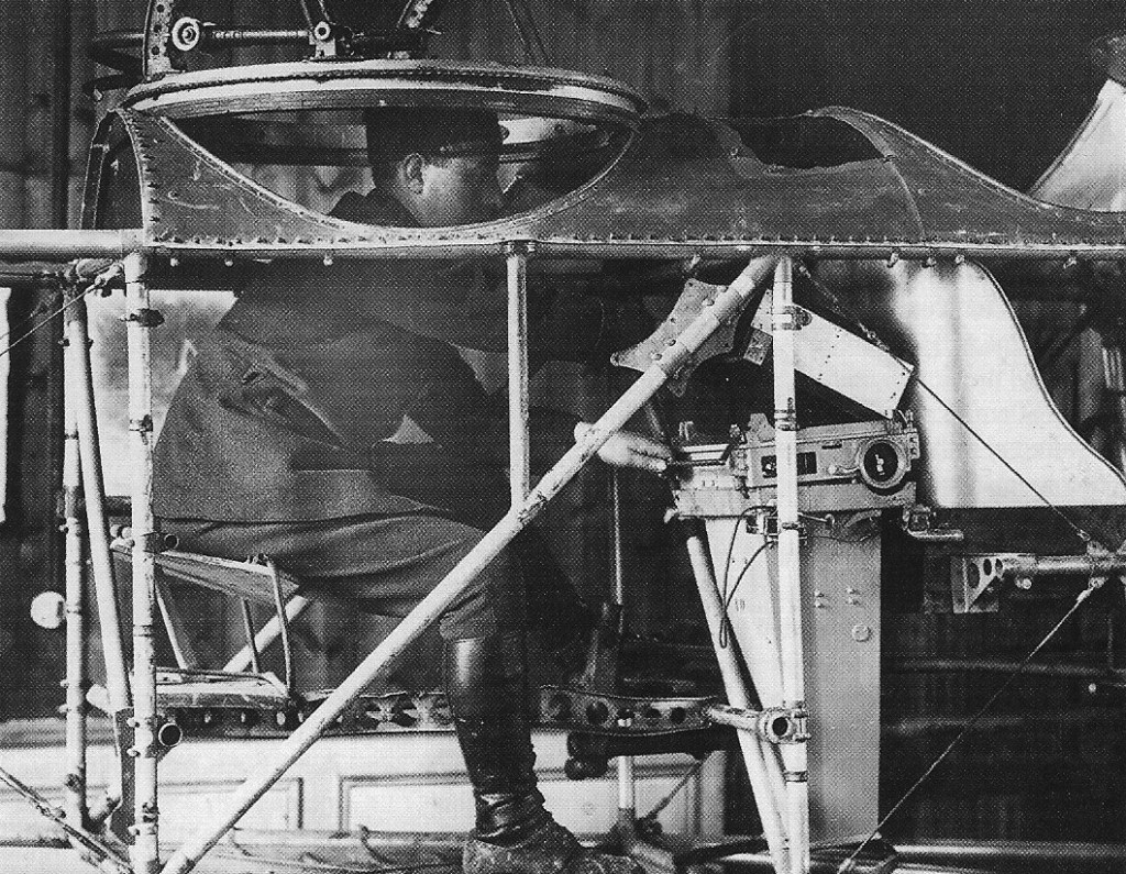
Breguet XIV Observer position and camera
The prototype flew for the first time on 21 November 1916.
Türk Hava Kuvvetleri assembled 16 Bréguet XIV A-2 in 1924 for the Turkish Air Force.
The reconnaissance version was followed into production by the bomber in the summer of 1917, the latter differing in having Breguet-designed automatic trailing-edge flaps on the lower wings and transparent panels in the sides of the observer’s cockpit. Late production examples of both versions had horn-balanced ailerons, the B2 aircraft thus equipped doing away with the trailing-edge flaps.
Breguet XIV A2 camera position
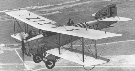
The B2 version could be fitted with an additional Lewis gun that fired downwards through the rear fuselage floor and had a maximum bomb load of 256kg, carried on underwing racks. A single-seat long-range version, known as the Bre 14 B1, was also built in limited numbers during 1918, and was intended to bomb Berlin. In fact it was little used and never mounted an attack on the German capital. Breguet 14 also equipped American and Belgian units during World War I, some powered by Italian Fiat A-12 and A-12bis engines. The Bre 14 A2 reconnaissance version and the Bre 14 B2 bomber equipped at least 71 French escadrilles on the Western Front by November 1918 and were also used by units in Serbia, Greece, Macedonia and Morocco. Many ex-French aircraft were handed over to Poland in 1919 and these took part in the fighting with Russia in 1920. The type formed part of the initial equipment of the Czech air arm, and others were operated in Brazil, China (70 with 298kW Lorraine-Dietrich engines), Denmark, Finland, Greece, Japan, Portugal and Spain. The Spanish equipped four squadrons in Morocco in 1922, using them on missions against Riff tribesmen. A further 40 were obtained in 1923. A small number of float variants were also built, mostly with a central main float and small wingtip stabilising floats. During 1919 Breguet 14 made a number of long-distance flights and Louis Breguet founded the Compagnie des Messageries Aeriennes with them, making regular air mail flights linking Paris with Brussels and London. These Bre 14 had special mail containers fitted under the wings. A cabin version with provision for two passengers was built as the Breguet 14T. Later came the improved Bre 14Tbis and the three-passenger Breguet 14T2. During the 1920s, the Lignes Aeriennes Latecoere company used more than 100 Breguet 14 in various versions on its routes between Toulouse and Dakar (West Africa) and between Natal and Santiago di Chile in South America. The Br 14S air ambulance, adapted from the Breguet 14T, was widely operated in the 1920s during the campaigns in Morocco and Syria. Each could carry two stretchers in the rear fuselage.
The Forges et Ateliers de Construction Latecoere began its interest in aviation in 1917 with an aircraft works at Toulouse-Montaudron. In 1917 P-G Latécoère turned from making munitions to licence-building aircraft for the Aviation Militaire Française. Total wartime production amounted to 800 licenced Breguet XIV and Salmson 2A.2 2-seat reconaissance bomber biplanes.
Initially, these licenced airframes do not seem to have received Latécoère designations. The licenced XIVs were refered to as Breguet-Latécoère 14s (or sometimes Latécoère Breguets). The designation Laté 1 may have been applied to licenced Brequets but there is some confusion with a 1918 2-seat fighter (of original Latécoère design?).
Latécoère converted large number of Breguet XIVs for civilian used in 1921-23 (190 for use by Aéropostale alone). None of these civil conversions seem to have received distinct Laté-x designations. Namings were as follows:
The ‘Torpedo’ name comes from the designation of Breguet’s own 14T and 14Tbis passenger conversions. Like the 14Ts, the Breguet-Latécoère 14 Torpedo was an aft cabin conversion as distinct from the cabin 14 ‘Salon’ conversions.
Breguet XIX TF Super Bidon Point d’Interrogation
Production was spread over seven manufacturers, in addition to the Louis Breguet factory at Velizy, near Paris, and 7800 of the type were built up to 1926, more than 2,500 appearing after the war ended in 1918.
The Breguet 14s were sold to 22 countries. There were fourteen variations that included using a number of engines and a large number of modifications. The type would continually see service in frontline French forces up until 1932.
Br.13 Engine: 1 x Gnome, 160 hp Wingspan: 49 ft 7 in / 15.3 m Length: 27 ft 10 in / 8.5 m Height: 10 ft 9 in / 3.3 m Empty weight: 2094 lb / 950 kg Loaded weight: 2876 lb / 1350 kg Max speed: 62 mph / 100 kph Armament: 1 x Hotchkiss mg Bombload: Flechettes
Breguet Bre.14A Engine: 1 x Renault 12Fcx, 220kW Wingspan: 14.4 m / 47 ft 3 in Length: 9.0 m / 29 ft 6 in Height: 3.3 m / 10 ft 10 in Wing area: 49.0 sq.m / 527.43 sq ft Take-off weight: 1740 kg / 3836 lb Empty weight: 1140 kg / 2513 lb Fuel capacity: 57.2 gal Max. speed: 180 km/h / 112 mph Ceiling: 6000 m / 19700 ft Range: 900 km / 559 miles Crew: 2 Armament: 3 machine-guns, 300kg of bombs
Breguet Bre.14B2 Engine: 1 x Renault 12 Fcy water-cooled inline, 300hp. Length: 29.10ft (8.87m) Wing span: 48.92ft (14.91m) Height: 10.83ft (3.30m) Empty Weight: 2,282lbs (1,035kg) Maximum Take-Off Weight: 3,483lbs (1,580kg) Fuel capacity: 57.2 gal Maximum Speed: 121mph (195kmh; 105kts) Maximum Range: 301miles (485km) Cruise: 75 mph. Service Ceiling: 13,993ft (4,265m; 2.7miles) Armament: 1 x 7.7mm Lewis machine gun in forward-fixed firing position. 2 x 7.7mm Lewis machine guns on mounting in rear cockpit. Up to 573lbs of external ordnance. Accommodation: 2 Hardpoints: 4
Breguet XIX Super Bidon Point d’Interrogation Engine: Hispano-Suiza 12 LB, 650 hp Wingspan: 18.30 m Length: 10.72 m Height: 4.08 m Wing area: 59.94 m² Max weight: 6375 kg Max speed: 250 km/h Ceiling: 6700 m Range: 9000 km
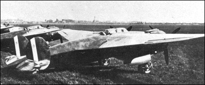
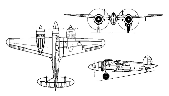
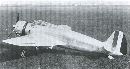
Initially, the prototype (MM.302) was flown with a single fin and rudder assembly, but poor stability necessitated the adoption of a rather cumbersome twin fin and rudder arrangement which marred the Ba 88s otherwise good aerodynamic form. The 1936 prototype was powered by two 900-h.p. Isotta-Fraschini K.14 radials and was one of the fastest aircraft in its class at the time of its appearance. A hybrid structure with stressed metal skin, shoulder-wing monoplane, the Lince had a structure of steel tube with a light metal outer skin.
Modified in 1937, the Breda Ba 88 Lince prototype, in December of that year, established several international records (with a load of 2,205 lb. flying 62 miles (100 km.) at 344.5 mph, and 621 miles (1,000 km.) at 326.3 mph).
Production orders for the Ba 88 were placed for the Regia Aeronautica and assembly lines were established by both Breda and 1.M.A.M. (Meridionali) with deliveries commencing late in 1938.
Regarded as an aeroplano di combattimento, suitable for attack, long-range reconnaissance or bombing operations, the Ba.88 then had its military equipment and weapons installed. Immediately, performance and flight characteristics fell off dramatically, but by then production orders were already in place. Bombs could be carried either in a bomb bay or semi-externally in recesses under the belly, and the Ba.88 could carry a 1000kg bomb load and four machine guns, three firing forward and a flexible gun in the rear cockpit. A window in the floor aided the pilot in aiming the bombs.
The production version featured considerable redesign and was powered by two 1,0000h.p. Piaggio P.XI R.C.40 radials which provided a maximum speed of 304 mph. Eight Ba.88 bicomando two-seat trainer version were built, with a raised instructor’s seat.
The first unit to receive the Ba 88 was the 7th Gruppo, which arrived in North Africa in September 1940.
On 16 June 1940, just after Italy’s declaration of war on France and her allies, the twelve Ba.88 aircraft from the Regia Aeronautica’s 19° Gruppo Autonomo made bombing and machine-gun attacks on the principal airfields of Corsica; three days later nine Ba.88s made a repeat attack. Analysis of these operations showed that the Ba,88 had only limited value, and any remaining doubts were settled when Ba.88s of the 7° Gruppo Autonomo joined action in Libya against the British. Fitted with sand filters, the engines overheated and failed to deliver their designed power. Attacks on targets at Sidi Barram had to be aborted in September 1940, the aircraft failing to gain sufficient altitude or maintain formation, and reaching a speed less than half that claimed by the manufacturers. The Ba 88 being taken out of production after only 105 aircraft had been built. Eighty-one by Breda and twenty-four by IMAM Meridionali.
In 1938 a Ba.88 bis was proposed with two Alfa Romeo 135 engines for the Caccia Combattimento competiton. It was not proceeded with.
By mid-November 1940 most surviving Ba.88s had been stripped of useful equipment and were scattered around operational airfields as decoys for attacking British aircraft.
In 1941 Agusta substituted two 840-h.p. Fiat A.74 R.C.38 radials for the Piaggios, increased wing span by 2.00m and fuselage length, and began the construction of a small series under the designation Ba 88M as ground-attack aircraft. Nose armament was increased to four 12.7mm machine-guns, and dive brakes were installed. Only three aircraft of this type were completed. These Breda Ba.88Ms were delivered to the 103° Gruppo Autonomo Tuffatori (independent dive-bombing group) at Lonate Pozzolo on 7 September 1943. They were flight-tested by Luftwaffe pilots, but that was the last heard of the Breda Ba.88.
A total of 149 were built.
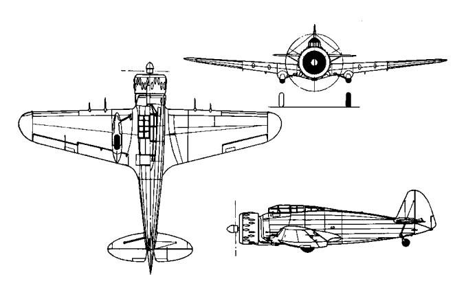
Breda Ba.88 Lince Engine: 2 x Piaggio P.XI RC 40, 986 hp Length: 35.4 ft / 10.79 m Height: 10.171 ft / 3.1 m Wingspan: 51.181 ft / 15.6 m Wing area: 358.872 sq.ft / 33.34 sq.m Max take off weight: 14883.8 lb / 6750.0 kg Weight empty: 10253.3 lb / 4650.0 kg Max. speed: 265 kts / 490 km/h Service ceiling: 26247 ft / 8000 m Wing load: 41.41 lb/sq.ft / 202.0 kg/sq.m Range: 871 nm / 1614 km Armament: 3x MG 12,7mm BredaSAFAT, 1x MG 7,7mm Breda SAFAT, 1000kg Bomb. int. / 3x200kg Bomb. ext.
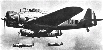
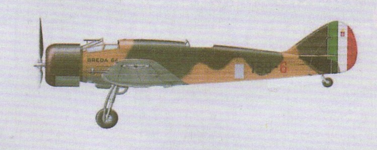
By the time the Ba.64 had entered service, work had already begun on a more powerful evolution of the system which delivered the prototype for the much improved Ba.65 fighter-bomber. The prototype first flew in September of 1935, went into series production that same year and were essentially copies of the prototype version. The Italian Isotta-Fraschini license-produced the French Gnome-Rhone K-14 engine of 700 horsepower and the early Ba.65 production forms all were fitted with the type.
Design of the Breda Ba.65 was the engine in a forward compartment along the airframe with an identifiable oversized cowling. The cockpit was situated directly behind the engine and fitted well forward of the aircraft’s center. Wings were of a low-set monoplane design and their bulk fitted ahead of amidships, each wing sporting well-rounded tips. The fuselage was stout in appearance and tapered off gently to become the empennage. The tail was topped with a single, rounded edge vertical tail fin and a pair of high-set horizontal planes, these also well-rounded at their tips. The undercarriage consisted of two main landing gear legs and a tail wheel. Each leg was affixed with a single wheel and the main legs recessed rearwards though only partly under each wing, the wheels half-exposed during flight. The tail wheel unit remained lowered at all times, even during flight.
Armament for the Ba.65 was all contained in the wings and was primarily a mix of machine gun systems. These consisted of 2 x 12.7mm Breda-SAFAT heavy machine guns joined by a pairing of 7.7mm Breda-SAFAT general purpose machine guns. For its intended ground attack role, the Ba.65 could be fitted with up to 1,102lbs of conventional drop ordnance. Categorized a ground attack aircraft, the Ba.65 was the only such Italian aircraft to serve in this role during World War 2.
A second series of 137 aircraft was built by Breda (80) and Caproni-Vizzola (57), before production ended in July 1939. They differed from the first production batch by having Fiat A.80 RC.41 18-cylinder, twin row, air-cooled engine was introduced from the 82nd production airframe onwards, driving a three-bladed propeller. The Fiat engine improved output to a relatively impressive 1,000 horsepower. Six Fiat-powered Ba.65s and four more of the Gnome-Rhone-powered version were sent to the Aviazione Legionaria in Spain in 1938. Experience in Spain indicated that the Ba.65 was suited only to the attack role, and the type served with most of the eight squadriglie attached to the two Regia Aeronautica assault stormi (wings), the 5° and 50°.
Production of the Ba.65 would last until 1939 to which all were officially retired from 1941 onwards, the aircraft now being wholly outclassed by newer and better breeds of aircraft and limited the Ba.65 to the ground attack role when possible.
A large number of the Ba.65s serving with Italian units were of two-seat configuration, with an observer/gunner in an open cockpit above the trailing edge of the wing. A smaller number of the type had a Breda L type turret, but in either case the observer/ gunner operated a single 7.7mm machine-gun. While offensive armament could theoretically comprise up to 1000kg of bombs, the load usually carried was up to 300kg in the fuselage bomb bay or, alternatively, up to 200kg on underwing racks.
Following Italy’s entry into World War II in June 1940, Ba.65s were involved in the fighting in North Africa against the British. They had a low serviceability rate in desert conditions and the last serviceable aircraft was lost during the British offensive in Cyrenaica in February 1941.
Of 218 Ba.65 aircraft completed and delivered for use, exports included 25 Fiat-powered Ba.65 two-seaters to Iraq in 1938, two of them dual-control trainers and the remainder with Breda L turrets; 20 Ba.65s with Piaggio P.XI C. 40 engines to Chile later in the same year, 17 of them single- seaters and three dual-control trainers; and 10 Fiat-powered two-seater Ba.65 bis with Breda L turrets to Portugal in November 1939 (Fiat A.80 RC.41). A single Fiat-powered production aircraft was tested with an American Pratt & Whitney R-1830 engine in June 1937 in anticipation of an order from the Chinese Nationalist government, but this failed to materialize. The Iraqi Ba.65s saw limited action against the British during the 1941 insurrection in that country.
Ten were exported to the Soviet Union in 1939. Aviazione Legionairia Ba.65s were a mix of K.14- and A.80-powered types. Spain: 1939, 11 surviving Ba.65s* (of 23) transferred to Ejercito del Aire. But at least some (eg #551) were ‘doppio comando’ dual-control trainers.
The Ba.65 designation was used to signify the definitive single-seat production version while Ba.65bis marked both a two-seat bomber variant and its similar two-seat trainer derivative.
Ba.65 K.14 Engine: Isotta-Fraschini K.14, 900 hp Armament: 2 x 7.7mm + 2 x 12.7mm Breda-SAFAT Seat: 1
Ba.65 A.80 Engine: 1 x Fiat A.80RC.41 radial, 1,000 horsepower. Wingspan: 39.70ft (12.10m) Length: 30.51ft (9.3m) Height: 10.50ft (3.20m) Maximum Speed: 267mph (430kmh; 232kts) Maximum Range: 342miles (550km) Service Ceiling: 20,669ft (6,300m; 3.9miles) Armament: 2 x 12.7mm Breda-SAFAT heavy machine guns in wings. 2 x 7.7mm Breda-SAFAT machine guns in wings. Up to 661lbs of internal ordnance in bomb bay and 441lbs of external ordnance held underwing. Accommodation: 1 Hardpoints: 2 Empty Weight: 5,291lbs (2,400kg) Maximum Take-Off Weight: 6,504lbs (2,950kg) RAI Ba.65 A.80s were re-engined with 14-cyl. Isotta-Fraschini K.14s
Ba.65 bis 2-seat version with open gun position, increased fuel capacity
Ba.65 bis L 2-seat version equipped with enclosed Breda L dorsal turret
Ba.65 Dive-bomber conversions of 40 Ba.65bis by Caproni Vizzola
The 1934 Breda Ba.64 ground attack aircraft saw only a few years of service beginning in 1937 before being replaced in 1939 by the improved Ba.65.
1st prototype MM 249 700 hp AR Pegasus 4-blade prop 2-seat fixed u/c
2nd prototype MM 250 700 hp Pegasus single-seat semi-retractable u/c
1° serie 1936 combine MM 249’s open gun position & MM 250’s u/c 42 built
Engine: 1 x Alfa Romeo 125 RC.35 radial, 650 hp Wingspan: 39.70ft (12.10m) Length: 31.89ft (9.72m) Height: 10.30ft (3.14m) Empty Weight: 4,475lbs (2,030kg) Maximum Take-Off Weight: 6,689lbs (3,034kg) Maximum Speed: 217mph (350kmh; 189kts) Maximum Range: 559miles (900km) Service Ceiling: 22,966ft (7,000m; 4.3miles) Armament: 4 x wing-mounted 7.7 mm Breda SAFAT mgs
Ba.64 dc: Doppio Comando pilot trainer conversion incl. 2nd prototype, MM.250 Armament: 2 x 12.7mm Breda-SAFAT heavy machine guns 3 x 7.7mm Breda-SAFAT general purpose machine guns. Up to 1,200lbs of munitions. Accommodation: 2 Hardpoints: 2
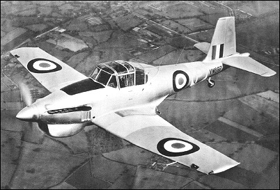
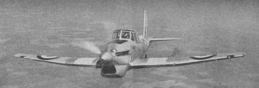
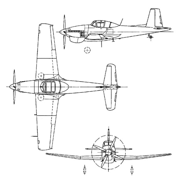
The P.108 Balliol was first flown on 30 May 1947, powered by a Bristol Mercury 25 radial. The Balliol was originally designed as an all-purpose advanced trainer to be fitted with turbo-prop engine to specification T.7/45.
With modification of RAF requirements, the Balliol was modified to take the Merlin 35 piston engine as the Balliol T.2, 187 being built.
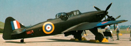
Balliol T.2 – Rolls Royce Merlin 35 – 1949
Three versions were produced: Balliol T.1 three-seater with a Mamba engine, first flown in prototype form on 24 March 1948 to become the first aeroplane in the world to fly solely on turboprop power
Balliol T.2 two-seater, produced for the RAF (162) with a 928kW Rolls-Royce Merlin 35 piston engine.
Sea Balliol T.21 WL732, RAF Cosford
Sea Balliol T.21 for the Royal Navy with deck-landing capability (30 built).
Balliol T.1 Engine: 1 x 1000shp Armstrong Siddeley Mamba Take-off weight: 3562 kg / 7853 lb Empty weight: 2724 kg / 6005 lb Wingspan: 11.99 m / 39 ft 4 in Length: 11.13 m / 36 ft 6 in Height: 3.23 m / 10 ft 7 in Wing area: 23.23 sq.m / 250.05 sq ft Max. speed: 494 km/h / 307 mph Ceiling: 11201 m / 36750 ft Seats: 3
Balliol T.2 Engine: 928kW, 1245 hp Rolls-Royce Merlin 35 Wingspan: 39 ft 4 in Wing area: 250 sq.ft Length: 35 ft 1.5 in Height: 12 ft 6 in Empty weight: 6730 lb Loaded weight: 8410 lb Max speed: 288 mph Cruise: 200 kt @ 10,000 ft. ROC: 1790 fpm Service ceiling: 32,500 ft TO dist 50ft: 1350 ft. Seats: 3 Armament: 1 x .303 Browning mg Bombload: 4 x 60 lb
Sea Balliol T.21 Engine: Rolls-Royce Merlin 35, 1245 hp Wingspan: 39.337 ft / 11.99 m Length: 35.138 ft / 10.710 m Max take off weight: 8412.1 lb / 3815.0 kg Max. speed: 250 kts / 463 km/h Range: 573 nm / 1062 km Seats: 3 Armament: 1x MG 7,7mm, 4x 27kg ext.
On the sale of its assets and business to a public company on 30 June 1934, Boulton & Paul became Boulton Paul Aircraft Ltd. Plans were also at hand to build a new factory at Wolverhampton. A contract was received for the construction of Hawker Demons fitted with a Frazer-Nash hydraulically-operated turret, which effectively protected the gunner from the slipstream enabling him to better train and fire his gun. The rear top fuselage consisted of a turtleback cowl attached to the gunner’s harness which folded up and down according to his movements.
Although development of powered turrets continued, it would appear that funding was somewhat limited, notwithstanding the enthusiastic response from the Air Ministry. The companys patents in this field ended in the Secret List, thus severely limiting further progress. John D. North, the company’s chief engineer, adopted a French design which met little official interest in France. Designed by J.B.A de Boysson, a hydraulically-operated turret was developed by the Societe d’Applications des Machines Motrices (SAMM) and Boulton Paul acquired full rights for its manufacture and development within the British Empire. Two turrets were ordered from SAMM for further trials, fitted with Browning machine guns in place of the four Darne 7 mm guns of the original design. Meanwhile, an original (Darne-armed) Boysson turret was tested in the nose of Overstrand K8175, and a single 20mm Hispano cannon installation was also tested in another turret on K8176.
During this time of radical change in fighter design and tactics, the Air Ministry was probably not completely confident that the emerging category of single-seat monoplane fighters, armed with a battery of eight guns buried in the wings, could make the grade. The issue of Specification E9/35 called for a two-seat day and night fighter, which should have its armament concentrated in a power-operated turret. In spite of the turret’s weight penalty, the aircraft was expected to perform within performance parameters close to those of contemporary single-seaters not only in speed but also in range of action.
Apart from Boulton Paul, F.9/35 brought proposals from Hawker, Bristol and Armstrong Whitworth; of these only the first two made it beyond the design stage, with one prototype each being ordered in the autumn of 1935. Boulton Paul commenced construction of their E9/35 prototype (K9310) in 1936 at their new Wolverhampton plant, although design had begun at Norwich. Close attention had been given to aerodynamic cleanliness in order to minimise drag. Of conventional construction, its fuselage was built in two main sections, the forward section built up of four longerons and a number of bulkheads, while the rear section was made up of three units, the two side panels and the top decking. The forward section housed the pilot’s cockpit over the wing centre section. The rear half of the fuselage incorporated the turret which was faired fore and aft with wooden-framed hydraulically-operated fairings which automatically hinged down to allow the guns to traverse.
The wings, built around two spars, were broken down into five parts: a centre section, two outer wing panels and detachable wing tips. The centre section housed the fully-retractable main undercarriage members and self-sealing fuel tanks, one 52 Imp. gallon (236 litre) tank on either side of the radiator bath. This tankage was later increased by another pair of 27 Imp. gallon (123 litre) tanks further outboard in the outer wing sections.
Its all-metal structure was conventional in most respects, its only unusual feature being the method of attaching the light alloy skinning to the stringers and ribs and then attaching these to the fuselage frames and wing spars. This obviated the need to pre-form the skins and, by riveting them while flat and countersinking the rivets, an exceptionally smooth finish was obtained.
The Boulton-Paul A. Mk.IID turret was a self-contained, removable unit, fitted with four .303 Browning machine guns with 600 rounds per gun. This unit weighed 3601b (162kg) empty, to which 881b (39.6kg) of armament and 1061b (48kg) of ammunition had to be added. Its hydraulically-operated system was completely independent from any other system in the aircraft.
The Boulton Paul Defiant was only the RAF’s third monoplane aircraft and the Defiant became the RAF’s first four machine gun fighter. On 11 August 1937, chief test pilot Cecil Feather took the turret-less prototype up for its first flight. The aircraft weighed 7,5001b (3,375kg) without its turret at this stage and was powered by a 1,030-hp (768-kW) Rolls Royce Merlin 1 engine with which it attained a maximum speed of 302mph (485.6km/h) , at which point it was named the Defiant. With the turret installed, vertical tail area had to be increased slightly; meanwhile a second prototype had been ordered (K8620).
When it had been decided to abandon further development of the Hotspur, an initial order for 87 production aircraft of what by that time had become known as the Defiant, was placed on 28 April 1937. Although drawings began reaching the workshops by the end of that same year, completion of the second prototype was delayed due to a change in power plant, from Merlin 1 to Merlin II. Apart from the increased tail area, it also featured redesigned exhaust stacks and cockpit canopy, and modifications to the undercarriage doors, thus bringing it very close to production standard. This set the first flight of K8620 back to 18 May 1939.
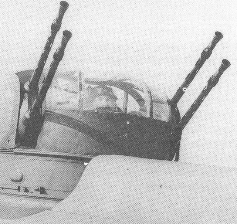
The second prototype was fitted with a Type A four-gun turret based on a French design already licensed for use on Boulton Paul’s Overstrand bomber, and this version with but minor changes became the production Defiant Mk1. The turret was electro-hydraulically operated with a mechanical backup and carried 4 x .303 Browning machine guns, electrically fired with cut-off points in the turret ring preventing activation when pointing at the propeller disc or tailplane. Whilst the gunner could lock the turret forward and transfer firing control to the pilot, this was rarely practised given forward elevation restrictions and the lack of pilot gunsight. The machine guns were paired two to a side and the entire turret system could scan a 360-degree area above the aircraft. Six-hundred rounds of 7.7mm ammunition were afforded each gun.
This was followed by another engine update with the selection of the Merlin III, the version with a standardised shaft for DH or Rotol constant-speed propellers, for production Defiants. The first production aircraft (L6950) performed its maiden flight on 30 July 1939, and by September it was with the A & AEE at Boscombe Down for official trials. These included dive-bombing trials at Orfordness, as L6950 had been fitted with underwing racks to carry light bombs. L6951 was transferred to the Central Flying School for handling trials. The Defiant was described as having excellent handling qualities, with very few vices. It found to be quite stable, with very little trim change being necessary when the undercarriage or flaps were extended or retracted. As with most aircraft of the time, it had a tendency to swing to port during take off, something which could easily be corrected. Comparative trials with No.111 Squadron Hurricanes were performed at Northolt on L6952 in October 1939, where the real situation emerged: the Defiant proved to be at a distinct disadvantage when compared with a single-seat fighter. The report clearly stated that than any average pilot flying a Hurricane could carve up an aircraft with the power/weight ratio of the Defiant.
Defiant F Mk.1
The first unit to receive the Defiant was No.264 Squadron, which had been formed at Sutton Bridge in October 1939 from where it moved to Martlesham. There it received its first two aircraft on 8 December 1939. By that time, more than half of the first production order had been completed; two further orders had been placed, one in February 1938 for 202 aircraft and another in May of the same year for 161. More orders were placed in December 1939 (150), February 1940 (50) and July 1940 (280).
264 Squadron was grounded on 28 January after a series of engine difficulties and hydraulic problems, the ban being lifted during the first week of February 1940. Although not fully worked up, two of the squadron’s flights were posted to Wittering on 21 March to fly convoy patrols. On 10 May, the entire squadron moved to Duxford, while two days later a Flight proceeded to Horsharn St Faith. That day, six Defiants from this Flight patrolled the Dutch coast and after strafing ground targets, escorted by Spitfires from No.66 Squadron, drew first blood by shooting down a Ju 88A. On 13 May, B Flight went into action, engaging a formation of Ju 87Bs of which they claimed four destroyed, when the Defiants were bounced by Bf 109Es escorting the ‘Stukas’; only L6974 escaped to tell the tale. Between 27 and 31 May Deflants were ordered to participate in providing top cover at Dunkirk, across the Channel. During this period, 264 Squadron claimed 65 kills, 37 of which were supposed to have been achieved on 29 May. There is no doubt that these claims were grossly exaggerated.
No.141 Squadron was the second Defiant unit to be formed, becoming operational at Grangemouth on 3 June 1940. On 19 July, 12 aircraft from the unit moved to Hawkinge, nine of which were scrambled at 12.30hrs. They had the misfortune of being bounced south of Folkstone by Bf 109Es which practically decimated the formation; L7014, although badly shot up, was to be the sole survivor. Pilots of No.111 Squadron claimed that the Defiants had shot down four of the aggressors during the fight.
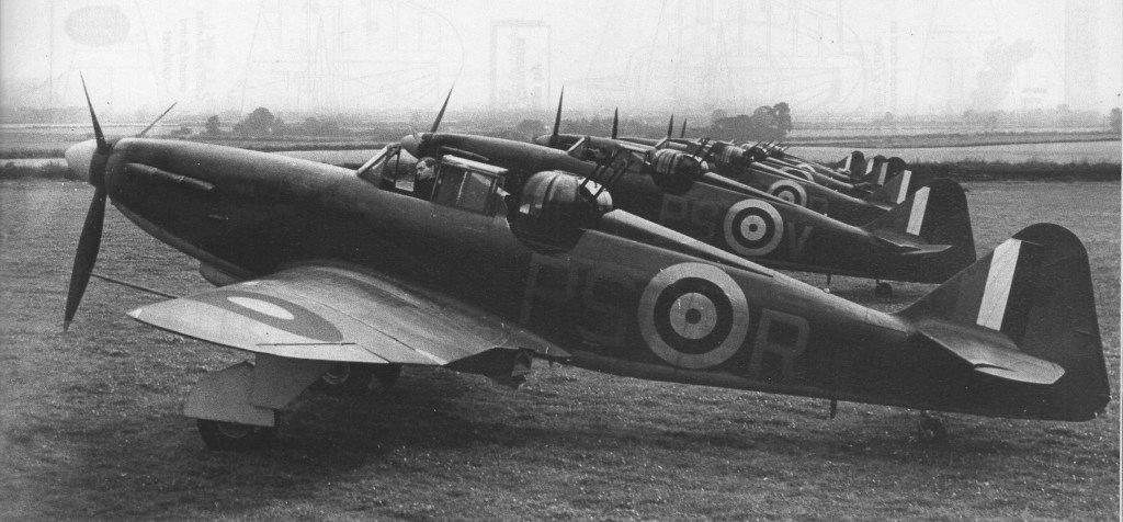
Defiants of No.264 Squadron RAF
During the height of the Battle of Britain, No.264 moved to Horchurch on 22 August; two days later the unit claimed three Ju 88s and a Bf 109E destroyed for the loss of two Defiants. On 26 August three Do 17s were shot down losing another Defiant in the process, while two days later four more of the turret fighters were lost.
Following the loss by 264 Squadron of 7 aircraft with 9 crewmen dead over the three days 26th to 28th August 1940, the Defiant was withdrawn from the day fighter role. On 28 August, 264 Squadron ceased operations and moved to Duxford the following day. Offensive patrols were cancelled and Defiant sorties were limited to anti-bomber patrols over the Channel from Matlesham Heath and Debden, until on 23 July the unit was retired to Kirton-on-Lindsey.
The Defiant Night Fighter No.141 Squadron pioneered night flying sorties with the Defiant on 1 July 1940, when L7997 flew a lone sortie. As the type had been withdrawn from daylight operations, both 141 and 264 Squadrons were operating practically as night fighter units by September. This coincided with the switch to night bombing by the Luftwaffe on London. B flight of No.141 Squadron moved to Biggin Hill, with A Flight taking up residence at Gatwick in October. Two He 111s were clairned by the unit as shot down on the night of 15/16 September. No 264 was similarly engaged, flying from Rochford, and later Debden. However, successes were few and far between and it was only with the arrival or airborne radar that the situation improved.
Defiants were now the Defiant NF.Mk I and were based on the standard Mk I marks. The NF.Mk IA followed soon afterwards with the AI.Mk IV / VI interception radar.
In the quest for better performance, Boulton Paul developed the Defiant F Mk II, more dedicated to the night-fighter role with the AI Mk IV airborne interception radar and powered by a 1,260hp Merlin XX. First flight of such an aircraft (N1550) was performed on 20 July 1940. Apart from the longer cowling to accommodate the new engine, both oil cooler and radiator were deepened and enlarged. The Mk II clocked a maximum speed of 315mph (506.5km/h) at 16,500ft (5,020m) during official trials. An order for 280 Mk Is placed in July was amended to cover the production of 63 Mk Is and 210 Mk IIs (a further seven Mk Is having been converted to Mk II standard on the production line).
Deliveries of the Mk II commenced in February 1941, by which time the Defiant had established itself in the night fighter role. By autumn of that year, AI Mk IV (and later Mk VI) radar was being fitted to Mk 1 Deflants (redesignated Mk IA) and Mk IIs (NF Mk II). Night fighter squadrons with the Defiant began to mushroom, these including No 96,125, 141, 151, 153, 264 and 410. By mid1942, the Defiant night fighter had been largely replaced by twin-engined types even in this role, No 153 and 256 Squadrons retaining their turret fighters up to the end of that year. A Flight of No 515 (Special Duties) Squadron kept its Defiants well into 1943.
As Defiants became surplus to needs of front line squadrons, they were transferred to Fighter Command air-sea-rescue units. Around 50 examples were fitted with an ‘M’ type dinghy stowage pack under each wing as ASR.Mk Is, serving with No 275, 276, 277, 278 and 281 Squadrons. After just six months of operations, these Defiants were withdrawn due to a number of problems.
The final production run covered 140 TT.Mk III target towing Defiants ordered in July 1941. A clear rearsliding canopy over the winch operator’s cockpit replaced the gun turret, a ‘B’ or ‘E’ type winch driven by a windmill was fitted to the starboard side of the fuselage while the target sleeves were housed in a faired pack fitted under the rear fuselage. First TT Mk 1 (DR863), based on the Merlin XX-powered Mk II, flew in January 1942. Apart from the order for new-build machines, the last 40 F Mk IIs on the production line were also completed as TT Mk Is, with the last (AA670) being delivered in May 1942. To these one has to add a further number of Mk IIs which, on being retired frorn squadron service, were converted for target-towing duties.
Quite a number of Deflants F Mk 1 were available for conversions to TT Mk III, a job assigned to Reid & Sigrist at Desford. N3488 became the development machine (rather than prototype) and apart from the Merlin III, distinguishable by its shorter nose, this version was similar to the TT Mk 1 in most other respects. About 150 Defiants were converted to Mk III standard between 1942 and 1943. Apart from most of the Gunnery Schools, where it replaced the Lysander, also the Royal Navy employed the Defiant target-tug overseas. For this purpose, in 1943 it became necessary to fit tropical filters to enable the Defiant to operate in hot and dusty climes.
At its peak of use, 13 RAF squadrons were Defiants equipped.
The Defiant also saw service with the Royal Navy and the air forces of Australia, Canada and Poland. A total of 1,064 machines were built.
Boulton Paul had embarked on a turret-less version way back in 1940, a single seat Defiant with a pair of .303in Brownings in each wing. The original prototype – K8310 – was modified to this standard; in fact one could say that it had reverted to the solid rear fuselage with which it had flown its initial flights. Notwithstanding that its performance would have been slightly better than that of the Hurricane, no official interest was shown in the single-seat Defiant.
At one time, a Merlin 24-powered version was under study, under the designation of TT Mk II; however the number of newbuild TT Mk Is and other conversions was considered as adequate for service needs, and the project did not proceed further.
Only one complete Boulton Paul Defiant example exists, this being held by the Royal Air Force Museum in Hendon, London.
Defiant Mk I Engine: one 1,030-hp (768-kW) Rolls-Royce Merlin III Wing span: 39 ft 4 in (11.99 m) Length: 35 ft 4 in (10.77 m) Height: 11 ft 4 in (3.45 m) Wing area: 250.0 sq ft (23.23 sq.m) Empty weight: 6,078 lb (2,757 kg) Maximum take-off: 8,600 lb (3,901 kg) Normal loaded weight: 8318 lb / 3773 kg Max speed: 259 mph / 302 kph at SL Maximum speed: 304 mph (489 km/h) at 17,000 ft (5,180 m) Cruising speed: 259 mph / 417 kph at 15,000 ft / 4572 m Initial climb rate: 1.900 ft (579 m) per minute Time to 15,750 ft / 4800 m: 8 min 30 sec Service ceiling: 30,350 ft (9,250 m) Range: 465 mi / 748 km at 259 mph / 417 kph Armament: four 0.303-in (7.7-mm) machine guns 600 rds each Crew: 2 Number built: 723
Defiant NF.Mk IA
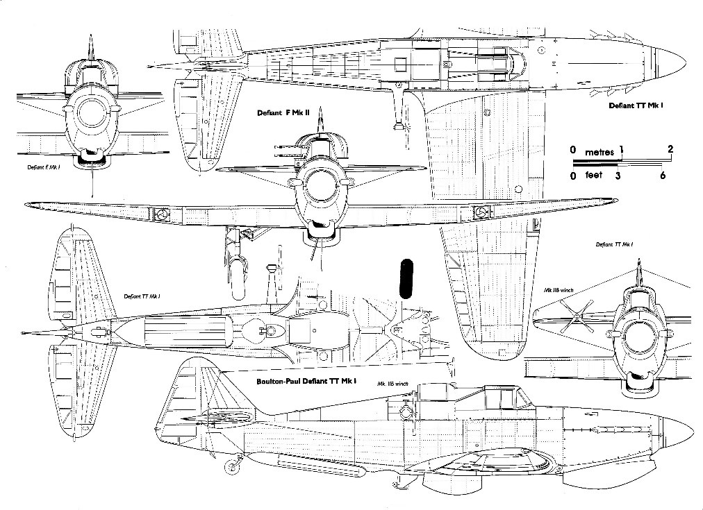
Defiant TT.Mk I
Defiant Mk II Engine: Rolls Royce Merlin XX, 1262 hp/954-kW Length: 35.335 ft / 10.77 m Height: 11.319 ft / 3.45 m Wingspan: 39.337 ft / 11.99 m Wing area: 250.048 sqft / 23.23 sq.m Max take off weight: 8425.3 lb / 3821.0 kg Weight empty: 6282.0 lb / 2849.0 kg Wing load: 33.62 lb/sq.ft / 164.00 kg/sq.m Max. speed: 272 kts / 504 km/h / 313mph Cruising speed: 226 kts / 418 km/h Service ceiling: 30348 ft / 9250 m Rate-of-Climb: 1,900ft/min (579m/min) Range: 404 nm / 748 km Crew: 2 Armament: 4x cal.303 MG (7,7mm) Number built: 210
Defiant NF.Mk II Engine: Rolls-Royce Merlin XX, 1,280 hp Top speed: 313 mph Service ceiling: 30,350 feet Range: 465-mile
After months of investigation from 13 August 1932, Boulton & Paul came up with a completely enclosed cylindrical turret with a hemispherical top, housing a single Lewis gun mounted with the barrel protruding through a narrow slot. Rotation of the turret was by means of compressed air, and the gunner could elevate his gun to around 70 degrees through a 360 degree horizontal field of fire.
The turret tested on an Overstrand was one of the two new prototypes completely redesigned by BPA, but built by SAMM with Browning guns. There was never a 4-gun Darne turret. The SAMM prototype of the Darne layout was a two gun test ring only.
By June 1933, a mock-up which incorporated also hydraulic balancing of the seat and gun had been officially inspected and accepted for installation in the Sidestrand. Having afforded such protection to the nose gunner, it was decided that the same treatment should be offered to the pilot by providing a fully enclosed cockpit. Furthermore, the aircraft was re-engined with Bristol Pegasus engines; due to all these improvements, what was supposed to be the Sidestrand Mk V was renamed ‘Overstrand’.
Three Sidestrand Mk IIIs were converted to Sidestrand Mk V configuration but were then renamed Overstrand. The first Sidestrand conversion Overstrand flew in 1933 with a 414-kW (555-hp) Pegasus 1M3 engine in a low-drag Townend ring cowling, an enclosed and heated cockpit, a shielded dorsal position, an autopilot and a fully enclosed nose turret.
The only production variant was the Overstrand Mk I, and 24 of this model were produced to replace the Sidestrands of No. 101 Squadron at Bicester from December 1934. Four Overstrands were also allocated to No. 144 Squadron.
The production Overstrand that entered service with No 101 Squadron from 1934 became the RAF’s first bomber with a power-operated enclosed gun-turret, which overcame the problems associated with firing movable machine-guns at high speed.
A total of 24 Overstrands were built, each powered by two 432kW Bristol Pegasus II M3 radial engines. These remained in service as bombers until 1937, then becoming gunnery trainers up to 1941. From 1937, the Overstrand was replaced by the Bristol Blenheim.
Overstrand Mk I Powerplant: 2 x Bristol Pegasus IIM3, 432kW (580 hp) Span: 21.95m (72ft). Wing area: 91.04 sq.m / 979.95 sq ft Length: 14.02m (46ft). Height: 4.72 m / 15 ft 6 in Max T/O weight: 5443 kg (12,000 lb) Empty weight: 3600 kg / 7937 lb Max speed: 153 mph at 6,500 ft Ceiling: 6860 m / 22500 ft Operational range: 545 miles. Armament: 3 x 7.7-mm (0.303-in) machine-guns plus 726 kg (1,600 lb) bombs Crew : 5
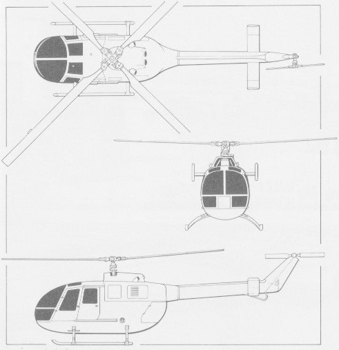
Design of the Bo.105 lightweight, general purpose helicopter was begun in July 1962 utilising basic experience gained by the company in the preceding few years in building the Bo.102 and Bo.103. The former was a non-flying, ultra-light helicopter trainer, and the Bo.103, flown for the first time on 9 September 1961, was essentially the same aircraft minus its fixed base. An enlarged version of the Bo.103 was proposed as the Bo.104, but this project was supplanted by the more promising Bo.105.
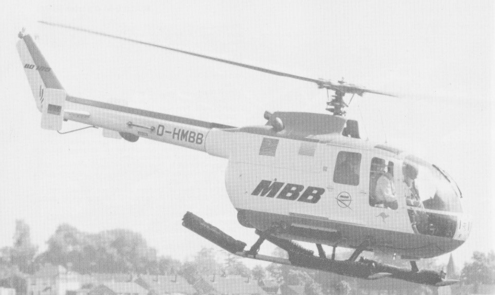
Under German government contract, ground rig testing of its radical rigid rotor and construction of the first prototypes began in 1964. The first prototype airframe (V-1) was ready for ground testing September 1969, powered by two Allison 250-C18 turboshaft engines and using the hinged-rotor from a Westland Scout, was destroyed on the ground at an early date by resonance problems. The second prototype, first flown on 16 February 1967 at Ottobrunn (Munich), was the first to take to the air with hingeless titanium rotor hub and composite rotor blades. Powered by twin Allison 250-C18 turboshaft engines, the non-articulated rotor, whose fold-able blades are reinforced with glassfibre, has been developed over several years by Bolkow in association with Sud-Aviation and has been adopted by the French company for its own SA.341 light helicopter.
Further changes and modifications led to the third prototype — the V-3 fitted with two German-built MAN-Turbo 6022 turbines (first flown on 20 December 1967), and to two pre-production models, the Bo.105 V-4 and V-5, the first of which made its maiden flight on 1 May 1969. Two Allison 250-C20 turbines were later installed on the V-4, which thus became the prototype of the definitive Bo.105C. Meanwhile, from spring 1970, new “droop snoot” design blades, which had a marked downward curvature on the leading edge, were introduced. These were made by MBB, the Messerschmitt-Bolkow-Blohm und Voss group — of which Bolkow and its affiliates had become part.
In 1972, the Bo.105 went into full-scale production at the company’s Donauwörth facility in Germany, and was offered with either Allison 250-C18 turbine engines or the more powerful C20. The helicopter was approved by the German Federal Authority LBA with the first power-plant in October 1970, after successfully completing autorotation trials in the autumn of 1969. Approval by the US Federal Aviation Administration followed in March 1971 and was extended to the C20 engines in August 1972, while the Canadian authorities certified the Bo.105 in April 1973. The German helicopter also received a British Certificate of Airworthiness in July 1973 and was recognized by the Italian Aeronautical Register in March 1974.
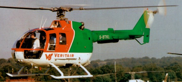
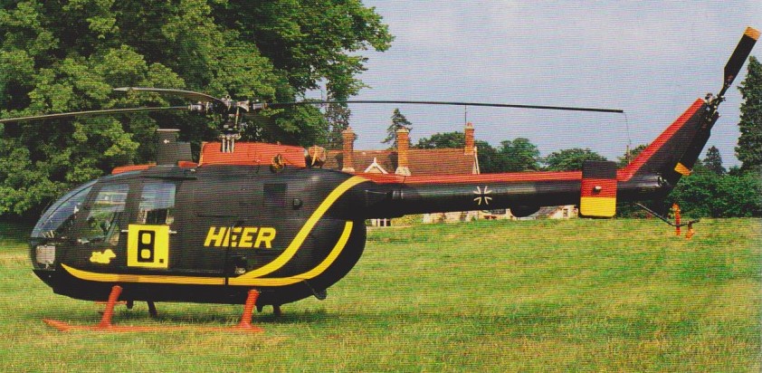
The German government ordered 20 for its “Katastrophenschutz” programme, to ensure rapid assistance in the event of a disaster. The military version differs little from the civil one. The antitank version can carry six HOT missiles, three on either side of the cabin, with a stabilized sight on the port side.
Bo 105 80+13, June 1986
The Federal German government authorised production of a total of 439 BO 105s for service with the German army. These comprised 227 of the BO 105 M(VBH), a liaison and light observation version of which deliveries began in 1980; and 212 of the BO 105 P(PAH-1) anti-tank version, each able to carry six Euromissile HOT missiles. Initial deliveries of this latter version, to Heeresfliegerregiment 16, began in December 1980. MBB has also developed an anti-tank version able to deploy eight Hughes TOW missiles.
Other military operators include the Mexican navy with six radar-equipped versions used for maritime patrol, and the Spanish army with 60 BO 105Ps, 57 of them assembled by CASA. The Spanish company is also assembling 80 105s for other customers, and there are active licence-assembly programmes underway in Indonesia as the Nurtanio NBO 105, and Chile. BO 105 LS helicopters produced at Eurocopter’s Fort Erie facility in Ontario, Canada.
MBB Bo.105C
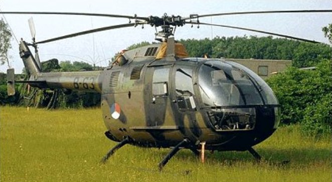
Others are in use in Brunei, Canada, Ciskei, Colombia, Holland, Iraq, Nigeria, Peru, Sierra Leone and Sweden. Sweden operates an unarmed SAR version known as the HR 9B. By 1991 more than 1,300 BO 105s had been delivered to 37 countries.
The civil version has also been a major export success and was initially marketed through Boeing in the United States before MBB set up its own US facilities. The BO 105C was superseded in 1975 by the BO 105 CB which became the standard production version.
By the end of 1981, total production of the Bo.105 exceeded 1100. More than 100 Bo.105s were in operation in the United States and these were joined in 1982 by the Bo.105CBS Twin Jet II variant, with 420shp Allison 250-C20B turbines, which, apart from having better flying capabilities, has 20 per cent more cabin room. The BO.105CB-3 variant of the standard production CB and CBS versions has a longer fuselage.
The Messerschmitt-Bolkow-Blohm GmbH Bölkow Bo.105 DBS-4 version has the 10-inch fuselage stretch at the rear of the cabin and the extra small rear side windows.
Further development of the Bo.105CBS led to the introduction in 1981 of the Bo.105LS (Lift Stretch) which combines the enlarged cabin with the uprated transmission of the military version and more powerful 550shp Allison 250-C28C engines to provide a much improved hot/high performance and external lift capability. Bo.105 LSA3 is a stretched cabin version. Featuring two Allison C28B engines, each with a separate drive to the main transmission, separate fuel and lubrication systems and dual hydraulic boost system. Providing the lift and directional control is a hingeless four-bladed main rotor and a semi-rigid two-blade tail rotor, all of fibre reinforced composite material.
The rear-loading clamshell cargo compartment is rigged to al-low accommodation of bulky cargos or stretchers by removing the rear bulkhead behind the passenger compartment.
Sales total more than 1300 to 37 countries by 1990. Navalised BO.105s are fitted with Sperry Primus 500 search radars and other maritime equipment, and have folding main rotor blades for shipboard stowage.
Messerschmitt-Bolkow-Blohm Bo.105HGH
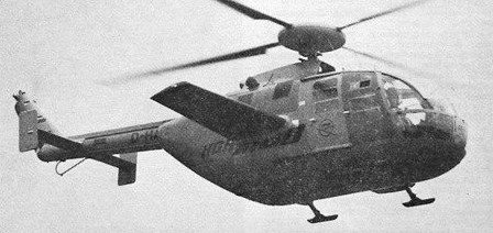
An BO 105 fitted with a rear fuselage fairing, rotor head fairing and four small individual landing gear skids, was developed under a high-speed research programme. Known as the BO 105HGH, this aircraft attained a speed of 372km/h in a shallow dive at max AUW in September 1973. Flight testing was continued in 1974 after the addition of 6.00m fixed wings with an NACA 230 section varying from 15% thickness/chord ratio at the roots to 12% at the tips. Airbrakes are mounted above and below the leading-edge of each wing, and a shorter-legged landing gear is fitted.
The HGH programme (Hochgeschwindigkeits Hubschrauber / High Speed Helicopter) ended on 4 March 1975 with a flight in which the aircraft attained a max speed of 404km/h; max blade tip speed was Mach 0.97. The BO 105HGH, which was converted from a pre-production BO 105 airframe, was to continue in use as a rotor blade testbed.
BO 105 CBS-4 description except where indicated:
DESIGN FEATURES: Four-blade main rotor, comprising rigid titanium head and GFRP blades, with titanium anti-erosion strip and pendulous vibration damper on each blade. NACA 23012 lifting aerofoil with drooped leading-edge and reflexed trailing-edge. Two-blade semi-rigid tail rotor. Tail rotor gearbox on fin. Main rotor 424 rpm. Tail rotor 2,220 rpm. Main transmission utilises two bevel gear input stages with freewheeling clutches and a spur collector gear stage. Planetary reduction gear; three auxiliary drives for accessories. Main transmission rated for twin-engine input of 257kW per engine, or a single-engine input of 283kW. Uprated transmission and Allison 250-C28 engines in BO 105 LS for exceptional hot-and-high performance. EC Super Five has new main rotor blades and performance improvements, including 150kg more rotor lift; better stability; and airframe vibration reduced to less than 0.1g.
FLYING CONTROLS: Main rotor has roller bearings for pitch change. Main rotor brake standard. Dual controls standard on EC Super Five.
STRUCTURE: Folding of two main rotor blades optional. Tail rotor blades of GFRP, with stainless steel anti-erosion strip. The fuselage is a conventional light-alloy semi-monocoque structure of pod and boom type. Glass fibre reinforced cowling over power plant. Titanium sheet engine deck. Horizontal stabiliser of conventional light-alloy construction with small endplate fins.
LANDING GEAR: Skid type, with cross-tubes designed for energy absorption by plastic deformation in the event of a heavy landing. Inflatable emergency floats can be attached to skids.
POWER PLANT: BO 105 CBS: Two 313kW Allison 250-C20B turboshafts, each with a maximum continuous rating of 298kW. Bladder fuel tanks under cabin floor, capacity 580 litres, of which 570 litres are usable. Fuelling point on port side of cabin. Auxiliary tanks in freight compartment available optionally. Oil capacity: engine 12 litres, gearbox 11.6 litres. EC Super Five additionally has scavenge oil filter and one-handed engine starting arrangement. BO 105 LS A-3: Two Allison 250-C2BC turboshafts, each rated at 410kW for 2.5 minutes, and with 5 minute T-O and maximum continuous power ratings of 373kW and 368kW respectively. Main transmission, type ZF-FS 112, rated for independent restricted input of 310kW per engine at T-O power or 294kW per engine for maximum continuous operation; or single-engine restricted input of 368kW at maximum continuous power, or 410kW for 2.5 minutes at T-O power. Fuel capacity as for CB/CBS. Oil capacity 4.5 litres per engine.
ACCOMMODATION: Pilot and co-pilot or passenger on individual longitudinally adjustable front seats with safety belts and automatic locking shoulder harnesses. Optional dual controls. Bench seat at rear for three or four persons, removable for cargo and stretcher carrying. A full EMS version is available. Both cabin and cargo compartment have panelling, sound insulation and floor covering. Entire rear fuselage aft of seats and under power plant available as freight and baggage space, with access through two clamshell doors at rear. Two standard stretchers can be accommodated side by side in ambulance role. One forward-opening hinged and jettisonable door and one sliding door on each side of cabin. Ram air and electrical ventilation system. Heating system optional.
SYSTEMS: Tandem fully redundant hydraulic system, pressure 103.5 bars, for powered main rotor controls. System flow rate 6.2 litres/min. Bootstrap/oil reservoir, pressurised at 1.7 bars. Electrical system powered by two 150A 28V DC starter/generators and a 24V 25Ah Ni/Cd battery; external power socket; stability augmentation system standard on BO 105 LS A-3, with hoist, firefighting kit, weapons fittings, mast-mounted sight and floats optional; EC Super Five has improved hydraulic system.
Variants:
BO 105C: Initial production version offered with either 236kW Allison 250-C18 or 298kW 250-C20 turboshaft engines.
BO 105 CB: Standard production version from 1975, with two Allison 250-C20B engines, operable in air temperatures ranging from -45 to +54°C. LBA certification received in November 1976.
BO 105 CBS-5: Military army/naval version for armed and non-armed missions; can be equipped with anti-tank missiles, rocket launchers. Gun pod or turret. First 12 ordered by the Republic of Korea Army; most assembled from kits by Daewoo. Include Boeing IR/optical sights and defensive aids suite.
BO 105 CBS: version with slightly lengthened fuselage to provide increased seating or cargo capacity
BO 105 CBS-4 / Twin Jet II: Version with increased rear seat leg room in a cabin extended by a 0.25m plug. Available in five-seat executive or six-seat high-density configurations. Identified by small additional window aft of rear door on each side. Marketed in the USA by MBB Helicopter Corporation under the name Twin Jet II. First CBS version certified in early 1983 by FAA for IFR operation in accordance with SFAR Pt 29-4, requiring two pilots, radar, Loran C and a separate battery, but not a stability augmentation system, although SAS was an option.
BO 105D: UK CAA-certified offshore version with modified equipment, supplied to customers in the UK and Nigeria
BO 105 LS: Canadian-built version of BO 105 CBS with increased power for ‘hot-and-high’ operation. Combining the larger cabin of the BO 105 CBS with two Allison 250-C28C turboshafts each with a maximum take-off rating of 373kW. First flight 23 October 1981, German LBA certification July 1984, followed by FAA and Canadian DOT type approval. In Spain, CASA assembled 57 of an initial 60 for the Spanish Army.
BO 105 LSA-3: Hot-and-high version, certified 7 July 1986 and first delivered February 1987. Uprated transmission and Allison 250-C28 turboshaft engines, rated at 410kW for 30 seconds. Built solely by Eurocopter Canada at its Fort Erie, Ontario plant.
BO 105 LSA-3 Super Lifter: Optimised for external load and heavylift missions; max T-O weight 2,850kg; upgraded tail rotor derived from BK 117C-1. Type certification granted October 1995. Built solely by Eurocopter Canada.
BO 105 LS B-1: One-off testbed C-FMCL, powered by two 307kW Pratt & Whitney Canada PW 205B turboshafts, made first flight 13 October 1988.
BO 105 M (VBH): Liaison and light observation helicopter for the Federal German Army, with strengthened transmission gearing, reinforced rotor components, a tail rotor with improved thrust and performance, a rupture-proof fuel system and a landing gear able to absorb higher energy levels. Production of 100 approved by the Federal government, to replace Alouette II. Deliveries completed in 1984.
BO 105 P (PAH-1): Anti-tank version of the BO 105 M, with same airframe improvements as BO 105 M, outriggers to carry six Euromissile HOT missiles, a stabilised sight above the co-pilot and a Singer AN/ASN-128 Doppler navigation system. The Federal German government gave its approval for the procurement of 212 PAH-1s for the Federal German Army. Deliveries began on 4 December 1980 and were completed in mid-1984.
EC Super Five: High-performance version of BO 105 CBS-4, derived from German Army PAH-1 upgrade programme; certified late 1993. New main rotor blades, improved performance and reduced vibration; dual flying controls as standard.
KWS-1 upgrade programme implemented in late 1980s, including installation of a digital weapon system, reduction in launcher weight, improved cooling unit, newly developed main rotor blades, and an increase in MTOW to 2,500kg.
BO 105C Engine: Allison 250 C20, 400 shp maximum, 385 shp continuous. TBO: 1,500 hrs. Rotor: four blade, semi rigid, glass fiber and reinforced plastic. Length: 38 ft. 11 in. Height: 9 ft. 7 in. Main rotor diameter: 32 ft. Disc loading: 6.22 lbs./sq.ft. Seats: 5. Empty weight: 2,698 lbs. Useful load: 2,372 lbs. Payload with full fuel: 1,339 lbs. Gross weight: 5,070 lbs. Power loading: 7.9 lb/hp. Fuel capacity (std.): 153 USG/1,033 lbs. Fuel capacity (opt,): 258 USG/1,742 lbs. Baggage capacity: 660 lbs. Baggage area: 57.5 cu. ft. Maximum sling load: 1,984 lbs. Rate of climb: 1,250 fpm. Service ceiling: 17,000 ft. Single engine service ceiling: 4,200 ft. Maximum speed: 167 mph/145 knots. Cruise: 140 mph/122 knots. Econ cruise: 124 mph/108 knots. Range @ max cruise (45 min res., std. tanks): 385sm/335nm. Range @ econ cruise (45 min res., std. tanks): 350sm/304nm. Duration @ max cruise (no res., std. tanks): 3.5 hrs. HIGE: 7,900 ft. HOGE: 5,850 ft. Single engine HIGE: 2,200 ft.
BO.105CB Engine: 2 x Allison 250-C20B turboshaft, 313kW Installed pwr: 600 kW. Rotor dia: 9.8 m. Fuselage length: 8.6 m. Length rotors turning: 11.86m No. Blades: 4. Height: 3m Empty wt: 1276 kg. MTOW: 2500 kg. Payload: 1000 kg. Max speed: 270 kph. Cruising speed: 270km/h ROC: 420 m/min. Ceiling: 5180 m. HIGE: 2560 m. HOGE: 1615 m. Fuel cap (+aux): 580 lt (400 lt ). Range with max payload: 658km Crew: 1. Pax: 4.
BO.105 CBS Engine: 2 x Allison 250-C20B, 420 shp. TBO: 3500 hrs. Main rotor: 32.2 ft. Seats: 5/6. Length: 38.9 ft. Height: 9.8 ft. Max ramp weight: 5291 lbs. Max takeoff weight: 5291 lbs. Standard empty weight: 2780 lbs. Max useful load: 2511 lbs. Max landing weight: 5291 lbs. Max sling load: 1984 lbs. Disc loading: 6.5 lbs/sq.ft. Power loading: 7.6 lbs/hp. Max usable fuel: 1008 lbs. Max rate of climb: 1476 fpm. Service ceiling: 17,000 ft. Hover in ground effect: 8,400 ft. Hover out of ground effect: 5300 ft. Max speed: 145 kts. Normal cruise @ 3000 ft: 126 kts. Fuel flow @ normal cruise: 355 pph. Endurance @ normal cruise: 2.6 hr.
BO.105EC Super Five Engine: 2 x Allison 250-C20. Instant pwr: 313 kW. Rotor dia: 9.8 m. MTOW: 2500 kg. Payload: 1180 kg. Max speed: 250 kts. Max cruise: 130 kts. Max range: 564 km. Crew: 1. Pax: 4/5.
BO.105 LS Engines: 2 x Allison 250-C28C, 500 shp. Main rotor dia: 32.4 ft. Height: 12.5 ft. Skid width: 8.5 ft. Length: 38.9 ft. MTOW: 5732 lbs. Std empty wt: 3153 lbs. Max useful load: 2579 lbs. Max ldg wt: 5732 lbs. Disc loading: 7 lbs/sq.ft. Pwr loading: 5.7 lbs/shp. Std usable fuel: 150 USG/1005 lbs. Optional usable fuel: 106 USG/706 lbs. Max ROC: 1810 fpm. Service ceiling: 20,000 ft. Hover IGE: 11,500 ft. Hover OGE: 8370 ft. Vne: 130 kts. Cruise: 129 kts. Fuel flow at cruise: 335 pph. Endurance at cruise: 3 hr. Seats: 5/6.
BO.105P1 Engines: 2 x 420 hp / 313 kW 250-C20B Gross weight: 5291 lb / 2400 kg Max speed: 187 mph / 270 kph