The Beaufighter was original proposed by the Bristol company and sold to the Royal Air Force to fulfill a need it required (though the RAF never officially approached the Bristol company about design any such aircraft).
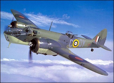
Fourth prototype Beaufighter R2055 with Vickers S and Rolls-Royce 40mm guns, Duxford 1941
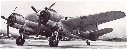
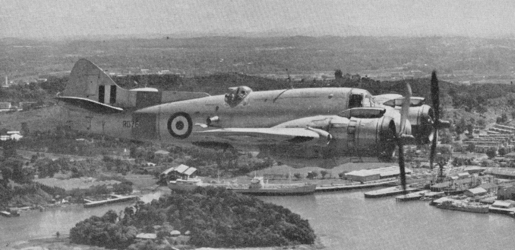
The first of four radar-equipped night fighter prototypes flew on 17 July 1939 and the first production Beaufighters were delivered to the Royal Air Force in the following April. The type was the first high performance night fighter equipped with airborne interception radar and successfully operated against the German night raids in the winter of 1940-1941. The twin-engine fighter utilized a crew of two men and was initially fitted with 4 x 20mm cannon and 6 x 7.7mm machine guns. Since the Beaufighter utilized many components of the already-in-production Beaufort torpedo plane, the implementation of the Beaufighter was quick. The Type 156 was based on the wings, tail unit, and landing gear of the Beaufort torpedo bomber with a new fuselage and Hercules radial engines. Production of the Beaufighter was launched on three lines.
The first night fighter success with AI.Mk IV radar followed in November 1940.
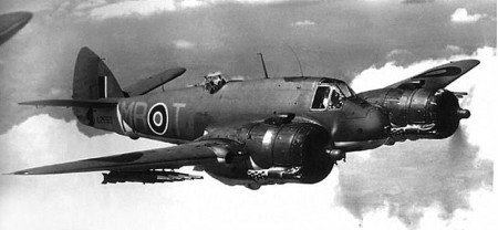
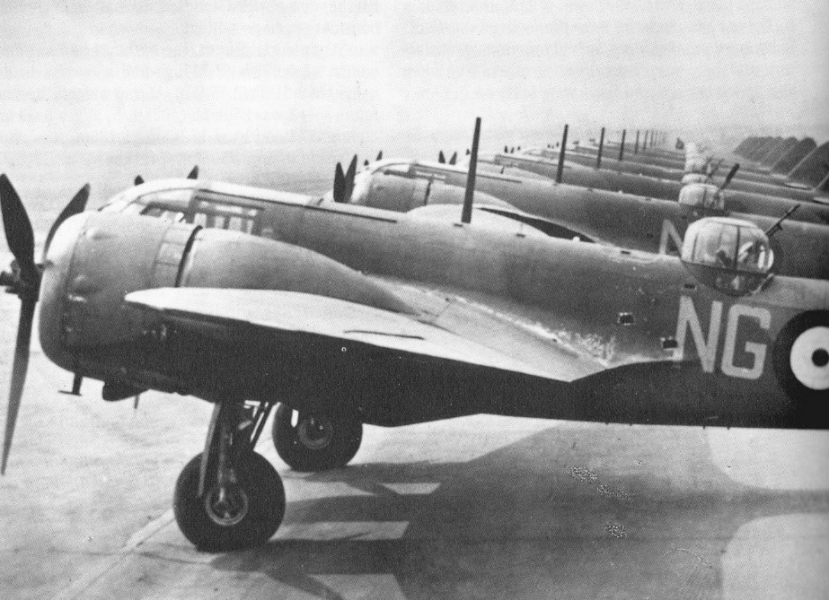
The Beaufighter Mk IIF (597 night fighters) had a dihedralled tailplane to avoid directional instability and 1,280-hp/954-kW Rolls-Royce Merlin XX inline engines to avoid overtaxing Hercules production. Later the Beaufighter was introduced into Coastal Command as a strike fighter. Its original gun armament was retained but rockets and torpedoes were added giving it an even greater fire power. Not only did the Beaufighter operate in North West Europe but also the Middle and Far East. For operations in the Mediterranean theatre, some Beaufighter Mk IFs were tropicalized and fitted with additional fuel tankage.
The USAF utilized the Bristol Beaufighter platform for a time as their primary nightfighter until an American-made alternative could be produced.
A total of 5564 aircraft were built in England and 364 built in Australia, by the time the last UK built one was delivered in September 1945 and fifty-two operational Royal Air Force squadrons had been equipped with the type. The last Australian Mk.21 (first flown 26 May 1944) delivery was in December 1946
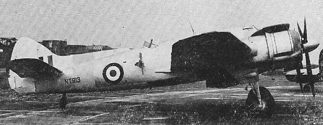
Of the 5562 built when production ended in September 1945, 2231 were Beaufighter Mk.10s and many were converted to target tug duties. Modifications included removal of most of the combat equipment, the installation of a target towing winch on the starboard side of the fuselage, together with a seat for the winch operator.
Beaufighter TT.10
The last flight of the type in Royal Air Force service took place on 17 May 1960 when a TT10 made a final target towing flight from Seletar.
RAF Beaufighter final flight – broken up for scrap hours later
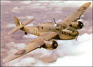
Beaufighter Mk IC 397 Coastal Command strike fighters
Beaufighter Mk IF two-seat night fighter. Engines: two 1,590-hp (1,186-kW) Bristol Hercules VI radial Maximum speed: 306 mph (492 km/h) at sea level Initial climb rate: 1,850 ft (564 m) per minute Service ceiling: 28,900 ft (8,810 m) Range: 1,500 miles (2,414 km) Weights empty: 14,069 lb (6,381 kg) Maximum take-off: 21,100 lb (9,526 kg) Wing span: 57 ft 10 in (17.63 m) Length: 41 ft 4 in (12.60 m) Height: 15 ft 10 in (4.82 m) Wing area: 503.0 sq ft (46.73 sq.m) Armament: four 20-mm cannon and six 0.303-in (7.7-mm) machine guns.
Beaufighter Mk IIF 597 night fighters Engines: 2 x 1,280-hp/954-kW Rolls-Royce Merlin XX Wingspan: 57 ft 10 in / 17.63 m Length: 42 ft 9 in Height: 15 ft 10 in / 4.84 m Empty weight: 13,800 lb Seats: 2
Beaufighter VI Wingspan: 57 ft 10 in / 17.63 m Length: 42 ft 9 in Height: 15 ft 10 in / 4.84 m Empty weight: 14,900 lb
Bristol Beaufighter VIF Length: 41.34ft (12.6m) Width: 57.91ft (17.65m) Height: 15.88ft (4.84m) Maximum Speed: 333mph (536kmh; 289kts) Maximum Range: 1,479miles (2,381km) Rate-of-Climb: 1,923ft/min (586m/min) Service Ceiling: 26,519ft (8,083m; 5.0miles) Armament: 4 x 20mm cannons in under nose position 6 x 7.62mm machine guns in wings Accommodation: 2 Hardpoints: 2 Empty Weight: 14,619lbs (6,631kg) Maximum Take-Off Weight: 21,627lbs (9,810kg) Engines: 2 x Bristol Hercules VI 14-cylinder air-cooled sleeve radials, 1,635hp.
Beaufighter IX Wingspan: 57 ft 10 in / 17.63 m Length: 42 ft 9 in Height: 15 ft 10 in / 4.84 m Empty weight: 14,900 lb
Bristol Beaufighter TF. Mk X Engines: 2 x Bristol Hercules XVII, 1320kW / 1770 hp Props: 3 blade Take-off weight: 11431 kg / 25201 lb Empty weight: 7076 kg / 15600 lb Wingspan: 17.63 m / 57 ft 10 in Length: 12.7 m / 41 ft 8 in Height: 4.83 m / 15 ft 10 in Wing area: 46.73 sq.m / 503.00 sq ft Max. speed: 488 km/h / 303 mph Cruise speed: 217 kts / 401 km/h / 249 mph Service ceiling: 26,500 ft / 8077 m ROC: 1850 fpm / 564 m/min Range: 2366 km / 1470 miles Range w/extra wing tanks: 1750 miles Crew: 2 Armament: 2 x 20mm Hispano cannons, 7 x Vickers 0.303 / 7.7mm machine-guns Bombload: 1 torpedo and 2 x 113kg bombs
Beaufighter TT.10 Engines: 2 x Bristol Hercules 18, 1770 hp Wingspan: 57 ft 10 in Length: 41 ft 4 in Loaded weight: 21,250 lb Max speed: 285 mph Max cruise: 264 mph Range at 15,000ft: 1960 mi Range with target out: 1680 mi
The Blenheim had been designed, under the direction of Frank Barnwell, to provide the RAF with a high-speed light bomber, and a version had then been produced to provide the RAF with a replacement for the Hawker Demon turret fighter. The concept of a twin-engined multi-seat long-range fighter was to prove as flawed as the Boulton Paul Defiant.
The first all-metal cantilever monoplane of stressed-skin construction to enter production for the RAF, the Blenheim marked the beginning of a new era of equipment.
The Blenheim’s conversion from three-seat light bomber to heavy fighter in 1938 was prompted by what was considered as fully adequate. At the time of its introduction its performance allowed it to out-pace most contemporary service aircraft but early in the conflict it proved vulnerable to fighter attack, being deficient in defensive armament and armour, and performance.
The Bristol Type 142M provided armament, a bomb aimer’s position, internal bomb stowage and more powerful 626kW Mercury VIII radial engines. To make room for a bomb bay in the lower fuselage, the low-wing configuration of the civil Type 142 was changed to mid-wing for the military version, which became named Blenheim.
The prototype made its first flight on 25 June 1936, and initial deliveries went to No 114 Bomber Squadron in March 1937.
The requirement for longer range led to evolution of the long-nosed, increased tankage and strengthened landing gear version, named originally Bolingbroke I. These began to enter RAF service in March 1939, by then designated Blenheim IV.
Blenheim IV
Twenty-four Blenheim IVs were delivered to the Finnish Air Force in 1939 and 50 were built under licence in Finland at the Valtion Lentokonetehdas (State Aircraft Factory) at Tampere.
After the Russian invasion of Finland in 1940, slowly reinforcements began to arrive for the Finnish air force. The first to come were 5 Gloster Gladiators, 12 Hurricanes, 17 Lysanders and 24 Blenheims, all from Britain. After that, 76 Morane-Saulnier and Koolhoven F.K. fighters arrived from France. Italy sent 17 Fiat fighters, Sweden 12 Gloster Gladiators, and the USA 44 Brewster Buffalo, of which however only 5 reached Finland in time. Even the Union of South Africa sent 25 Gloster Gladiators. Pilots and ground personnel from a number of countries also volunteered to assist them.
Blenheim Mk.IV
By the outbreak of World War II Blenheim Is had been superseded by Mk IVs in the UK, but remained in first-line service in Greece and the Western Desert. A Blenheim made the first aerial sortie of the war when, on 3 September 1939, a machine of No 139 Squadron made a photo reconnaissance flight over the German fleet in the Schillig Roads. On the following day Blenheims and Well¬ingtons joined in a mast height bombing of the pocket battleship von Scheer.
For the fighter role, the Blenheim was simply adapted from the standard Mk.I bomber by the addition of a ventral pack manufactured by the Southern Railway’s Ashford workshops, containing four 0.303in Browning guns plus 500 rounds of ammunition for each weapon. This supplemented the normal armament of a single wing-mounted Browning and a Vickers “K” 0.303 in a B.I. Mk.III semi-retractable hydraulically-operated dorsal turret. Some 200 Blenheims were modified to fighters, the first examples entering service with No,600 AAF Squadron at Hendon in September 1938.
Early operational experience with the Blenheim IF dictated the provision of a reflector sight, self-sealing tanks and some armour. No.23 Squadron undertook the first night intruder sortie of the war on 21-22 December 1939. On 5 June 1940 the Luftwaffe made its first night attack on London, and Blenheim IFs instituted nocturnal patrols which, on 18 June, resulted in the destruction of five bombers.
Meanwhile, the Blenheim IF had been closely involved in the development of airborne intercept radar. A flight of three aircraft of No.600 Squadron operating from Manston had performed operational trials with AI Mk.III radar, and on the night of 2-3 July a Blenheim IF from the Fighter Interception Unit at Ford gained the first kill with this radar. The Blenheim would equip the first ever night-fighting unit in the world for the No.25 Squadron.
Blenheim Is of No.603 Sqn, Northolt, April 1940
Subsequently the Blenheim IF became the prime night interceptor during 1940-41 and equipped six squadrons for Fighter Command in mid-1940 until supplanted by the Beaufighter.
1940 experimental reconnaissance variant – lightened and unarmed
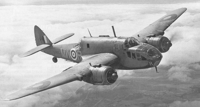
The Blenheim IV with which the RAF entered the second World War was an all metal monoplane powered by two Bristol Mercury radial engines, each giving 920 hp. Carrying a crew of three, the Blenheim had a span of 56 ft 4 in (17.17 m). Maximum speed was 262 mph (422 km/h) and range 1,800 miles (2,895 km). A 1,000 lb (454 kg) bomb load could be carried and defensive armament included a pair of guns in a dorsal turret.
On 24 February 1941 a modified Blenheim, known originally as the Bisley, made its first flight. Powered by two 708kW Mercury 30 engines, it featured an extensively modified nose and other changes. As the Blenheim V, a total of 940 production aircraft were eventually built in several variants. Although not popular with its crews it remained operational in the Far East until the latter part of 1943.
The Bolingbroke was the Canadian-built version of Bristol Aircraft (Britain) Company’s Blenheim Mk IV bomber. Bolingbrokes were manufactured by Fairchild Aircraft Ltd., Longueil, PQ. Canada built a total of 687 Bolingbrokes between 1939 and 1943.
The RCAF first used the Bolingbroke in 1939. In total, eight maritime squadrons in Canada flew the “Boly” on anti-submarine patrols off the east and west coasts. The majority of the Bolingbrokes served as training aeroplanes at the BCATP’s Bombing and Gunnery Schools and Wireless Schools.
Blenheim IF Engines: 2 x Bristol Mercury VIII, 840 hp Empty weight: 8840 lb / 4100 kg Loaded weight: 12.200 lb / 5534 kg Max speed: 237 mph / 381 kph at SL Max speed: 278 mph / 447 kph at 15,000 ft / 4572 m Cruise speed: 315 mph / 346 kph at 15,000 ft ROC: 1480 fpm / 451 m/min Time to 5000ft / 1524m: 3.9 min Time to 10,000ft / 3048m: 8.1 min Service ceiling: 24,600 ft / 7498 m Max range: 1050 mi / 1890 km Armament: 5 x 0.303in Browning guns / 1 x Vickers “K” 0.303in mg
Bristol Blenheim IF Engines: 2 x Bristol Mercury XV radial, 920hp. Length: 42.59ft (12.98m) Width: 56.33ft (17.17m) Height: 9.81ft (2.99m) Maximum Speed: 266mph (428kmh; 231kts) Maximum Range: 1,454miles (2,340km) Service Ceiling: 27,264ft (8,310m; 5.2miles) Armament: 1 x 7.7mm machine gun in wing system 2 x 7.7mm machine guns in manually-operated dorsal turret. Up to 1,000lbs of internal stores. Optional: 2 x 7.7mm rear-firing machine guns Accommodation: 3 Empty Weight: 9,800lbs (4,445kg) Maximum Take-Off Weight: 14,412lbs (6,537kg)
Bristol Engine 160 Blenheim Mk IV Engine : 2 x Bristol Mercury XV, 893 hp Length: 42.585 ft / 12.98 m Height: 9.843 ft / 3.0 m Wingspan : 56.332 ft / 17.17 m Wing area : 468.987 sqft / 43.57 sq.m Max take off weight : 14403.1 lb / 6532.0 kg Weight empty : 9792.4 lb / 4441.0 kg Max. speed : 231 kts / 428 km/h Cruising speed : 172 kts / 319 km/h Service ceiling : 27264 ft / 8310 m Wing load : 30.75 lb/sq.ft / 150.00 kg/sq.m Range : 1269 nm / 2350 km Crew : 3 Armament : 5x cal.303 MG (7,7mm), 454kg int, 145kg ext.
Blenheim IV Engines: 2 x Bristol Mercury, 920 hp. Wing span: 56 ft 4 in (17.17 m). Max speed: 262 mph (422 km/h). Range: 1,800 miles (2,895 km). Crew: 3. Bomb load: 1,000 lb (454 kg). Armament: 2 x mg.
Bristol “Blenheim Mk IV” Engines: 2 x Bristol Mercury XV, 675kW Take-off weight: 6532 kg / 14401 lb Empty weight: 4441 kg / 9791 lb Wingspan: 17.17 m / 56 ft 4 in Length: 12.98 m / 42 ft 7 in Height: 3.0 m / 9 ft 10 in Wing area: 43.57 sq.m / 468.98 sq ft Max. speed: 428 km/h / 266 mph Cruise speed: 319 km/h / 198 mph Ceiling: 8310 m / 27250 ft Range: 2350 km / 1460 miles Crew: 3 Armament: 5 x 7.7mm machine-guns, 600kg of bombs
Blenheim V Speed: 303 mph at 15,000 ft Operational range: 1900 miles Armament: 3 x .303 mg Bombload: 1000 lb
Bolingbroke Engines : Two 920hp Bristol Mercury XV, 920 hp Wing Span : 56ft 4in Length : 42ft 9 in Height : 12ft 10 in Speed : 266mph Seats: 3 Armament: One 0.303 Vickers K, four 0.303in Brownings. Four fixed brownings. 1000lbs bomb
On August 27, 1935, the RAF issued a requirement for a long-range high-speed torpedo-bomber. The Bristol Aeroplane Company responded to Design Specification M.15/35 by offering its three-seat Type 150, a development of its recent submission for a new four seat general reconnaissance aircraft, itself a stretched Type 142M.
On December 13 the Director of Technical Development disclosed Air Staff thoughts that a single design could combine the general reconnaissance (GR) and torpedo-bomber (TB) specifications, and on January 23, 1936, manufacturers were invited to submit proposals to Production Specification 10/36. Typical British logic decreed that the Blackburn Botha was the preferred design because Blackburn lacked work. However, its marginally higher fuel consumption and 436 Imp gal fuel capacity offered significantly less range than the 570gal of Bristol’s proposed Type 152 (named Beaufort in December), and it was accepted that a number of the latter would be needed for GR and torpedo squadrons based from Malta eastwards. One mandatory change was the addition of a fourth crew member, the price being a semi-exposed torpedo installation in both aircraft. Captain Frank Barnwell, Bristol’s chief designer, was killed shortly before the Beaufort’s first flight and Leslie Frise subsequently developed the type.
Bristol’s proposal to fit twin Browning 0.303in-calibre machine-guns in the gun turret was vetoed, as were twin Vickers drum-fed K guns. The special-to-type B.IV turret therefore had only one K gun, with 20 x 100-round ammunition drums. In May 1939, when the RAF wanted twin guns, the revised turret design was found unsuitable and the necessary modifications could not be incorporated until well into 1941.
The Air Ministry ordered 78 Bristol Perseus VI-engined Beauforts off the drawing board on August 1, 1936. There were to be no pre-production prototypes, the first five machines instead serving as development aircraft. Then on November 2, Bristol proposed a change of engine in order to restore performance eroded by weight increases, suggesting its own new and undeveloped twin-row 1,000 h.p. sleeve-valve Taurus. This was accepted in July 1937, allowing planning and production to proceed.
Except for wooden doors and fabric-covered control surfaces the Beaufort was of stressed-skin light alloy construction. The semi-monocoque fuselage, built in three sections, was shaped by lipped channel and Z section formers, multiple at the fuselage and other joints and other points of major stress, connected by angles-ection stringers.
Most construction was of Alciad or aluminium, but Hidaminium sections were used at the fuselage/fuselage and fuselage/wing joints. The front fuselage extended forward from the wing front spar and housed the pilot and navigator/bomb-aimer. Armour was fitted ahead of the instrument panel, but the V~windscreen, which incorporated clear vision panels and a ring-and-bead sight for the fixed gun(s), was unprotected. When fitted, the torpedo sight was above the pilot’s head.
The rear fuselage, strengthened near the turret and incorporating three heavy longerons, extended aft from the front spar to the stern frame and housed the Wireless Operator/Air Gunner (WOp/AG) and rear gunner. Aft of the radio compartment between wing spars was an armour plate partition and then the 27in-wide two-part main entrance hatch. Inside this was a chemical toilet, which doubled as a step. The long cabin was 54in wide. The fuselage was cut away in an inverted ‘V’ aft of the turret to improve the turret gunner’s field of fire. The stern frame carried the hori zontal and vertical tail surfaces and self-centring tailwheel. The latter retracted into a waterproof well, but was often locked down.
Bristol’s original design for the 100in-long bomb bay could not accommodate four Small Bomb Containers side-by-side with the bomb doors fully closed and so the lower fuselage was widened to 60in, giving it its characteristic bell-shaped cross section. Primarily designed to accommodate four 2501b anti-submarine bombs side-by-side, or two of the bulkier 2501b “B” or 5001b general purpose (GP) bombs, it was found on operations that combinations of two 2501b plus two 5001b GP/medium capacity (MC) bombs, tour slim 5001b semi-armour-piercing (SAP) bombs or four 2501b depth charges would fit. Fore-and-aft extensions formed the 19ft torpedo cell. A special rack could be fitted in lieu of bomb carriers to accommodate a torpedo, a magnetic mine or a 2,0001b bomb.
The RAF 28 aerofoil section cantilever wing was built in three main sections, with the outer panels bolted to the outer ends of the centre-section spars. The whole structure was based on two spanwise spars with full-depth webs and op and bottom extruded booms. The centre section was continuous through the fuselage, bearing all weights and forming the roof of the bomb bay. Square-section steeltube mounts on tubular bearers were fitted near the outer ends of its parallel spars for the engines and main undercarriage, which were housed in streamlined nacelles. Inboard of these between the spars were the two main 194 Imp gal fuel tanks.
A four-man inflatable dinghy was stored in the port wing root. The spars of the otherwise similar outer wing panels tapered and converged towards the detachable wingtips. Each housed an oil cooler and a 91 Imp gal fuel tank with a fuel jettison pipe, just outboard of which were pick-up points for an external 2501b bomb carrier. The leading edge of the port outer wing housed twin adjustable landing lights and inboard of these was a fixed 0.303in-calibre Browning gun with 300 rounds, The ailerons comprised alclad ribs on a tubular duralumin spar, and hydraulically-operated split flaps were fitted between these and the fuselage. Similar construction was used for the tail surfaces, and the elevators and rudder were similar to the ailerons.
The underslung engines driving 12ft-diameter de Havilland/Hamilton two-position propellers were in long cowlings with the exhaust collector rings forming the nosings. The undercarriage members retracted backwards hydraulically into the engine nacelles, the doors being closed by elastic cords.
The original two-gun armament soon proved inadequate and in mid1940 No 22 Sqn pioneered the installation of a Vickers K gun on each beam ahead of the turret for the WOp/AG’s use. The port gun fired through the entrance hatch, but the starboard gun had a more restrictive 12.5in aperture. A further but ineffective increase was the fitting of a rearward-firing Browning gun (600 rounds), sighted by mirrors and mounted in the nose emergency exit.
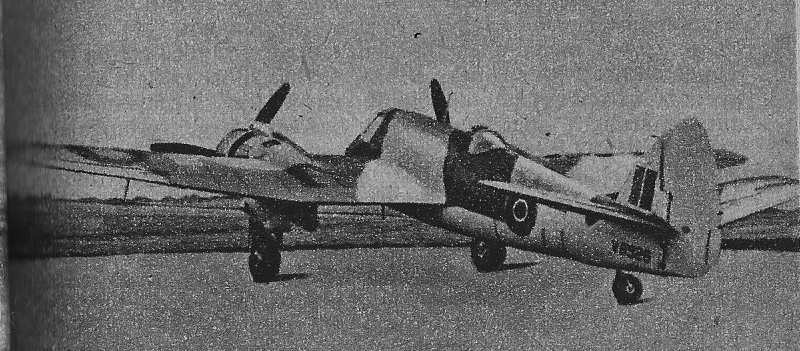
During August 1938 the first Beaufort (L4441), stressed to 17,0001b, underwent ground-running trials that revealed the serious overheating problems that would dog the Taurus throughout its life. Solutions were attempted and on October 15 Bristol’s chief test pilot, Capt Cyril Uwins, taxied L4441 for 10min and then took off for a first flight. This still revealed overheating and was cut short to 15min by severe tailplane vibration.
The next two short flights tested attempts to cure the tailplane and cooling problems and revealed that the latter were due to the inadequate airflow through the low-drag cowlings with their thrust- producing vertical cooling-air exit slots. Cooling was helped by fitting Blenheim-type cowlings with circumferential gills and by replacing the 7.5in oil coolers with 10.5in-diameter units, moved inboard by one rib space. Fuel jettison pipes for the outer tanks were also fitted.
Temporary tailplane bracing struts did not cure the vibration, but stiffer cockpit side windows did. A third problem involved handling difficulties when operating the undercarriage, owing to asymmetric drag caused by the aprons that closed the nacelles once the wheels were up. As the two oleos could not be made to raise or lower simultaneously a severe yaw developed. The aprons were removed to improve handling, but the now-open nacelles created considerable drag. Despite this, L4441 achieved 304 m.p.h. at 15,000ft during trials at the Aeroplane and Armament Experimental Establishment (A&AEE) at Martlesham Heath in April and May 1939 with fully supercharged Taurus III engines producing 1,060 h.p. at 3,300 r.p.m. using 87-octane petrol. Side~hinged undercarriage doors were fitted later, and the fuel jettison pipes were moved outboard, to be in line with the oil coolers.
The second Beaufort, L4442, which featured smaller undercarriage aprons, flew on June 29, 1939, both early machines having rounded lower nose windows. These proved weak and created visual distortions, and from L4443 (which flew on July 26) optically-flat windows were fitted.
The outbreak of war on September brought a change of plan; Beaufor were now needed for home-based TB and GR squadrons. The first five aircraft had been virtually handbuilt, but on October 25, L4446, the first fully jigged mass production aircraft, flew.
The third prototype, L4443, was shipped to Karachi for tropical trials which ran from February to May 1940 and involved cylinder and oil temperature checks with Taurus III and then Mk II engines. There were no overheating problem and the tests were concluded on May 21. It then flew home, reaching Filton on the 29th. To improve handling L4443 featured a revised rudder trim tab with the chord increased by 4in, increasing its area from 0.8 sq.ft to 1.25 sq.ft. This change was incorporated on all Beauforts.
Poor directional control dogged al UK-built Beauforts except the turret less trainers, so to overcome this the fin was slightly enlarged.
Production reached 30 aircraft a month during March 1940, but at the same time the A&AEE refused to clear the Beaufort for operational use because of “very bad single-engine flight characteristics”, Urgent improvements, including improved inter-cylinder baffles to help cooling, brought clearance by mid-April.
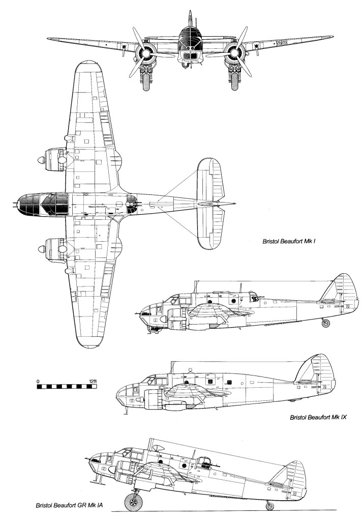
During the Mk.I production run the tailplane was modified to give a marked dihedral.
Mk.I
The presence of beam approach equipment was indicated by a long dipole aerial under the rear fuselage. On early aircraft the upper aerial for this equipment was housed within the radio mast, but later took the form of a blade aerial ahead of the turret. Semicircular trailing edge extensions were fitted behind the engine nacelles in mid-1941 to cure turbulence over the wing, This useful modification added 10 m.p.h. to the top speed but was not needed on the Mk II series, as the larger diameter Twin Wasp engines eliminated the turbulence. From W6537 onwards (the 410th UK-built machine) a Browning gun was installed in the starboard wing (500 rounds) and maximum permitted take-off weight raised from 20,000 to 21,0001b, by when the armoured bulkhead had been replaced by armoured seat backs for the pilot and WOp/AG. From the summer of 1941, 22 Sqn began to fit a Vickers K gun firing forward in the upper nose.
When all Beauforts were grounded during the late summer of 1940 in order to replace the troublesome Taurus III engines with a modified version of the moderately supercharged Taurus II using 100-octane fuel and now producing 1,130 h.p., the opportunity was taken to make all five fuel tanks self-sealing and to fit armour to the rear spar to protect the four fixed tanks. Frequent schemes for more armour, which offered some protection from fighters but little against flak, had always to be set against the need for new operational equipment, both exacerbating the type’s weight problems.
All Taurus engines featured singlestage superchargers and from then onwards used 100-octane fuel. The Taurus II had a low-speed impel which was cropped and ran at higher gear speed on the Mk VI. These two marks became the XII and XVI when the crankshafts, maneton joints, bearings and other features were modified for added reliability. Air Publication 3208 credits these four versions with a maximum output of 1130 hp at 3,100 r.p.m. There was a lack of uniformity between individual machines, especially before mid-1942.
Problems with the early Taurus engines, and Bristol’s desire to concentrate on the larger Hercules, led to the American Pratt & Whitney (P&W) Twin Wasp S3C4-G being adopted as an alternative. This was a two-stage engine producing 1,200 h.p. at 2,700 r.p.m., with the exhaust collected at the rear of the engine and emerging aft of the cooling gills. Propellers were 11 ft 6in fully feathering Curtiss Electrics. Beaufort Mk 1 N1110 was converted and flew as a prototype in November 1940. The 485 Mk Is were followed by ten interim Mk 11 aircraft; virtually Mk Is with Twin Wasp engines. Next came 45 production Mk IIs, which featured air-to -surface -vessel (ASV) radar. A small circular loop mounted in a streamlined housing replaced the large folding direction-finding (DF) loop. This was fitted to all future British TBs, although omitted from those later laid down as trainers. Jettison pipes for the inner fuel tanks were fitted at the rear of the engine nacelles.
The bombing of Daimler’s production line for the B. IV gun turret led to the adoption of the Bristol B.1 turret for future Beauforts. This was the Mk V, a well-armoured but nonretractable version of the Blenheim turret and carried twin Brownings with 950 rounds per gun. The next 110 Beauforts featured this, strengthened engine and undercarriage bearers and a thicker wing skin. The permitted underwing bomb load was doubled. With these modifications the aircraft became the M1k IIA. Heavy shipping losses in the Atlantic so reduced supplies of Twin Wasps that Taurus engines were installed in the next 529 machines, which were otherwise identical to the Mk IIA and designated Mk IA. These introduced twin nose guns which were fitted retrospectively to earlier machines. Once supplies of Twin Wasps permitted, the Mk IIA was reintroduced and 129 more torpedo bombers were built. With requirements met, a final batch of 121 machines was laid down as unarmed dual-control advanced trainers. A few torpedo-bombers were also converted to trainer standard.
In the UK all Taurus engines and major airframe components were manufactured at Bristol’s works. Bristol B.IV gun turrets were manufactured by the Daimler Car Company and Bristol B.1 turrets by the Brockhouse Company. Most Beauforts were assembled at Filton and flown out from there. However, to provide space for the new Buckingham, the final 250 were assembled at Bristol’s shadow factory at Banwell from stockpiled parts and flown out from Oldmixon after completion. Twin Wasp engines for the 415 Mk ll-series aircraft were all imported from the USA.
A planned twin-float Beaufort for Australia and Canada was not built; neither were the projected Mk III with Rolls-Royce Merlin engines, nor the Mk IV with improved Taurus XX engines, in both cases because the engines were not available. The M1k III was originally to have had the Merlin XX, but it was quickly appreciated that the Mk 30 was more suitable. However, Rolls-Royce had not developed a twin installation version and the whole scheme lapsed. The Taurus XX engine, with two-speed blowers and fully-feathering propellers, was flight tested in AW372, which featured an Australian-style enlarged fin. This was not a true prototype Mk IV, however, as it lacked the intended B.15 four-gun turret, eventually flight tested in EK997. It was intended that the final 500 Beauforts would be Mk IVs, but Bristol lacked the capacity to produce the Taurus XX engines. An enlarged fin was also fitted to AW304, a widely-used trials machine.
Coastal command’s first Beaufort, L4447, joined 22 Sqn at Thorney Island on November 15,1939. After delays caused by engine problems operations began on April 15, 1940, laying magnetic mines in the German Bight. Bombing attacks against land and sea targets commenced in May with the first British 2,0001b armour piercing (AP) bombs being dropped on the 7th against minor vessels.
Even before the war had started, it had been agreed that Australia’s Department of Aircraft Production (DAP) would supply the Royal Australian Air Force and overseas-based RAF units with Beauforts.
In March 1937 the RAAF ordered the Bristol Bolingbroke (the proposed General Reconnaissance development of the Blenheim mark I), the design was cancelled in December 1937 and in February 1938 the RAAF Bolingbroke order was changed to Beaufort, and in March 1938 it was agreed that Australia would build Beauforts for the RAAF and for overseas-based RAF units.
To assist local production two complete airframes and 20 complete sets of airframe parts were promised by Bristol, who trained 78 key Australian personnel and sent 20 of their staff to Australia. Bristol’s customary tardiness caused delays, but on October 20, 1939, Beaufort L4448, which had been built without engines, at last left Filton for Australia. Component production for the Australian Beaufort would be spread among plants in south-eastern Australia, with final assembly at Fishermen’s Bend in Victoria and Mascot, New South Wales, all under the control of the Beaufort Division of the Department of Aircraft Production (DAP).
In April 1940, by which time it had been decided that all Australian Beautorts would have Twin Wasp engines, reassembly of L4448 was under way, with the Commonwealth Aircraft Corporation responsible for fitting its engines. However, Britain’s desperate war situation forced an embargo on the export of strategic materials and progress on completing the Beaufort and converting it to take the new engines was slow: the promised second machine, L9811, was not supplied.
The original order from 1939 was 90 for the RAF then 90 for the RAAF. The RAF order was increased in March/April 1941 by another 90, making 270 on order as more Hudsons were unavailable. Approval for a further order of 180 Beauforts came on 16 July 1942 then another 250 in February 1943. Grand total 700.
Although the UK’s export embargo was lifted by the end of 1940, the bombing of Bristol’s works continued to hinder all forms of assistance to Australia, as did the sinking of ships carrying supplies from the UK and USA. Until local production was in full swing Australia had to import such key items as engines and propellers.
On May 5, 1941, L4448 made its first flight, and T9540, the first Australian Beaufort built from imported parts and the first of the RAF order, flew on August 22 from Fishermen’s Bend, achieving a speed of 271 m.p.h. on test.
Production at Mascot was delayed and its first machine, T9545, did not fly until October 20. The first Beauforts arrived in December, but they were not fully equipped, at 100 Sqn, the RAF’s Australian detachment, Singapore. Most were built as GR Bombers but a number were completed to GR Torpedo standard, all designated Mk 11. Following the transfer of 100 Sqn and its 17 aircraft (two having been lost) to the RAAF, Britain allocated its order for 90 Beauforts to Australia. A change to RAAF A9 series serial numbers began before this order had been completed.
Basic design and construction followed UK practice, the most significant change being the enlargement of the fin from 11 .4 sq.ft to 14.3 sq.ft to improve stability, The mainwheels were fully enclosed by additional doors at the rear of the engine nacelles, The use of ball bearings was reduced by some 50 per cent.
Before February 1942 most Beauforts, including those sent to Singapore, were unnecessarily fitted with the semi-circular trailing edge extensions typical of Taurus-engined machines, The fitting and later deletion of chin guns, the fitting of nose guns and the change of gun turret followed British practice, but the DAP also fitted a forward-firing Vickers K gun in a glazed section of the cabin roof above the beam guns.
After completion of the first 50 aircraft a temporary shortage of P&W S3C4-Gs led to S1C3-G single-stage engines being fitted to the next 100, degrading their altitude performance, A subsequent shortage of Curtiss Electric propellers led to the second 90 aircraft being fitted with de Havilland/Hamilton units, as fitted to Taurus-engined machines.
In RAAF service the first batch became the Mk V; the next 40, with non-standard engines and Australian ASV radar, became the Mk V1; the next 60, with both non-standard engines and propellers, the Mk VII and the next 30, with non-standard propellers, the Mk VA (Mk VIII having already been allocated to a new definitive version similar to the British Mk IIA). Twin nose guns were being fitted to service aircraft in August 1942, the mark VIII appeared in November. The 520 Mk VIIIs featured twin nose-guns, fitted retrospectively to earlier marks, and many Mk VIIIs from the A9-54X-range onwards received 0.5in-calibre wing guns.
Major crisis was caused during 1943 by the failure of locally produced Breeze actuators for elevator trim tabs. These had been manufactured from unsuitable materials and were found to have been the cause of a large number of fatal crashes.
Although early supplies of Twin Wasps were imported from the USA, General Motors (Holdens) manufactured 870. Final assembly was at Fishermen’s Bend (A9-odds) and Mascot (A9-evens, although 451 was built there). Peak output reached 37 in September 1943.
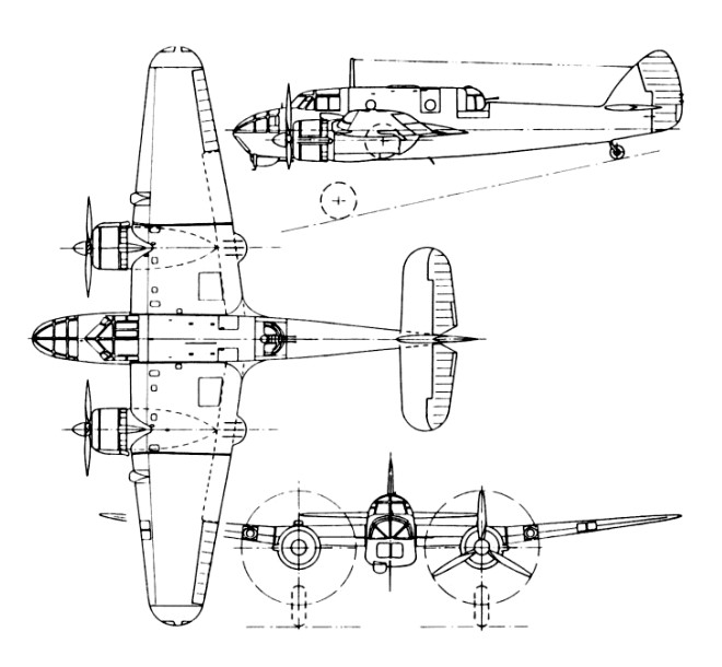
During 1944 some 46 airframes, mainly Mk VIIIs, were reconstructed as Mk IX transport aircraft, with their turrets and military fittings removed, with the exception of bomb shackles, and the fuselage top line raised aft to provide space for five airliner-type seats. Virtually new, these were given new serial numbers. The last, A9-746, was delivered in October 1945. All marks of Beaufort remained Bristol Type 152.
The transfer of the RAF’s No 100 Sqn to the RAAF was announced on February 28, 1942 (made retrospective to the 25th). The transfer was seamless and the RAF pattern of shipping escort and anti-raider patrols continued. The first offensive mission was flown on May 27, when two Beauforts staged through Port Moresby, New Guinea, to reconnoitre the Deboyne Islands.
Four weeks later two Beauforts of another detachment bombed shore targets at Salamaua on New Guinea while five others bombed a ship reported as under way off Lae in north-eastern New Guinea, but what was in fact the wreck of the Tenyo Maru, which had been beached after bombing by US Navy aircraft on March 10.
In the shape of No 489 Sqn, an Article XV unit within RAF Coastal Command, the Royal New Zealand Air Force received six Beaufort Mk Is between August and October 1941. However, various crises overseas led to these being withdrawn by the following April before the unit could become operational.
The early story of No 415 Slain Article XV unit of the Royal Canadian an Air Force (RCAF), was similar to that of 489 Sqn. At Sidney, Vancouver Island, the metropolitan RCAF took over the Beauforts of the RAF’s 32 OTU to form the emergency 32 Sqn RCAF, and used them on torpedo and bomb-armed anti-shipping searches over the eastern Pacific at the time of the Japanese attack on Pearl Harbor in December 1941. This was repeated during May and June 1942 when the Aleutian Islands were attacked and Canada threatened. The RCAF formed its own 149 (TB) Sqn with the 12 surviving Beauforts at the same base in November 1942, retaining them until August 1943 without becoming operational.
From January 1942, 18 Beaufort Mk Is joined the South African Air Force (SAAF), equipping 36, 37 and HO Flights in the Union, Patrols over the southern oceans were flown before the numbered Flights took part in the capture of the Diego Suarez area of Madagascar in May. Before the subsequent occupation of the whole island the two Flights were amalgamated, together with No 32 Sqn’s Martin Marylands, to form 20 Sqn in July. This unit was in turn renumbered No 16 Sqn SAAF in September. The Beauforts fared badly because there were no spares on the island and the SAAF was still imposing the outmoded maximum take-off weight of only 18,5001b.
Before the ten surviving Beauforts were returned to the RAF a few had served with other units in the Union. Meanwhile 16 Sqn had converted to Blenheim Vs and moved to North Africa as an A/S patrol unit. During June 1943 the Blenheims made way for a mixed complement of Taurus and Twin Wasp-engined Beauforts. These flew patrols over the central Mediterranean before reequipment at the turn of the year.
The Royal Navy’s Fleet Air Arm (FAA) received more than 100 Beauforts, Numerous Beaufighter lls had been made available to 7XXseries Fleet Requirements Units, but as these proved difficult to master by pilots trained on Blenheims, an interim dual-control trainer was sought, The RAF provided six Beaufort 1As, which, after modification to FAA standard, joined 798 Sqn at Lee-on-Solent in October 1943. The unit was renumbered 762 Sqn in March 1944 and moved to Dale, converting to Beaufort T.IIA trainers, the last retiring in March 1946. The station flight at Yeovilton used three M1k 1As between October 1944 and February 1945. Far more Beauforts were used overseas than at home, all being Mk 1As. From January 1944 onwards, 733 Sqn in Ceylon received about 14 at RAF Minneriya and later China Bay, initially from RAF stocks; all had gone by July 1945.
On Malta 728 Sqn received about 15 from September 1944, retaining them for exactly a year, and 779 Sqn received two or three at Gibraltar during November 1944. Although there is no confirmation of actual receipt, 775 Sqn at Dekheila, Egypt, and 788 at Port Reitz, Kenya, also had Beauforts on their inventories.
The Turkish Air Force (TuAF) was the last service to receive Beauforts. Ordering 18 (possibly 21) in 1943, there is still doubt as to how many were received. Although RAF records list 13 M1k 1As and 12 Mk 11As supplied from North African MUs during 1944 and 1945 respectively, TuAF aircraft lists contain 46XXseries serial numbers for only 11 Mk 1As and ten M1k 11As. However, a separate list of accidents contains the serial numbers of an additional eight Beauforts, at least four of them 1As: the other four have out-of-series 59XX-range serial numbers. With no torpedoes available the Beauforts were initially used as GR bombers by two squadrons of the 105th Torpedo & Reconnaissance Group. The few M1k 11As that survived until 1947 were modified locally to trainer standard by Bristol’s resident engineers and used to convert pilots on to Beaufighter M1k Xs at lzmjt. Precise dates are lacking, but all the Beauforts had gone by the end of 1950 at the very latest.
Total Beaufort production was 1380, including 700 built in Australia.
Beaufort Mk.I Engines: 2 x Bristol Taurus II or VII, 1130 hp Propellers: 12 ft 0 in constant speed Wingspan: 57 ft 10 in / 17.62m Chord at root: 11 ft 4 3/8 in Dihedral (outer wing only): 6.5 degs Length: 44 ft 2 in / 13.49m Height (prop tip): 13 ft 7 in Mainwheel track/ engine centre: 18 ft Tailplane span: 18 ft 4 in Wing area: 503 sq.ft / 46.73 sq.m Aileron area: 26.6 sq.ft Fin area: 11.4 sq.ft Rudder area: 25.7 sq.ft Tailplane area: 52.8 sq.ft Elevator area: 32.6 sq.ft Flap area: 57.1 sq.ft Fuel: 570 Imp Gal + 138 Imp Gal Empty weight: 12,373 lb MTOW: 18,500 lb Wing load: 42.23 lbs/sq.ft / 206.0 kg/sq.m Maximum Speed: 265mph (426kmh / 230kts) at 6,500 ft Cruise speed: 175 mph at 15,000 ft Range: 990 miles Maximum Range: 1,600miles (2,575km) Service Ceiling: 16,499ft (5,029m) Armament: 2 x 7.7mm machine guns in nose 2 x 7.7mm machine guns in dorsal turret Maximum bombload of up to 2,000lbs. 1 x 1,605lb 457mm torpedo 1 x 7.7mm rear-firing machine gun under nose 2 x 7.7mm machine guns in beam positions Bombload: 2000 lb internal / 500 lb external / total max 2200 lb Crew: 4
Beaufort Mk.IA Engines: 2 x Bristol Taurus XII or XVI, 1130 hp Propellers: 12 ft 0 in constant speed Wingspan: 57 ft 10 in Chord at root: 11 ft 4 3/8 in Dihedral (outer wing only): 6.5 degs Length: 44 ft 2 in Height (prop tip): 13 ft 7 in Mainwheel track/ engine centre: 18 ft Tailplane span: 18 ft 4 in Wing area: 503 sq.ft Aileron area: 26.6 sq.ft Fin area: 11.4 sq.ft Rudder area: 25.7 sq.ft Tailplane area: 52.8 sq.ft Elevator area: 32.6 sq.ft Flap area: 57.1 sq.ft Fuel: 570 Imp Gal + 138 Imp Gal Empty weight: 13,362 lb MTOW: 21,000 lb Max load: 21,593 lb Max speed: 247 mph at 5,000 ft Cruise speed: 136 mph at 5000 ft Range: 1605 miles Armament: 2000 lb internal / 1000 lb external / total max 2200 lb. 2-10 .303 mg.
Beaufort Mk.II Engines: 2 x P & W Twin Wasp S3C4-G, 1200 hp Propellers: 11 ft 6 in full featuring Wingspan: 57 ft 10 in Chord at root: 11 ft 4 3/8 in Dihedral (outer wing only): 6.5 degs Length: 44 ft 2 in Height (prop tip): 13 ft 1 in Mainwheel track/ engine centre: 18 ft Tailplane span: 18 ft 4 in Wing area: 503 sq.ft Aileron area: 26.6 sq.ft Fin area: 11.4 sq.ft Rudder area: 25.7 sq.ft Tailplane area: 52.8 sq.ft Elevator area: 32.6 sq.ft Flap area: 57.1 sq.ft Fuel: 570 Imp Gal + 138 Imp Gal Empty weight: 12,760 lb MTOW: 21,000 lb Max load: 21,240 lb Max speed: 271 mph at 6,000 ft Cruise speed: 155 mph at 5000 ft Range: 1410 miles Armament: 2000 lb internal / 500 lb external / total max 2200 lb. 2-10 .303 mg. Beaufort Mk.IIA Engines: 2 x P & W Twin Wasp S3C4-G, 1200 hp Propellers: 11 ft 6 in full featuring Wingspan: 57 ft 10 in Chord at root: 11 ft 4 3/8 in Dihedral (outer wing only): 6.5 degs Length: 44 ft 2 in Height (prop tip): 13 ft 1 in Mainwheel track/ engine centre: 18 ft Tailplane span: 18 ft 4 in Wing area: 503 sq.ft Aileron area: 26.6 sq.ft Fin area: 11.4 sq.ft Rudder area: 25.7 sq.ft Tailplane area: 52.8 sq.ft Elevator area: 32.6 sq.ft Flap area: 57.1 sq.ft Fuel: 570 Imp Gal + 138 Imp Gal Empty weight: 14,032 lb MTOW: 21,500 lb Max load: 22,236 lb Max speed: 255 mph at 6,500 ft Cruise speed: 136 mph at 5000 ft Range: 1470 miles Armament: 2000 lb internal / 1000 lb external / total max 2200 lb. 2-10 .303 mg.
Beaufort Mk.V Engines: 2 x P & W Twin Wasp S3C4-G, 1200 hp Propellers: 11 ft 6 in full featuring Wingspan: 57 ft 10 in Chord at root: 11 ft 4 3/8 in Dihedral (outer wing only): 6.5 degs Length: 44 ft 2 in Height (prop tip): 13 ft 1 in Mainwheel track/ engine centre: 18 ft Tailplane span: 18 ft 4 in Wing area: 503 sq.ft Aileron area: 26.6 sq.ft Fin area: 14.3 sq.ft Rudder area: 25.7 sq.ft Tailplane area: 52.8 sq.ft Elevator area: 32.6 sq.ft Flap area: 57.1 sq.ft Fuel: 570 Imp Gal + 138 Imp Gal Empty weight: 12,990 lb MTOW: 21,000 lb Max speed: 264 mph at 6,900 ft Cruise speed: 162 mph at 5000 ft Range: 1410 miles Armament: 2000 lb internal / 500 lb external / total max 2200 lb. 2-10 .303 mg.
Beaufort Mk.VIII Engines: 2 x P & W Twin Wasp S3C4-G, 1200 hp Propellers: 11 ft 6 in full featuring Wingspan: 57 ft 10 in Chord at root: 11 ft 4 3/8 in Dihedral (outer wing only): 6.5 degs Length: 44 ft 2 in Height (prop tip): 13 ft 1 in Mainwheel track/ engine centre: 18 ft Tailplane span: 18 ft 4 in Wing area: 503 sq.ft Aileron area: 26.6 sq.ft Fin area: 14.3 sq.ft Rudder area: 25.7 sq.ft Tailplane area: 52.8 sq.ft Elevator area: 32.6 sq.ft Flap area: 57.1 sq.ft Fuel: 570 Imp Gal + 138 Imp Gal Empty weight: 14,070 lb MTOW: 22,500 lb Max speed: 268 mph at 14,500 ft Cruise speed: 178 mph at 5000 ft Range: 1450 miles Armament: 2000 lb internal / 1000 lb external / total max 2200 lb. 2-10 .303 or .50 mg.
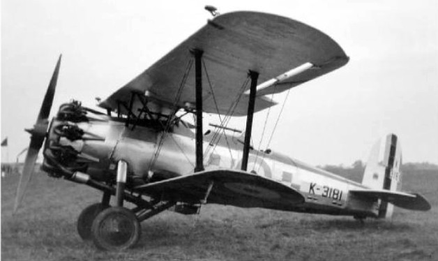
In 1926, the British Air Ministry issued F.9/26 specification for a radial-piston engine fighter design that could operate during the day or night, armed with twin Vickers-type machine guns, and capable of engaging the top enemy bombers of the day. Bristol responded with the Bulldog I as a private venture, designed by Frank Barnwell, which was used as a developmental model to ultimately become the Bulldog II.
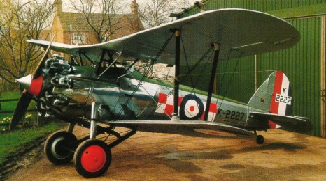
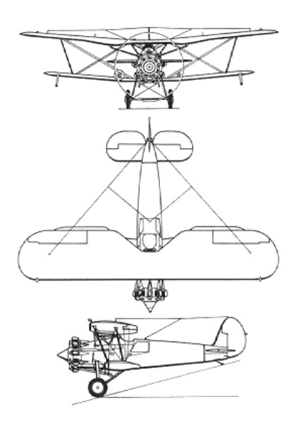
The Bristol Jupiter engine, which in the initial production Bulldog II was a 328kW Jupiter VII, was mounted in a streamlined nose with its cylinders projecting uncowled but with streamlined fairings and cooling baffles. The propeller had two wooden blades. Features included Frise ailerons on the large upper wing and an adjustable trimming tailplane.
The Bulldog II had an all-metal fuselage with a fabric skin covering. The biplane wings were equal span with single bays and a single pair of parallel support struts. Armament consisted of 2 x 7.7mm Vickers machine guns with their breeches accessible to the pilot, synchronized to fire through the spinning propeller via an interrupter gear. Four 9 kg bombs could be carried under the small lower wing.
The undercarriage was fixed with a tail skid and both were designed to operate from grass runways. The pilot sat behind and underneath the upper wing in an open cockpit, with an oxygen supply for high altitudes and a short-wave two-way radio. Optional armament included 4 x 20lb bombs under the wings.
From the first flight on 17 May 1927, it was entered in the F9/26 competition at Martlesham Heath against the officially sponsored Armstrong Whitworth Starling, Boulton-Paul Partridge, Gloster Goldfinch and Hawker Hawfinch. The Bulldog was well liked by the RAF test pilots and could be dived to terminal velocity without damage to its robust steel structure. The only criticism involved the spin recovery which was overcome with a longer fuselage, larger fin and rudder.
Because of the closeness of the competition between the Bulldog and the Hawfinch the British Government ordered a single Bulldog II for further trials. The Bulldog II had a longer rear fuselage to overcome the spin deficiency of the prototype. First flown on January 21, 1928, the Bulldog II was tested against the Hawfinch at Martlesham, but the competition proved so close that a final decision was reserved until service pilots could assess both types. Eventually the decision was based on the ease of maintenance and here the Bulldog, with its single bay wings as against the twin bay wings of the Hawfinch, won. This Mk II prototype modification made cross wind landings and taxiing more difficult.
Nine Bulldogs were ordered, deliveries to 3 Squadron RAF, starting on May 8, 1929.
The first batch comprised 25 aircraft, of which 23 went to RAF fighter squadrons beginning with No 3 in 1929. Altogether 92 Bulldog II were built, one of which was retained for trials with Mercury engines in more advanced forms of cowling. Seventeen went to Latvia, eight to the RAAF, two to the US Navy, two to Siam, 12 to Estonia, three to Sweden and one to Chile.
US Navy A8607 at Anacostia 3 June 1930
In 1930 the two Bulldogs were purchased for evaluation by the US Navy, at the same time as one was supplied to the Imperial Japanese Navy. Both USN Bulldog IIAs, powered by Bristol Jupiter VIIF engines, were shipped in crates from Filton via Avonmouth Docks. The US Navy makings were applied on reassembly, the Bulldogs being supplied directly from the production line. The first, c/n 7358, left England on 10 October 1929, but developed aileron flutter and wing rib failure during the prescribed terminal velocity diving sequence. The Second. c/n 7398 left England on 24 February 1930, had revised aileron mass balance and strengthened wing ribs.
The Bulldog II entered RAF service in June of 1929 and effectively replaced the aging Gloster Gamecock and Armstrong Whitworth Siskin fighters then in frontline use. It was successively upgraded, the Bulldog IVA with the Bristol Mercury VIS 2 engine being the last version to be built in quantity.
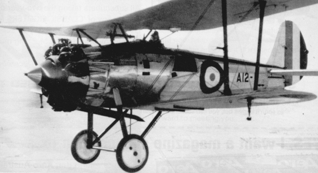
A civil demonstrator flown in June 1930 was stressed for greater gross weight and led to the main production version, the Bulldog IIA, the usual engine of which was the 365kW Jupiter VIIF with forged cylinder heads. By November 1933 Bristol had built 262 of this model, of which eight went to Sweden and 253 to the RAF. Four more, called Bristol 105D, were supplied to Denmark with Madsen guns and other changes. Two improved and much faster aircraft with the Mercury engine and Townend ring cowl were designated Bulldog IIIA, leading to the strengthened four-aileron Bulldog IVA, with a 477kW Mercury VIS2 and full-length cowl. This was beaten by the Gladiator for RAF orders, but 17 were built for Finland in the first two months of 1935. The Australian Air Board approved the purchase of the six Bulldogs on Januany 17, 1929, at an estimated cost of £34,700. In May it was noted that Order No.244 was “held up in London owing to argument between Air Ministry, our Liaison Officer and the Bristol Company in regard to price.” The RAAF had previously used a two scat SE.5a to introduce pilots to single seat fighters and was interested in increasing the order by adding a two seat Bulldog. The Liaison Officer had to advise that the type was not being constructed for preliminary instruction for single seat fighters, two seat Armstrong Whitworth Siskins were standardised for this purpose. It was now evident that funds for the eight were available and as it was thought that a better price per unit could be obtained for a larger number, Order No.277 was raised to cover two additional Bulldogs. These aircraft were identical to the RAF Bulldog II except for the choice of engine and supplied under Air Ministry Contracts No.901228/29 for aircraft, and 934691/29 for engines respectively. “As supplied to the Royal Air Force (the Bulldog) is fitted with a Jupiter Mk VII (supercharged) engine for speed at heights above 10,000ft, but as operations at these heights are not called for in our case, as the ‘Bulldog’ with Mk VI is faster than with the Mk VII below 8,000ft,” the RAAF ordered the Bulldog with the Jupiter VI engine. The eight Australian Bulldogs (Bristol construction sequence numbers 7389 7396) were allocated the serials A12 1 to A12 8. The price quoted for each was £3,750. They arrived in Melbourne, Victoria, aboard the SS Fordsdale on March 14, 1930. Assembly took place at 1 Air Depot, Laverton, and the first was flight tested by F/Lt F R W Scherger on May 1.
RAAF Bulldog
RAAF Bulldogs entered service in 1930. Equipping No 1 Sqn at Point Cook, five of the eight were lost in crashes. One of these resulted in the first recorded RAAF pilot successfully bailing out, after an attempted outside loop caused a structural problem.
The Bulldog was constructed of ribbon steel worked up into suitable corrugated sections. The process was not in operation in Australia and major spares were necessarily obtained from overseas, but items “such as tanks, metal fittings and small parts… [were] obtained locally.” The upper wings were of greater span and chord than the lower wings. All fuel was carried in two gravity tanks recessed into the upper wings. The undercarriage featured oleo dampened rubber in compression legs which were attached to the top longerons. Two Vickers guns were mounted on each side of the cockpit. Provision was made for a wireless transmitter receiver to be carried in a compartment just behind the cockpit. The last Bulldog was an all-stainless-steel Mk IIA for the Air Ministry.
Bulldog II’s would never saw combat in British service but foreign users of the type did. Finnish pilots used Bulldogs against Soviet invaders in World War 2. Other foreign operators included Spain. In 1931 a Mk IIA had been rebuilt into a dual-control advanced trainer. In December 1932 a modified trainer, called Bulldog TM (Training Machine), went into production as a standard type for the RAF. By December 1934 no fewer than 60 had been delivered. They were designed so that by fitting different rear fuselages, and adding guns (for which provision was made), they became fighters. Bulldogs remained in full RAF service until 1937, and until 1940 with Baltic air forces.
Bulldog TM 23 June 1934 – TM3181, 450 hp Bristol Jupiter VI
Some 443 examples were produced from 1928 until 1935 including a total of 293 Bulldogs built for the RAF. The Bristol Bulldog was replaced in RAF service by the Gloster Gauntlet.
Nakajima of Japan produced two examples of the Bulldog as the J.S.S.F.
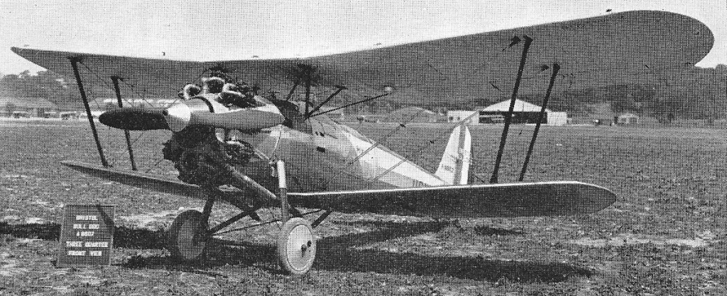
Engine: 1 x 650hp Rolls-Royce Condor III ake-off weight: 3690 kg / 8135 lb Empty weight: 2361 kg / 5205 lb Wingspan: 17.65 m / 57 ft 11 in Length: 14.48 m / 47 ft 6 in Height: 4.37 m / 14 ft 4 in Wing area: 91.51 sq.m / 985.00 sq ft Max. speed: 193 km/h / 120 mph Ceiling: 5456 m / 17900 ft Range: 1385 km / 861 miles Armament: 3 x 7.7mm machine-guns, 1 x 250kg or 2 x 100kg bombs
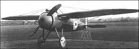
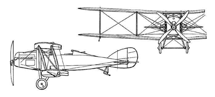
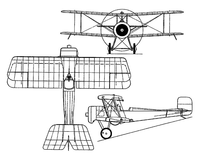
The prototype Bristol M.1A, designed by Frank Barnwell with a 110 hp Clerget engine, flew for the first time on 14 July 1916. Streamlined for its day, it reached a top speed of 132 mph.
Four M.1B’s were built for service trials, differing from the prototype only in having a pyramid-shape wing support structure, in place of the former curved cabane, and a 7.7mm Vickers machine-gun on the port side of their front fuselage and a clear-view cut-out panel in the starboard wing root to afford the pilot a measure of downward visibility.
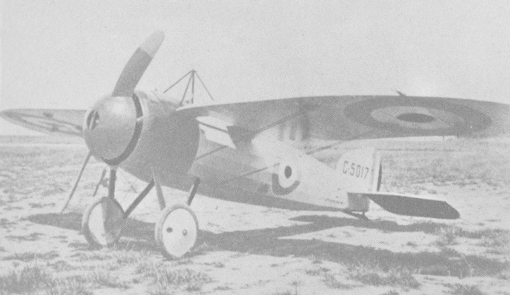
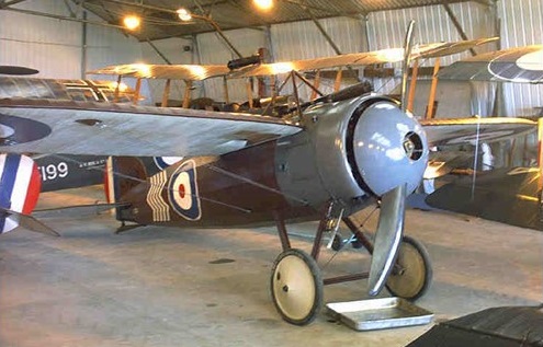
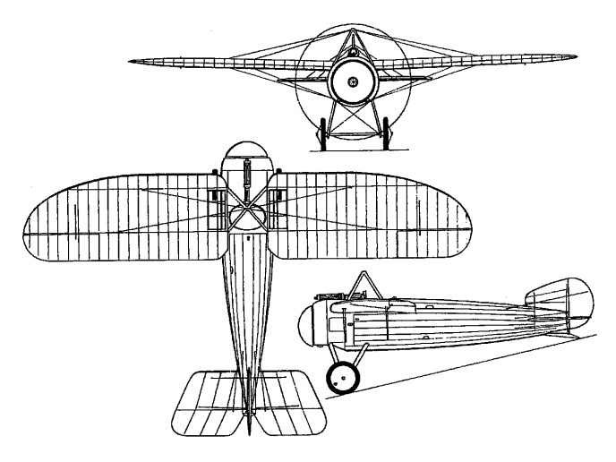
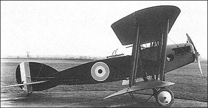
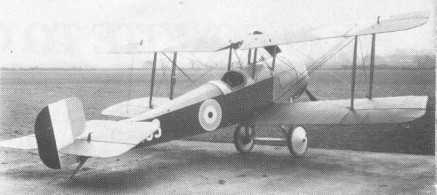
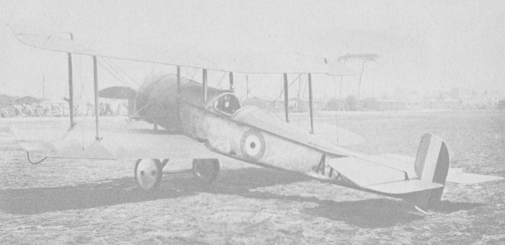
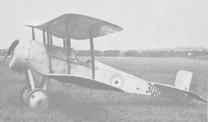
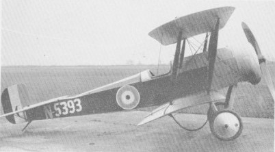
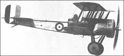
A production order for 125 aircraft was placed on 3 August 1917 as M.1s. Powered by a 110hp Le Rhone 9J nine-cylinder rotary engine, the M.1C had a centrally-mounted Vickers gun, but its subsequent operational career was largely confined to the Middle East where 33 M.1Cs were sent during 1917-18.
M .1C
Only five squadrons were partly equipped with the M1 for operational use although a number were issued to flying schools. No aircraft of this type were issued to RFC squadrons based in France, the 97km/h landing speed being considered too high for small Western Front airfields.
M.1C Engine: 110hp Le Rhone 9J nine-cylinder rotary Wingspan: 9.37 m / 30 ft 9 in Length: 6.23 m / 20 ft 5 in Height: 2.37 m / 7 ft 9 in Wing area: 13.47 sq.m / 144.99 sq ft Empty weight: 406 kg / 895 lb Take-off weight: 611 kg / 1347 lb Fuel capacity: 18 gal Max. speed: 209 km/h / 130 mph at SL Service ceiling: 20,000 ft Endurance: 1 hr 45 min Armament: 1 x Vickers 7.7mm mg Seats: 1
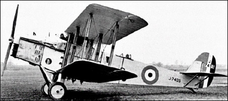
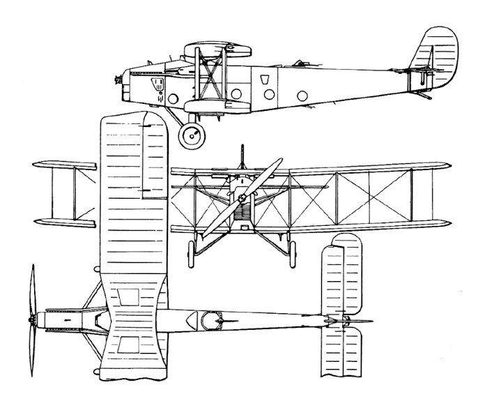
In March 1916 the design was begun of a 120 hp Beardmore powered tractor replacement for the B.E. pusher scouts. The type was desig¬nated R.2A and was intended to be armed with one wing mounted Lewis machine gun and another for the observer on a Scarff ring. At the same time a similar design using the 150 hp Hispano Suiza was produced, but lack of power from the Beardmore caused the designer, Captain Frank Barnwell, to produce a new design using the new 190 hp Rolls Royce Falcon and with the designation F.2A. This was an unequal span two bay biplane with its fuselage, tapered to the rear mounted mid way between the wings.
The first of two prototypes was flown on 9 September 1916, one with the Rolls¬-Royce engine, the other with the 150 hp Hispano Suiza. After successful trials a first batch of 50 Rolls Royce powered pro-duction F.2As was ordered on 28 August armed with a single forward-firing 0.393 Vickers machine gun controlled by a Constantinesco interrupter mechanism to fire through the propeller arc, and either single or twin 0.303 Lewis machine guns on a Scarff ring in the observer’s position.
Deliveries began early in 1917 and it entered service in March 1917 as the first British two-seat fighter. Compared to single-seat fighters of the day such as the Sopwith Pup and Camel the Bristol Fighter was huge, with a wingspan of almost 40 feet and weighing almost a ton fully loaded. Initial operational experience in April 1917 was disappointing, due to the combat techniques used. Confidence in the type was restored when newly-evolved methods were proved successful.
Meanwhile, the improved model had been evolved, the 51st and subsequent production aircraft being of this standard, and delivery of the F.2B resulting in the withdrawal from frontline use of the F.2A.
Take-off weight: 1210 kg / 2668 lb Empty weight: 783 kg / 1726 lb Wingspan: 11.96 m / 39 ft 3 in Length: 7.87 m / 25 ft 10 in Height: 2.89 m / 9 ft 6 in Wing area: 36.14 sq.m / 389.01 sq ft Max. speed: 177 km/h / 110 mph
In 1916, Captain Barnwell, not satisfied with the Royal Aircraft Company R.E.8, of the Bristol Aeroplane Company produced the 120 hp Beardmore powered tractor R.2A.
This R.2A was a two-seat machine with a pilot-operated forward-firing synchronised Lewis Gun, and an observer close behind with a folding seat to enable him to stand and fire a single Lewis gun mounted on a rotating ring. To improve the pilot’s view, and the rear gunner’s forward field of fire, the wings were mounted low in relation to the fuselage. Towards the rear of the aircraft, the fuselage was tapered to a small cross section and about a third of the fin and rudder was placed below the horizontal tailplane; increasing the gunner’s field of fire in that direction. After some modification, an engine change and armament rethink, the company received an order for 50 aircraft. The first of these flew on 09 September 1916.
The R.2A was to have been powered by a 120 hp Beardmore engine, but by this stage Rolls-Royce had produced the 190 hp Falcon I. Bramwell decided that with the extra power provided by the Falcon I the R.2A could be transformed from a reconnaissance aircraft to a fighter, so it duly became the F.2A.
A single-seat sports biplane designed by Frank Barnwell, was first flown on 23 February 1914, with an 80 hp Gnome engine, and retrospectively known as the Scout A,
Two Scout Bs completed six months later were intended for reconnaissance, were officially unarmed, but one of which was fitted with a rifle on each side of the fuselage and angled outward to avoid hitting the propeller when fired. They were sent to France.
The Scout B was followed by 161 Scout Cs (74 for the RN and 87 for the RFC) which, again, were officially unarmed, although in the field the fitting of pistols, rifles and carbines was common, while some RN Scouts carried 24-round canisters of Ranken darts which it was intended to use against Zeppelins.
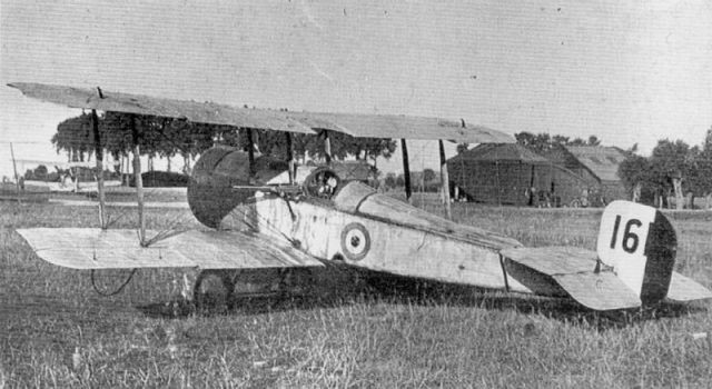
Scout C
An installation of cavalry carbine on a later production Scout C enabled Capt. Lanoe Hawker of 6 Sqn to shoot down one enemy aircraft in flames, drive another down and damage a third in quick succession on July 25, 1915. All three enemy aircraft were armed with machine-guns and Capt. Hawker was awarded the Victoria Cross.
The Scout D was a revised design which, completed in November 1915, had provision for a fixed synchronised 7.7mm Vickers gun. The Scout D was the first model for which armament was officially intended, though relatively few of these had the synchronised Vickers gun and the armament of others varied considerably. Some having a 7.7mm fixed Lewis gun firing straight ahead without synchronising equipment and others having a movable Lewis above the upper wing.
Scout D
A number of modifications were made at Bristol’s and the type was varied from the D-1 to D-5. Engines varied from the 80 hp Gnome and Le Rhone to the 100 hp Gnome Monosoupape, 110 hp Le Rhone, and 130 hp Clerget. Over 200 were built before the type was abandoned.
Of the 210 examples built, 80 went to the RN, of which 50 had 100hp Gnome Monosoupape engines and the remainder the 80hp Gnome. Most of those delivered to the RFC ultimately had the 80hp Le Rhone engines.
The Scout C and D had early limited use by the Australian 1 AFC in Egypt where Lt L.J. Wackett used one in experiments with a synchronised machine gun.
Altogether 236 Scouts were delivered to the RFC, and 137 to the RNAS.
Some RNAS machines had a Lewis gun mounted above the top wing. RFC Scout D’s had a Vickers gun above their front fuselage.
Scout C Engine: 80 hp Le Rhone, or Gnome, or 110 hp Clerget Wing span: 24 ft 7 in Wing area: 198 sq ft Length: 20 ft 8 in Height: 8 ft 6 in Fuel capacity: 16 Gal Endurance: 2 hr Service ceiling: 11,000 ft
Scout C Engine: 80 hp Clerget Wing span: 24 ft 7 in Wing area: 198 sq ft Length: 20 ft 8 in Height: 8 ft 6 in Empty weight: 750 lb MTOW: 1089 lb Fuel capacity: 16 Gal Max speed: 94 mph at SL Endurance: 2 hr Service ceiling: 11,000 ft
Scout D Engine: 1 x Gnome, 80hp. Wingspan: 24 ft 5 in Wing area: 198 sq.ft Length: 20 ft 7 in Height: 8 ft 6 in Empty weight: 757 lb Loaded weight: 1195 lb Max speed: 98 mph at SL Service ceiling: 15,500 ft ROC: 385 fpm to 6500 ft Endurance: 2 hr 30 min Seats: 1
Scout D Engine: 1 x Le Rhone 9, 80hp. Length: 20 ft 8 in (6.02m) Wingspan: 27.33ft (8.33m) Wing area: 18.39 sq.m / 197.95 sq ft Height: 8 ft 6 in (2.59m) Maximum Speed: 100mph (161kmh; 87kts) Rate-of-Climb: 540ft/min (165m/min) Service Ceiling: 13,999ft (4,267m) Armament: 1 x 7.7mm machine gun Crew: 1 Empty Weight: 761lbs (345kg) Maximum Take-Off Weight: 1,250lbs (567kg)
Scout D Engine: 1 x Gnome Monosoupape, 100hp Max speed: 104 mph at SL
After first buying a Zodiac biplane from France, which Bristol proposed to manufacture, they settled on a copy of the Farman III which was a better design and unlike the Zodiac could be made to fly successfully.
George Challenger, the company’s chief engineer at Filton, sfter seeing detailed drawings of the Farman III in Flight magazine, was pretty sure he could build a copy of the plane. A few weeks later, the first copy was constructed, using materials from the partially built Zodiac aeroplanes. The Farman copy is a tractor biplane having its upper and lower planes equal, directly superposed, and connected by 6 struts. The front struts are rigidly braced by cables; the rear ones free for warping. The fuselage is of quadrangular section. The chassis has four wheels.
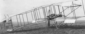
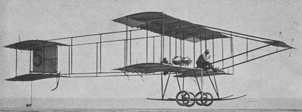
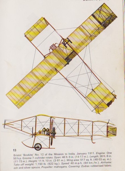
The Boxkite, as it was named, was first flown on 31 June 1910 by Maurice Edmond at the company’s flying school on Salisbury Plain with a 37kW Gregoire engine and in September 1910 made the first military flight when it was used in a reconnaissance role during Army manoeuvres on Salisbury Plain, which led to the delivery of the first military aircraft as an army co-operation machine in May 1911.
Farman, not surprisingly, sued the British and Colonial Aeroplane Company for patent infringement. However, White was able to show Farman that they had made significant alterations to Farman’s design to improve it… so Farman dropped the suit. The Bristol Boxkite was the first plane to be built in mass quantity, with four purchased by the British War Office in 1911, and others sold to Russia and Australia.
This plane was simply called the No. 7. Best guess is that the initial Zodiac was No. 1, with the five partially-constructed Zodiac‘s taking the numbering up to No. 6.
The first Boxkite, No. 7, used fitted with a Grégoire 50 horsepower motor, but even before its first test flight, they swapped it out for a same output Gnome motor.
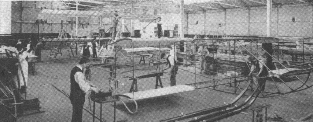
Boxkites under construction
For later trials, they put the Grégoire back in.
Boxkite No. 8 used an E.N.V. 50 horsepower motor.
Still, for almost all other aeroplanes, the company supplied the aeroplanes with the 50 horsepower Gnome rotary engine. Each motor was set just above the lower wing upon sturdy wooden beams, which, also held up the pilot and passenger seats up front.
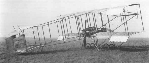
Although early Boxkite examples built had equal upper and lower wingspans, later ones had a longer upper wing (known as the Military version).
The No. 9, flown by pilot Robert Loraine in late September of 1910, was the first aeroplane to send a radio signal down to the ground, in Great Britain. Loraine, has his diary noted by the Oxford English Dictionary, as the first written example of the word “joystick” to describe aircraft stick controls.
Within a matter of months of the first flight the company was planning for expansion and mounting its first overseas sales drive. Missions were dispatched to Australia, India and other countries with good results. In November 1910 the first export order was placed by Russia for eight Boxkites and subsequently aircraft were also sold to Sweden, Spain, France, Italy, Turkey, Romania and Bulgaria.
The Boxkite has a rich history in the evolution of military aviation in Australia and was the first official military aircraft built in Australia that was used to train Australia’s military aviators.
A Bristol Boxkite was flown in Australia for the first time on 1 March 1914, when Lieutenant Eric Harrison took one into the air at Point Cook. The airfield was then the home of the Australian Flying Corps (AFC).
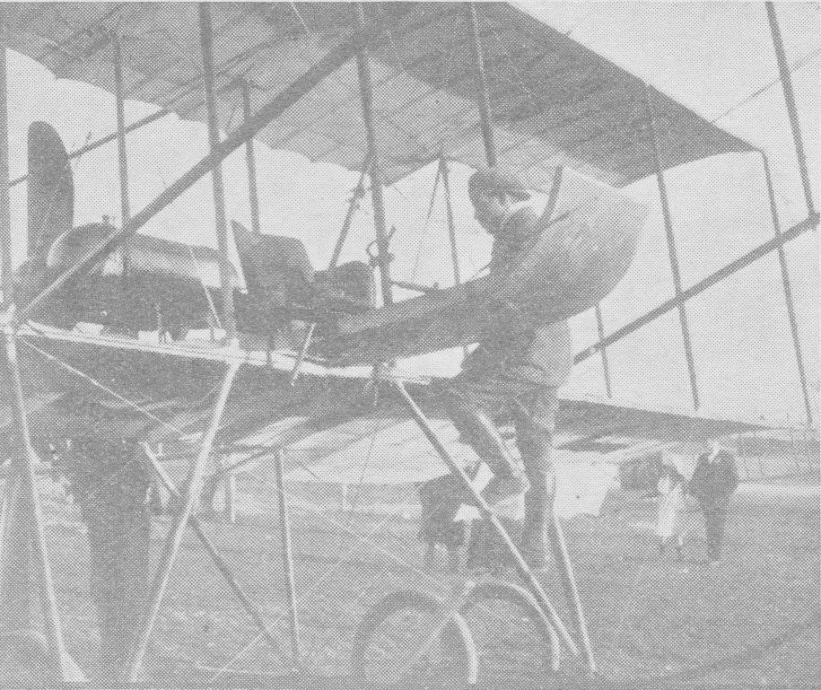
M. Jullerot in November 1911
On March 14, 1911, the British War Office ordered four Bristol Boxkites for its planned Air Battalion Royal Engineers—becoming the first production contract for military aircraft for Britain’s armed forces. A second order of four was made later that year, with them all pretty much being used as trainers for would-be pilots. When WWI broke out, four more were ordered by the British War Office, the last of which was written off in February of 1915, as obsolete. These aeroplanes were used as trainers at the Bristol flying schools at Brooklands and Larkhill, both of which were responsible for giving nearly 50 percent of British pilots their license before WWI.
By the time production of the Boxkite ceased in 1914, the British and Colonial Aeroplane Company had constructed 78 Bristol Boxkite aeroplanes in total, of which 60 were the so-called Military version, one (no. 44) was a Racer version, and one, No. 69, was a an unsuccessful Voisin variant.
Bristol Boxkite‘s No. 73-78 were built at Brislington by the Tramway Company, with all those before it manufactured at the Filton facility.
Three replica aircraft built for the movie Those Magnificent Men In Their Flying Machines. One is at the Bristol City Museum and Art Gallery, another at the Shuttleworth Collection at Bedfordshire, and the third is at the Museum of Australian Army Flying in Australia.
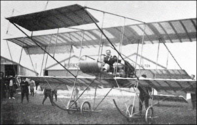
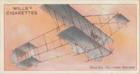
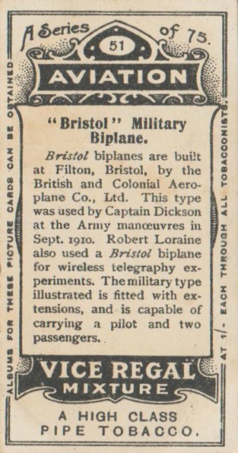
Wills’s Aviation Card #51 – “Bristol” Military Biplane.
Card #51 of 75, W.D.& H.O Wills, Aviation series 1911, Vice Regal Mixture issue
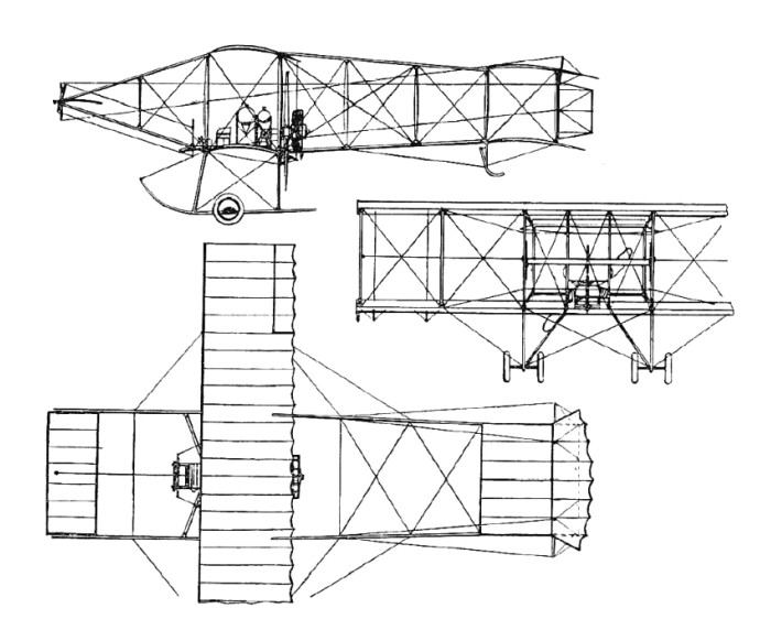
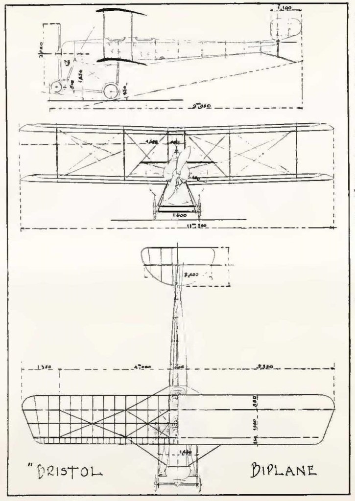
This card shows the Bristol Biplane (official name), though the Wills’s card calls it the Bristol Military Biplane, and the world seems to refer to it as the Bristol Boxkite.
Replica: RAAF Museum Bristol Boxkite Miles Bristol Boxkite
Bristol Boxkite Length: 38.386 ft / 11.7 m Height: 10.827 ft / 3.3 m Wingspan: 46.49 ft / 14.17 m Max take off weight: 1151.0 lb / 522.0 kg Empty weight: 363 kg / 800 lb Max. speed: 35 kts / 65 km/h Engine: Gnôme, 50 hp Crew: 2
Bristol Boxkite Engine: Gnôme, 80 hp Wingspan: 11.3 m Wing area: 40 sq. m Max. speed: 80 km/h
Boxkite Standard Engine: Gnôme, 50 hp Wingspan: 10.52 m / 34 ft 6 in Length: 11.73 m / 38 ft 6 in Height: 11 ft 10 in / 3.61 m Empty weight: 363 kg / 800 lb Wing area: 42.46 sq.m / 457.04 sq ft Max. speed: 64 km/h / 40 mph
Bristol Boxkite Military version Engine: 1 × Gnome Omega, 50 horsepower (37 kW) Wingspan: 14.17 meters (46 feet 6 inches) Wing area: 48.03 square meters (517.0 square feet) Length: 11.73 meters (38 feet 6 inches) Height: 3.61 meters (11 feet 0 inches) Empty weight: 408 kilograms (900 pounds) Maximum takeoff weight: 522 kilograms (1150 pounds) Maximum speed: 64 kilometers per hour (40 miles per hour) Wing loading: 10.9 kilograms per square meters (2.22 pounds per square foot) Power/mass: 70.9 watts per kilogram (0.043 horsepower per pound) Crew: 2