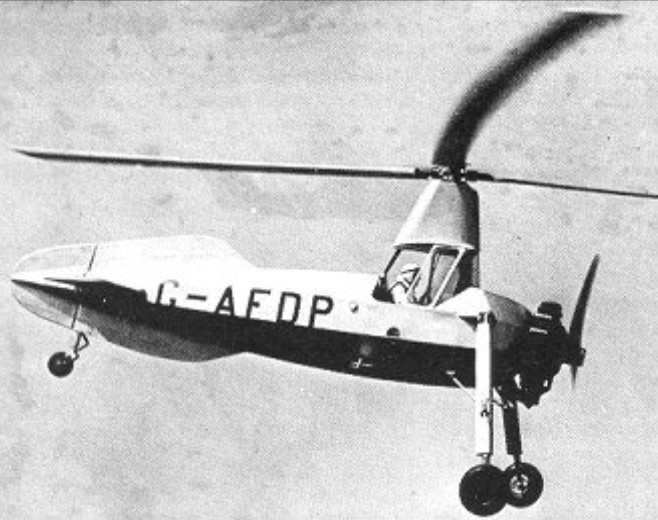
The C.40 autogiro was built under licence by British Aircraft Manufacturing Co. A small batch was produced for the Fleet Air Arm in 1938-39.
The C.40 autogiro was built under licence by British Aircraft Manufacturing Co. A small batch was produced for the Fleet Air Arm in 1938-39.
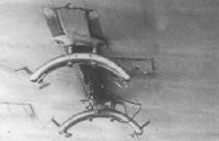
The Cierva C.30A marked a major step forward in rotorcraft development, being the first production autogiro in which the engine was geared directly to drive the rotor blades for take-off. The degree of direct control was increased still further by having the control column, which acted directly on the rotor, suspended from the pylon so that the rotor head could be tilted in any direction to produce the manoeuvre desired. The new-style control system was first installed in G-ABXP, a Cierva C.19 designated Mk.V with a 100hp Genet Major I engine. This was basically a C.19 Mk.IV modified to have a clutch and transmission shaft, a tilting rotor head and (later) a small, fixed tailplane.
Cierva C.30 Rota / Avro 671 Rota Article

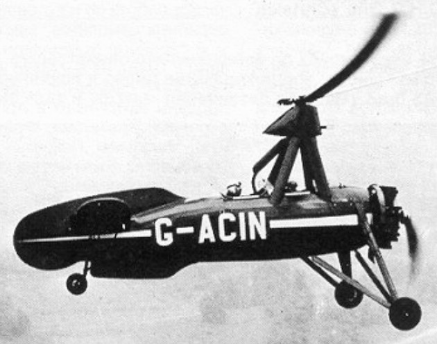
The prototype C.30 (G-ACFI) differed chiefly in having a tripod rotor pylon and dihedral on the tailplane tips; the fuselage was modified by Airwork from a standard Cierva C.19, and assembly was undertaken by National Flying Services at Hanworth, where G-ACFI made its maiden flight early in April 1933. Take-off run of the C.30 was about 30 yards (27.43m), while the landing was achieved in about 3 yards (2.74m) with the rotor blades autorotating. Another 1933 prototype was G-ACKA, the first C.30P, with 140hp Genet Major 1A, folding rotor blades and other improvements.
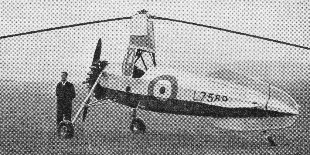
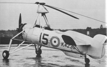
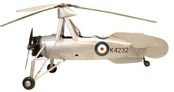
First customer for the production C.30A was the Royal Air Force, for whom the type was built by Avro and given the name Rota. One twin-float Sea Rota and ten standard Rotas with wheeled undercarriages were completed to Specification 16/35, and were delivered to the School of Army Co-operation at RAF Old Sarum from December 1934. By the outbreak of the Second World War they had been allocated for use by a highly secret unit engaged on ground radar calibration duties. One other military C.30A was K4775, a Civet Major-engined machine sent to the Royal Aircraft Establishment in 1935 for blade-flexing tests.
Nearly 150 were built under licence in the UK (Avro and Airwork), Germany (Focke-Wulf) and France (Lioré-et-Olivier). Airwork produced the C.30 and C. 30P, and Avro the C.30A and C.30P. The C.30A was built by A. V. Roe as the Avro Type 671 Rota for RAF and civil market.
The C-30A was the most widely produced Cierva autogyro design. Avro built the type under licence, as the Avro Type 671 Rota.
Avro production of C.30 types was in the region of seventy aircraft, three of which were C.30P’s. Thirty-seven C.30A’s appeared on the pre-war British civil register, and others were completed for customers in Europe, India, China, Australia and South Africa. In Britain the C.30A, like the C.19 before it, was used for traffic reporting duties at major sporting and similar events, and one aircraft (G-AGUT) was used for filming the 1936 F.A. Cup Final.
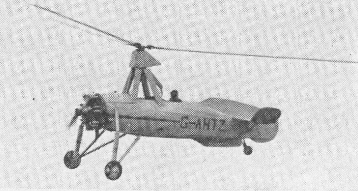
During 1933 the C.30 prototype, G-ACFI, was converted for jump-start trials with a modified rotor head, and in 1936 a perfected form of this was fitted to G-ACWF when it made the first genuine vertical take-off by an autogiro, by keeping the engine and rotor system engaged throughout the take-off sequence. This machine was, in effect, the prototype for the C.40, five of which were ordered for the R.A.F. as the Rota II to Specification 2/36. These were built by the British Aircraft Manufacturing Co., having side-by-side seats, wooden semi-monocoque fuselages and 175hp Salmson 9NG engines. Two of the original five Rota II’s were diverted to civilian customers, replacements being built in 1938-39. The R.A.F. C.40’s served with No.1448 Flight (later 529 Squadron). On the outbreak of World War 2 over a dozen civil C.30A’s were impressed for military service; these and the surviving Rota I’s were allocated singly to R.A.F. radar stations in the United Kingdom for calibration duties.
C.30A G-AHMJ was used by Fairey Aviation in the 1940’s for research that led to the Fairey Gyrodyne design. After retirement, it was moved to the rear of TS Broke, North Hyde Road, Southall, Middlesex, in the care of the Sea Cadet unit based there. In the early 1950’s it was aquired by the Shuttleworth Trust and restored in the 1970’s to it’s wartime camouflage scheme and serial number as an Avro Rota. It is now in the Fantacy of Flight Museum in Florida.
Concerning license manufacture of the type by Focke-Wutf, it is to be noted that Focke-Wulf did not obtain rights to produce the C 30 under license in 1933 as has claimed. License negotiations began in February 1935, initially with the “Hamburger Flugzeugbau G.m.b.H”, however these collapsed for financial reasons. Focke-Wulf entered the negotiations in July 1935. The start of license construction by Focke-Wulf was delayed on account of currency exchange difficulties until December 1935, when the exchange rate was guaranteed for 36 examples of the C 30.
Preliminary shipboard trials with the C 30 autogiro began on November 10, 1936 at E-Stelle See (Naval Test Station) Travemünde. The trials ended unsatisfactorily as a result of the type’s inadequate performance, its less than satisfactory handling characteristics in gusts and the poor view offered the pilot during deck landings on small platforms. Further development of the C 30 for military use was therefore abandoned.
C.30A
Engine: 1 x Armstrong Siddeley Civet 1, 140 hp
Main rotor diameter: 37 ft
Rotors: 3-blade
Fuselage Length: 19 ft. 8.5 in
Loaded weight: 1,900 lb Empty weight:
Max speed: 100 m.p.h
Ceiling: 8,000 ft
Range: 250 miles at 85 m.p.h
Seats: 2
C.30A
Engine: 1 x Armstrong Siddeley Genet Major IA, 104kW
Main rotor diameter: 11.28m
Length: 6.01m
Height: 3.38m
Max take-off weight: 816kg
Empty weight: 553kg
Max speed: 177km/h
Cruising speed: 153km/h
Range: 459km
Avro Rota Mk I.
Engine: Armstrong Siddeley Genet Major 1A, 140 hp
Length : 19.718 ft / 6.01 m
Rotor diameter: 41.995 ft / 12.8 m
Max take off weight: 1799.3 lb / 816.0 kg
Max. speed: 96 kt / 177 km/h
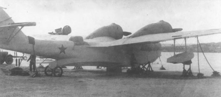
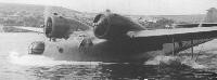
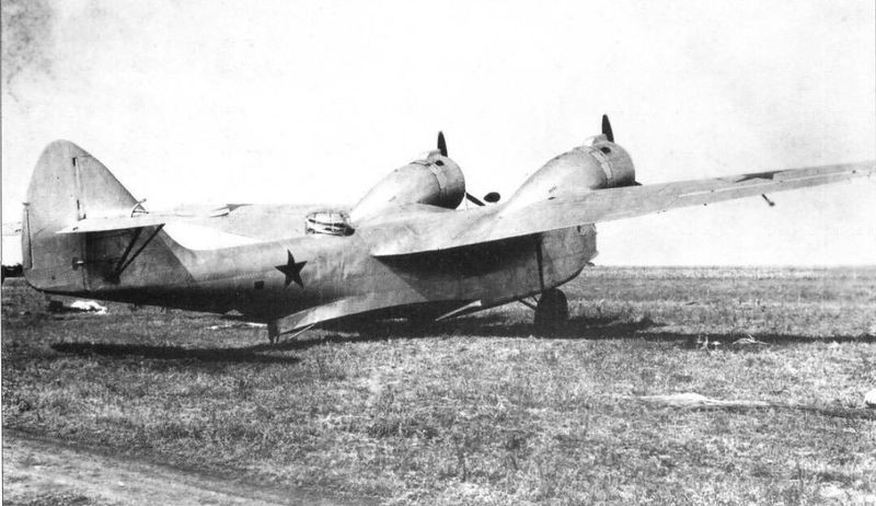
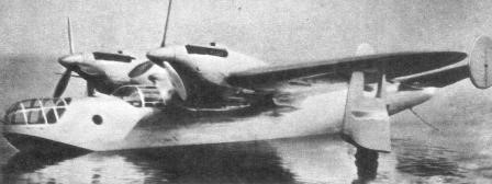
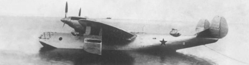
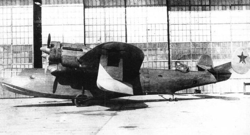
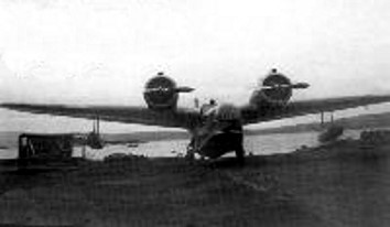
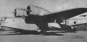
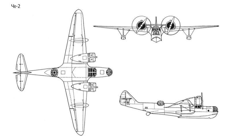
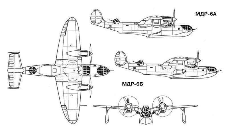
Shortly before the start of World War II, the USSR Naval Fleet received several types of flying boats, among which a model designed by a group of engineers under the general direction of IV Chetverikov stands out. This model, known as the MDR-6 after the acronym for Morskoi Dalni Razvietchik or Long -Range Naval Reconnaissance, distinguished itself by using a gull-wing configuration allowing the propellers to be moved away from the water without the need to increase the depth of the hull or resort to parasol wing schemes.
The MDR-6 or Che-2 (Четвериков МДР-6 (ЧЕ-2)) was designed from specifications issued in 1934 and reviewed by the mock-up approval commission on December 4, 1936.
It was produced in series as Che-2 between 1940 and 1941, 50 being built at Taganrog between 1939 and German invasion of Crimea in 1941. The short range and its designer’s attempt to obtain speeds similar to those of land-based bombers resulted in the appearance of a number of experimental models, which did not go into production due to the presence in the USSR of the Consolidated PBY Catalina, obtained under the Lend-Lease Act.
The MDR-6 was designed as an all-metal monoplane flying boat. The wing was shaped like a “gull” with a high set-up and cantilever configuration. Weight-compensating ailerons and hydraulically actuated flaps were installed on the trailing edge.
Construction was carried out by Factory No.45 in Sebastopol and the prototype was ready for its first flight in July 1937.
The M-25Ye engines used had been experimentally manufactured by Factory No.19, Perm, under the direction of Arkadi Dmitrievich Shvetsov, and used on a trial basis in the crashed ARK-3. The use of these experimental engines was considered as a temporary measure intended to speed up the development of the model tests.
The M-62 was considered more suitable as it featured similar shapes and the same mounting points as the Shvetsov M-25, while offering more take-off power with minimal weight gain. Improved performance, increased rate of climb, and fuel economy were expected with the M-62 engine.
The centroplane was inserted at an angle against the body of the flying boat, ending in the form of a fairing. At the other end of the midplane, the engines were installed high above the wing turning point, in order to move the propellers as far out of the water as possible. The wing consoles were trapezoidal in plan with elliptical ends. The dimensions of the wing changed with the development of the model. The first prototype featured fixed stabilization floats, maintaining this configuration in the production copies, but later experimental models introduced retraction systems seeking to improve performance.
The hull had a double groove and a pronounced keel. The first redient had a transverse shape and the second sharp. The entire cross section of the flying boat showed curved lines. The model’s nose was very short, necessitating the use of splash deflectors. After the first tests it became necessary to make some modifications to the reentrants and the bow area. Behind the second redient a rudder was installed. These changes were implemented at Factory No.45 in Sebastopol and resulted in increased stability in the water and decreased splashing during takeoff and landing operations.
The entire aircraft was covered with metal sheets with thicknesses between 0.8 and 2 mm, except for the ailerons, rudders, the rear part of the wings and, in some models, the keel.
The tail was of a conventional monoplane type with the planes set high on the keel. After the first flights, mounting brackets for the tailplanes with trimmers and weight compensators on the rudders were introduced. The rigid engine control system was replaced by cables.
The fixing of the motors to the wing was carried out by means of supports installed directly on the wing structure, without using independent benches. The wing included in its structure 10 fuel tanks and two oil tanks, with capacities of 2,160 and 240 liters respectively. The M-25Ye engines with a nominal power of 710 hp at 5,400 m and a weight of 453 kg, moved variable-pitch VISh-6 propellers with a diameter of 2.8 meters.
The crew of the MDR-6 was made up of four people: two pilots, a navigator and a gunner-radio operator, located in three segments of the hull separated by watertight walls. An RSRM radio station and an AFA-13 camera were located in the radio operator’s cabin. In the cockpit of the pilots an RSVS radio. The internal communication system included a SPU-3 intercom, pneumatic mail system, a light signal system with three lamps, and the RSVS radio station. For radio transmissions when the flying boat was on the water, a retractable mast was designed for the antenna.
The armament was distributed in three firing points. In the nose was located a NU-DB-3 installation with a 7.62 mm ShKAS machine gun and a KPT-5 sight. The ammunition box with 1000 shots was located on the right side. At the bottom of the hull was a mat on which the shooter sat. In the upper part of the turret there was a slot to place the machine gun firing at an upward angle. When the machine gun was not installed this opening was sealed by three small armored shields.
The intermediate station featured an SU-DB-3 type turret with a 7.62mm ShKAS machine gun with 2000 rounds. Steps were installed on the hull floor to facilitate operation from this position. The operator of this weapon had a retractable seat. In the rotating ring of the turret the fixation of an oxygen system was envisaged.
The rear firing point was shaped like a hatch and was similar to the one used in the lower area of the rear fuselage on the Ilyushin DB-3 bomber. It was equipped with a 7.62mm ShKAS machine gun. The ammunition box with 1000 shots was placed on a designed surface on the right side. During the transfer, the machine gun was kept in a vertical position fixed to the right side of the flying boat. A safety belt for the shooter was located on the left side lining.
The maximum bomb capacity of the MDR-6 was 1,200 kg. The compositions varied and could be one of the following:
12 FAB-100 or FAB-50;
4 FAB-250 or BRAB-220;
2 FAB-200.
The FAB-250 and FAB-500 heavy bombs were attached to DER-19 external mounts located in pairs under the wings. The fixation of these bombs was carried out by means of a BL-3 rope system located on the surfaces of the plane. The FAB-100 bombs were located in horizontal cassettes fixed to DER-31M supports. These cassettes were located under the wings inside the locations of the DER-19 mounts and the attachment of the bombs to them was done manually. Two DER-32 brackets for flares were also installed. The launch systems were linked to the supports by a cable system that included emergency wiring. The bombing system used an OPB-2 targeting system.
During the development of the tests, the possibility of using the UJAB-500 universal chemical weapons container built by Factory No.145 of the NKAP was evaluated in the MDR-6. With dimensions similar to those of a FAB-500 bomb this container could be located under the wing.
The first MDR-6-2M-25Ye was built as a long-range naval reconnaissance flying boat and light bomber and was generally a military development of the ARK-3/2 polar scout.
The second stage of state tests of the experimental prototype MDR-6 took place between July 2 and 22, 1939 in Sevastopol ( in the waters of Gollandia Bay and in Lake Donuzlav).
The test brigade was composed of:
Chief Engineer: Military Engineer 2nd Rank NI Chernyshiov;
Assistant Chief Engineer: Military Engineer 3rd Rank Kolchinsky
Lead Pilot: Major Slobodchikov;
Chief of Armament Engineers: Major Tyutlyayev;
Assistant to the Chief of Armament Engineers: Military Technician 1st Rank Borobiov;
Chief Engineer at VMG: Third Rank Military Engineer Bielkind;
Navigator: Senior Lieutenant Oljovikov;
Second Pilot: Senior Lieutenant Yefimienko;
Shipboard Technician: Military Technician 1st Rank Salomatov;
The program of the tests was approved by the head of the AU RKVMF division commander Zhavoronkov and the military commissar of the AU RKVMF brigade commissar Alexeyev. The test results report was signed by the head of the VVS of the Black Sea Fleet Brigade Commander Rusakov and the military commissar of the LII ARKVMF Battalion Commissar Mochalov.
The tests comprised 14 runs and 39 flights. Of these last 13 were made in a circle, 10 looking for behaviour at height and 16 normal flights, totalling 34 hours in the air. On land they accumulated another 5 hours. Of the total flights, 30 were carried out with payloads in exploration and bomber variants. Operations were carried out with wind speeds of up to 8 meters per second and waves of up to 0.5 meters. The maximum recorded overloads reached the value of 1.78 g.
During the flights a maximum speed of 405 km/h was reached with a ceiling of 5835 meters. No vibrations were seen in any of the tests. Bomb load turn tests were performed on cassettes of 12 FAB-100s for a flight weight of 5,900 kg.
According to the resulting documents, the tests of the MDR-6-2M-25Ye in relation to overloads, seaworthiness, take-off and landing characteristics and flutter resistance were considered positive.
The report recorded:
“The plane was towed by a boat to the exit of the cove and the engines were started there. Thanks to the optimal location of the engines and the presence of an effective rudder, the MDR-6-2M-25Ye is very maneuverable in the waves. The race to the start can be done with a single motor at values between 500 and 1200 revolutions per minute.
The aircraft safely maintains the course, does not show any tendency to drift during takeoff and navigates stable on the edge. After takeoff, the machine behaves normally and when it reaches 150 km/h speed, it smoothly searches for the angle of climb. The loads on the stick are decreased by the elevator trimmers.
In horizontal flight, the plane presents a good balance in all speeds, positions and weights, maintaining centering between 28% and 34% of the length. The longitudinal and transverse stabilities are good if the tendency to bite on the wing is appreciated. In case of problems with the engines, it is easily passed to the glide regime. Upon failure of an engine, the airplane at normal flying weight can continue to fly after removing the load from the rudder trimmer and giving full throttle to the operating engine.
The aircraft responds promptly to the rudder with a normal stick load in all flight regimes and with loads up to 7,000 kg can be easily balanced using the trimmers. The effectiveness of the rudders in takeoff, flight and landing can be considered sufficient.
Recovery after a turn is easy with the rudder, without the need to vary the work rite of the motors or use the trimmers. The optimum turn is made with a bank of 60 degrees at 210 km/h. The turn is stable, without tendencies to dive or jump.
The entry and exit of the spirals is done with the help of the rudder without the need for trimmers and motors. In the spiral the plane is stable. The optimal spiral is obtained at 180 km/h with an angle of 45 degrees.
Flutter was not observed in any of the flight regimes.
Switching from any flight regime to glide is easily done with the rudder. The plane during the glide is stable in the longitudinal and transverse axis. Optimum glide speed with flaps extended is 150 – 160 km/h on instruments (depending on load).
Landing depends on the position of the aerodynamic brakes. With them extended the landing is rougher, without them the glide angle is lower and the plane descends smoothly (as with the MBR-2). Landing takes place at speeds of 110 – 115 km/h and the run lasts about 18 – 20 seconds, depending on the load. In this operation no trends of deviation are appreciated.
The aircraft normally lands in crosswinds of 6 – 8 m/s and at angles of 65 – 70º to the wind direction. After landing the hydrocanoe can sail to the entrance of the bay or turn off the engines and wait to be towed from the bow hooks by a speedboat.
The aircraft is comfortable for pilot training due to its side-by-side seating arrangement, duplication of controls and instruments, and visibility from either seat. The piloting technique is simple and accessible to a pilot of medium qualification.”
Despite these evaluations, some negative aspects were also pointed out, among which the following stood out:
Difficult working conditions of the propellers in airplane overload conditions, which led to their replacement every 40-45 flight hours;
Failure of the oil cooling system;
The need to modify the fuel supply system in a way that would allow the fuel tanks to be replaced without having to disassemble the wing;
The fuel capacity, acceptable for bombing missions, was insufficient for reconnaissance tasks;
Need to improve engine hoods;
Poor visibility from the navigator’s cabin. The small skylights on the railings did not guarantee the necessary visibility (the visual sector only admitted 60 – 70º);
The cockpit and forward position received water during runs and take off, which increased depending on the strength of the wind;
The anchor was located under the pilot’s seat on the right, so the navigator had difficult access to it
The navigator’s seat was in a comfortable position but needed modifications because in order to observe through the turret windows it was necessary to stand up;
The SPU-3 intercom system performed poorly during testing and the pneumatic mail system proved to be ineffective. The light signals, on the other hand, worked very well;
The AFA-13 photographic apparatus was located with all the rest of the equipment in the shooter-radio operator’s cabin, which made its use difficult;
In the navigator’s cabin, the lack of equipment necessary for his work was felt: visual orientation when taking the course could only be done by looking through the turret screens, the liaison with the pilot in these operations was only in writing, location measurements had to be made using the OPB-2 collimator, radio equipment for navigation was lacking; orientation by stars through the upper hatch could hardly be carried out by the force of the wind in the absence of a transparent cover.
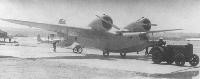
One of the collateral tasks of the military tests was the study of the conservation conditions of the flying boat. The MDR-6 could be kept in hangars and in the open air. Exit from the hangar and transfer to the water was carried out with the help of a JTZ (ХТЗ) tractor. In case of lacking the tractor this operation could be done by eight people.
The entry and exit of the water was carried out by three people with the help of a pair of divers. The time of putting in the water counting on the removal of the transfer wheels took 3 – 5 minutes. This process required a JTZ tractor, a PPK-35 crane, a tail lift jack, a Yaroslaviets boat, a BZ-35 (БЗ-35) tanker, an APV-4N (АПВ-4Н) engine heater, a thermos of water – oil VMT-35 (ВМТ-35). For winter operations, a GAZ-AA (ГАЗ-АА) starting system and a ChTZ (ЧТЗ) tractor for ski operations were added. Extraction from the water took 5-7 minutes.
Refueling time from the BZ-35 tanker with two hoses took about 10 minutes and oil about 30 minutes (due to the narrowness of the oil intake).
Access to the engines was highlighted as a positive, but it was pointed out that there were few hatches for the maintenance of the systems and aggregates and many maintenance actions required the disassembly of the hoods, which considerably increased the time of interventions;
In general, the assessment of these conditions showed that the MDR-6 did not need special conditions for its operation and could operate from the same bases used for the MBR-2 flying boats.
In relation to the armament system, it was found that it was difficult to guarantee hitting the targets due to the lack of windows in the bow, under the turret. The target was lost under the plane and the launch of the bombs could be sensed, using the ESBR-3 and AS-5 systems for their release.
The DER-19 supports proved to be very vulnerable to weather conditions. At temperatures below 20-25 degrees, the number of failures tended to increase and they were quite sensitive to the action of saltpeter, which required constant maintenance.
The forward navigator’s turret easily received seawater during overwater operations, necessitating careful cleaning of this area after each flight to prevent corrosion of the turret and armament. The hatch type station located in the lower part of the tail also received a lot of water, which affected the operation of the machine gun.
During the weapons tests from the UN turret, it was verified that the shot was effective in any position and at any height, differing only in the speed of the maneuver. The installation guaranteed all the permissible angles of the shot. Visibility was allowed by the armor screen at all angles of turret operation. It was noted that the turret lacked limiters so there was the possibility of firing the engines during combat. The weapon’s feeding system did not generate any signal. The link between the navigator’s cabin and the turret was also considered without difficulties.
The location of the machine gun on the right rail and vertical position when not in use was valued as very positive. In that location it did not affect the work of the navigator or the pilots.
By directing the dorsal “SET” turret (from the acronym Samoliotnaya Elektrofitsirovannaya Turel or Electrified Aviation Turret) backwards or forwards at angles of 30 – 40º the sides of the hull limited the aiming angle. The oxygen system could be fixed to the mobile part of the ring in the gunner’s turret, but its short hose did not allow moving from the dorsal to the tail turret without loading the ball, which made the shot more complex. The instrument board had a correct position and even serving the machine gun you could turn your head and see the indicators.
The feeding system of the machine gun in the rear turret type “LU” did not present an acceptable termination and the bushings collided when falling with the control cables of the maritime rudder. Water accumulated in the hatch that bathed the gunner and the armament during opening. The cockpit was tight and uncomfortable to shoot lying down. The mounting base of the machine gun was not strong enough, although its assembly and disassembly were easy.
The variants of bomb loads were tested on land and in the water. In the latter case, a special raft designed by Factory No.48 was used, which in practice proved to be ineffective. Above the water, the FAB-500 pumps were raised by means of a pulley mechanism operated by one person. The ground operation was carried out by three men from a wheelbarrow. The average installation time for four FAB-250 bombs on the ground was 40 – 50 minutes. The installation of 12 FAB-100 bombs was carried out by 5 people in 45 – 50 minutes, including the installation of the triggers.
The tests showed that during takeoff and landing operations, the pumps and supports suffered constant splashes of water, especially the first three located closer to the sides. The DER-19 supports, operated from the ESBR-3 and AS-5, worked without problems. The use of the OPB-2 aiming system was comfortable. DER-32 media failed the low temperature test.
When placing the pumps in the cassettes, it was possible to verify that due to lack of rigidity, the pumps located near the ends and the center began to vibrate during takeoff and landing operations. The DER-31 mounts worked without a problem.
The actual capacity of large caliber bombs was 1000 kg in configuration of 4 FAB-250 or two FAB-500. It was considered that the requirement of the evaluation commission of the model was not met, which requested a maximum load of 1500 kg (six FAB-250).
The pulley system for installing the heavy gauge pumps was approved for installation on production examples after some minor modifications. It was decided to develop a new raft in order to be able to install pumps in the water in any weather conditions.
On July 20, 1939, a test combat of the MDR-6-2M-25Ye was held with a group of Polikarpov I-16 fighters, which lasted one hour and took place at altitudes of 1,500 – 2,000 meters. All the planes were equipped with SLP photo-machine guns in order to define the defensive capacity of the flying boat and the maneuverability of the armament.
The MDR-6-2M-25Ye would fly along the Donuzlav Lake – Kamenolomnya airfield route at an altitude of 3,000 meters. The fighters should take off from their airfield when the MDR-6 descended to 1000 meters. Fighter attacks would be made from heights of 3,000-3,500 meters.
The crew of the MDR-6 consisted of senior tester pilot Slovodchikov, navigator and bow gunner senior lieutenant Olkhvikov, second-rank engineer Chernishov as second pilot, senior weapons engineer Tyutlyayev as dorsal gunner in the “SET” turret. and Military Technician 1st Rank Borobiov as Gunner of the “LU” Tail Station.
The crew of the I-16 fighters consisted of Regimental Commander Major Pavlov (leader) and Squadron Commander Captain Shubikov and Senior Lieutenant Yashkin as points.
During the fighter attacks the flying boat managed to maintain a speed of 250 – 275 km/h. The results of the tests showed that the MDR-6 was vulnerable to attack by the fighters and that the success of the reconnaissance mission would be based on avoiding combat with the enemy fighters, arriving unexpectedly at the objectives and remaining there for the least amount of time. possible time.
It was determined that the defense of the rear hemisphere was insufficient, especially in the tail area, where “dead zones” were formed that were not covered by machine gun fire. The absence of side hatches considerably reduced the effectiveness of the lower “LU” station. It was shown that in practice a single crew member was unable to defend the “SET” and “LU” stations at the same time. At high altitudes, changing from one position to another was difficult and quickly tiring. On the other hand, if the shooter-radista was wounded, the entire rear hemisphere was left unprotected.
In the report of the results of the combat tests it was considered, despite the deficiencies indicated, that the defensive capacity of the MDR-6 was acceptable for this type of aircraft. The MDR-6 with M-25Ye engines managed to pass combat tests.
As a result of state and combat tests the MDR-6-2M-25Ye was approved for serial production at Factory No.45 and entered service with the RKVMF.
To create the base model for production it was proposed to Chetverikov to prepare the model with a set of modifications and resubmit it for state tests. This upgraded model was to feature two Shvietsov M-62 engines with in-flight variable pitch propellers, ability to mount wheels or skis, upgraded bomb cassette system, modifications to defensive system and chemical weaponry, revised oil cooling system, protection of fuel tanks against impacts and increase in capacity to 2200 kg.
It was projected to locate in one of the series copies to be produced in 1940 some machine gun installations in the motor gondolas, in order to increase the defensive capacity.
The second prototype with Shvietsov M-63 engines was selected as the base model for the series and received the factory designation “H”. This specimen had a slightly larger wingspan and the stabilization floats were braced by tension straps. The tailplanes featured V-shaped bracing supports.
This prototype presented the possibility of installing wheels without the need to lift it, which could be replaced in winter by skis. The takeoff weight reached 5,600 kg and 6,450 kg in the supercharged version.
This example was successfully tested between September 21 and October 4, 1940 by the test pilot Shevnin, showing a speed of 338 km/h at sea level and a calculated technical range of 2,650 km. Performance was initially considered satisfactory, but claims were soon made to bring it closer to that of the Ilyushin DB-3 bomber, forcing Chetverikov to work through various development versions.
Factory No.31 in Taganrog was initially selected to carry out mass production of the model, which began work in September 1940. At the beginning of 1941 Chetverikov was appointed chief builder of Factory No.30, located in Savielov, with the task of producing 100 examples of the model.
Production of the Che-2 closed in 1941. Different sources assert that a total of between 20 and 50 copies of the Che-2 (name of the MDR-6 from 1941 in honor of its designer) were produced, but more recent studies establish that production in only 17 copies, of which 13 were finished in Taganrog and only 4 in Factory No.30.
Most production examples were delivered in a version sometimes referenced as the MDR-6A, with 1,100 hp Shvietsov M-63 engines, although some were completed with M-62s.
The Che-2 featured a composition quite similar to the MDR-6-2M-25Ye in relation to the location of its firing points. The defensive armament was generally made up of three 7.62 mm machine guns, but in some units it was replaced by one 12.7 mm machine gun and two 7.62 machine guns. The maximum bomb capacity reached 1200 kg, but generally the Che-2 flew with a load of only 400 kg. The last examples produced featured a modified bow turret and an MV-5 turret in the dorsal position, as well as the use of unguided rockets in underwing installations.
Despite its large dimensions, the airframe was quite light. The empty weight did not exceed 4100 kg and the flight weight 6700 kg. In overloaded version the aircraft reached 7200 kg. Its streamlined shapes allowed the MDR-6 to display good flight characteristics and excellent seaworthiness. The maximum speed reached 360 km/h and the ceiling 9000 meters.
Chetverikov set out to raise the flight characteristics of the MDR-6 with the aim of bringing them as close as possible to those of the Ilyushin DB-3 serial bomber and along the way he set out to develop a set of versions that were known as “A” and later “B” in variants 1 to 5.
In some literature the MDR-6B versions are known under the name Che-6. Both versions differed significantly from the production prototype, also known as the “H”. Visually, the redesign of the bow and the introduction of a bi-derived tail with a notable positive dihedral stood out. Another noteworthy aspect was the substitution of the radial motors for other linear V-shaped ones with water cooling.
Version “A” appeared in 1940 and was characterized by the introduction of inline motors M-105 of 1050 hp of power and a reduction in wingspan to improve speed. In some sources this model has been called the MDR-6A/2 to differentiate it from the standard MDR-6A (Che-2). The underwing floats were modified, presenting a characteristic shape that allowed them to retract until they were located between the wing spars.
The bow turret and cockpit glazing were modified, obtaining a much more streamlined shape and increased glazing. The rear turret was moved to the rear area and the tail was modified with independent sharp dihedral planes with drifts and stabilizer tip terminal rudders.
The hull kept the same thickness of 1.9 meters and the construction was basically the same with a semi-monocoque structure. The internal skeleton was built on the basis of pressed and shaped beams. The bow featured a new design in which the rotating turret had been removed.
The projection of the model “A” began in the fall of 1939. The specimen was produced in 1940 and between that year and the following year it passed the factory tests, which were carried out by the pilot D. Slavodchikov, but unfortunately it was destroyed in an accident that occurred near Uglich, during the transfer flight to the construction site. of state tests.
The MDR-6B or B1 was a modification of the original MDR-6 and like the “A” version used a 1050 hp M-105 linear water-cooled powerplant and shortened wing consoles for higher speed. The stabilization floats in this version were enlarged so that they could not be inserted completely inside the wing plane.
The wing featured all-metal construction with two spars made from 60x60x6 mm steel profiles. The coating up to the second spar was 2 mm thick in the center plane and at the base of the consoles and 0.8 mm thick towards the wingtip. The posterior area presented tissue coverage.
The M-105 engines had less frontal area than the M-63, even despite the need to install radiators for the water, which were located under the midplane, behind the second spar.
The flying boat featured very clean lines, making it one of the most visually pleasing models built in the USSR. The speed reached 454 km/h at an altitude of 6000 meters. The armament remained similar to that of the initial model and consisted of three ShKAS machine guns and a load of 1000 kg of bombs.
The MDR-6B1 saw the light of day in the spring of 1941 and passed factory tests without difficulty. On October 26 of that year, the flying boat was flown to the site where the acceptance or state tests were to be carried out. The B-1 arrived without problems but the tests could not be concluded due to the presence of problems with the power plant. Problems were also detected with the retraction system for the stabilizing floats, which were not fully inserted into the wing due to a defect in the design of the arms of the collection mechanism. The new engines brought the propellers closer to the water as a result. In this case, not only the splashes, but even the waves, reached the rotating blades.
The model was considered to be prospective, but it called for modifications in a series of aspects and improvements to the power plant. It was also requested to take measures to increase the scope.
The MDR-6B2 was a development of the MDR-6B1 and generally repeated its construction and dimensions. This model appeared in 1943 with the same M-105 engine as the previous model but incorporated radiators inserted into the wing leading edge using lattice-type grilles in an implementation similar to that used on the Tupolev SB bomber. In this model the floats were presented with increased volume and when they retracted they were not completely inserted into the wing.
The hull had the same dimensions, but the increased weight had raised the waterline. The seaworthiness was slightly affected and despite the installation of splash deflectors, taking off in waves was quite difficult.
During tests this model showed similar performance to the MDR-6A but the range remained insufficient.
The MDR-6B3 had the same dimensions and wing construction as the previous B-series models. Its construction was developed in 1943 in parallel with the B2 and the only noticeable difference at first glance was the use of an M-105PF 1150 engine. hp (variant made from 1942; changes introduced allowed a significant increase in power output at the expense of performance at higher altitudes) on newly designed power pods and slightly modified stabilization floats. Another difference was the installation of a more powerful defensive armament: two UB machine guns were located in the tail area and the crew was increased to 5 people.
The maximum weight of this variant grew, reaching 7,200 kg in normal version and 8,200 kg in supercharged configuration. Internal fuel capacity was 1,100 kg.
Despite impressive performance improvements over the standard Che-2, this model was not liked by the Soviet Navy as a result of its inadequate hydrodynamic performance in heavy seas.
To achieve the range of 3000 km requested in the specifications, the MDR-6B4 version was created, which saw the light in 1944 and for the first time introduced important modifications aimed at improving the seaworthy characteristics and preventing the propellers from coming into contact with seawater.
The hull of the flying boat was thickened, reaching 2.2 meters instead of 1.9 meters in the initial versions and the overall height was increased by 0.4 meters with elevation of the tail area and empennage. The rear tooth was displaced backwards. As a distinctive aspect, the empennage surface was increased by adding a third keel in the central position.
The stabilization floats became fixed, located on braced supports. It became necessary to abandon its retraction because when increasing the height of the flying boat it was necessary to lengthen the supports of the floats and they could no longer be housed in their old position.
As powerplant this model kept the 1150 hp M-105PF with radiators inserted in the leading edge of the wing. Fuel capacity was increased to 2,150 kg. The total weight of the new model was increased to 10 tons.
The crew of the B4 was five people. Defensive points were improved, increasing coverage angles. Defensive armament included three UB machine guns, maintaining the same 1,000 kg bomb load of earlier models.
The tests of the model (factory and state) were carried out between July 4 and October 18 at the test base of Factory No.458. IM Sujomlin was selected as test pilot and flights were made with a total duration of 8 hours and 36 minutes. On October 30, 1945, the aircraft made a flight along the Taganrog – Stalingrad – Astrakhan – Baku route as part of the joint test program.
Deliveries of Consolidated PBY Catalina flying boats under the Lend-Lease law greatly harmed the possibility of production of the MDR-6B-4.
The MDR-6B5 was the most advanced model of the experimental series and its production was not approved due to the end of the war and the concept that large flying boats were no longer necessary.
The MDR-6B5 was the last experimental model of this flying boat and was a development of the B4 with a new 1700 hp VK-107 engine. The radiators featured lattices at the outlets and were located under the wing, between the spars. The propellers were metallic with variable pitch and three blades.
The hull was similar to that of the MDR-6B4, but included a 0.5 meter lengthening of the nose obtained by moving the cockpit forward with respect to the wing leading edge. The midplane was enlarged and the consoles remained similar to those of the B4. The tail unit increased its area, but the central empennage disappeared.
Armament was enhanced with the installation of three 20mm B-20 cannons. One cannon was located in a fixed installation in the nose and held 200 shells. Two other guns were installed in the “SEB” turret (from Samoliotnaya Elektrofitsirovannaya Bashnya or Aviation Electrified Turret) with 300 rounds. Bomb capacity remained similar to previous models, being able to include four FAB-250 monsters or two FAB-500s.
The weight of the armament reached 125 kg, air navigation instrumentation – 69 kg, electrical and communications equipment – 172 kg, other equipment and materials – 542 kg. The constructive weight of the aircraft was 235 kg, the engines weighed 3067 kg. The empty weight of the B5 was 5610 kg, almost the takeoff weight of the Che-2 and its flight weight exceeded 10 tons.
The prototype of this version was completed by the summer of 1945 and successfully passed factory tests. During the tests, the excellent maneuverability of the model and its good seaworthiness were highlighted. With the approaching end of the war the plane was not handed over to state tests.
The first MDR-6 examples (by that time Che-2) were framed in units of the VVS of the Baltic Fleet at the end of 1940. From July 1941 two squadrons with these aircraft operated from Tallinn, carrying out reconnaissance tasks in the central and southern regions of the Baltic Sea, sometimes reaching the German coast.
In August 1941 the Che-2s participated in securing the bombing raids on Berlin carried out by DB-3F bombers from Saariema Island, being used as floating signallers on the water.
In September 1941 the Baltic specimens were transferred to the Northern Fleet where they were used primarily for distant reconnaissance. The Che-2s carried out reconnaissance on the icy waters looking for enemy ships. Most of these specimens had been lost by the end of 1941, but one specimen survived until the end of the war.
In the Black Sea the Che-2 operated from the summer of 1942. From Gelendzhik and then from Poti, conducting reconnaissance on German supply routes. In November-December these planes participated as cover for the naval group led by the cruiser “Voroshilov”. From 1943 the Che-2s were used mainly in the search for submarines. On August 4 of that year a Che-2 located a German submarine near Sukhumi, hitting it with an unguided rocket. The submarine was later sunk using depth charges. Later the Che-2 carried out some other attacks of this type in the black sea the model was used until the end of the war.
In the Pacific Ocean the model was used from 1941. Some copies were used in operations against Japan in August 1945.
The last examples of the Che-2 were withdrawn from active service in 1946.
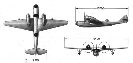
MDR-6-2M-25Ye
Powerplant: Two 710 hp M-25Ye experimental radial engines
Wingspan: 22.00m
Wing area: 58.90 m²
Length: 15.80m
Height: 3.99m
Empty weight. 4087kg
Normal takeoff weight: 6450 kg
Maximum takeoff weight: 7000 kg
Top speed: 338km/h
Cruising speed: 286km/h
Practical range: 2650 km
Climb speed: 286m/min
Practical ceiling: 8500 m
Accommodation: 4 crew members (two pilots, navigator and gunner-radio op)
Armament: Three ShKAS machine guns
Bombload: 1000 kg
Che-2 / MDR-6A
Powerplant: Two 1,110 hp Shvietsov M-63 experimental radial engines
Wingspan: 21.00m
Wing area: 59.40 m²
Length: 15.73m
Height: 4.30m
Empty weight. 4100kg
Normal takeoff weight: 6700 kg
Maximum takeoff weight: 7200 kg
Maximum speed at 4000 meters: 360 km/h
Cruising speed: 309km/h
Practical range: 2650 km
Ascent speed: 35m/min
Climb to 5000 m: 12 minutes
Practical ceiling: 9000 m
Accommodation: 4-5 crew (two pilots, navigator, gunner-radio op and tail gunner)
Armament: One UB machine gun and two ShKAS
Bombload: 1000 kg
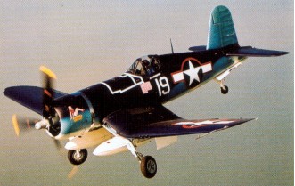
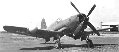
A design team headed by Rex Biesel and lgor Sikorsky set out to tackle a February 1938 US Navy requirement for a single seat carrier borne fighter; the challenge being to build the smallest possible fighter around the most powerful air cooled engine then under development.
Such a huge propeller was required for the world’s first 2000 horse power engine a Pratt and Whitney 18 cylinder two row Double Wasp radial that the team followed Junker’s lead in using an inverted gull wing to provide sufficient ground clearance for the 4.1 metre (13 feet 4 inch) three bladed Hamilton constant speed propeller.
The wing design also enabled the use of short and strong oleo legs capable of withstanding operational carrier landings and, as an added benefit, the wings folded from the lowest part of the wing to provide a low overall height when the wings were in folded configuration. On retraction the gear rotates through 89 degrees and then folds backwards into the wing. As the weight is taken off the oleos the legs are prevented from extending by cables. The distinctive gull wing shape was used to allow the very large diameter propeller to be used and still keep a relatively short strong undercarriage for aircraft carrier operations.
In 1938 the Navy became involved in three new fighter projects the Grumman XF5F 1 and similar USAAF XP 50, the Bell XF1 1 and the Vought XF4U 1 (V-166A). The long term intention was to bolster the Navy’s sagging carrier forces whose squadrons flew the Grumman F3F 2 biplane fighter harking back to the mid1930s.
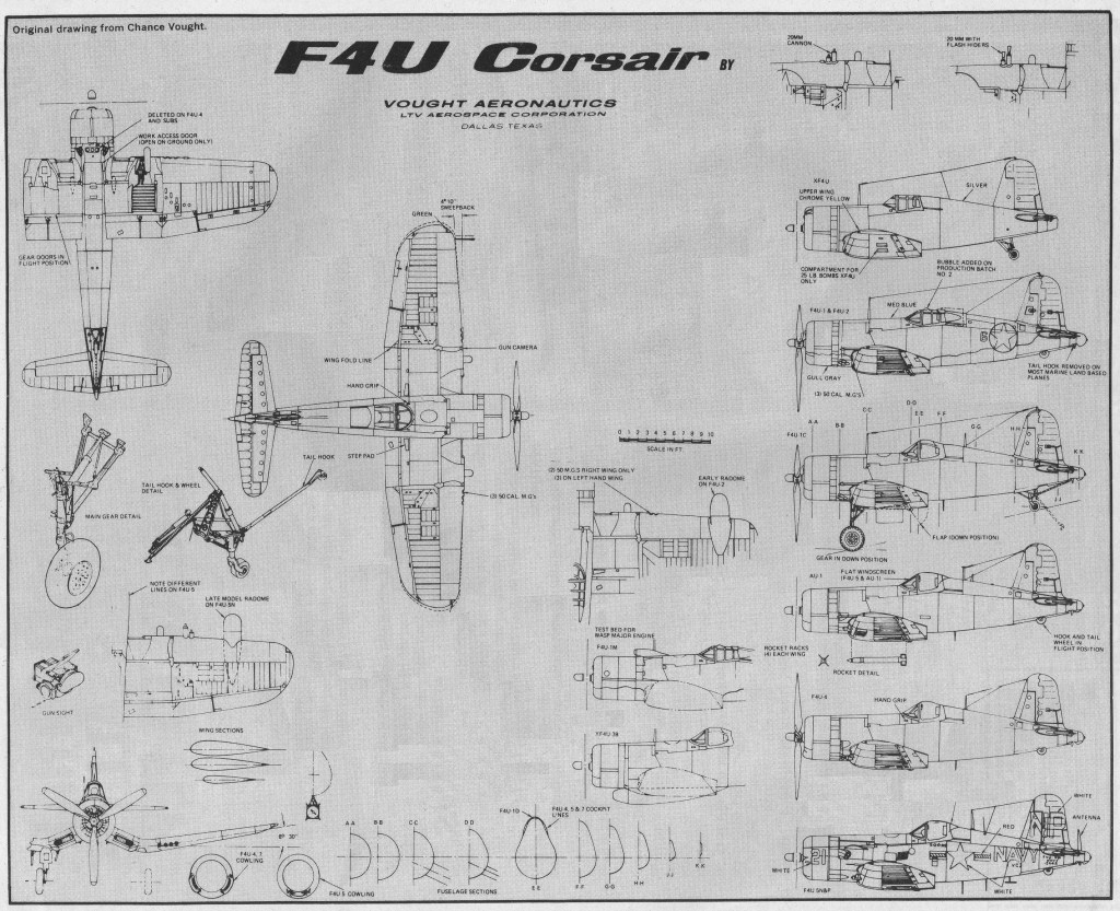
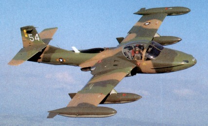
Chance Vought F4U / F2G Corsair Article
Chance Vought won the contract and the project was under way. The Corsair’s first test flight on 29 May 1940 the delay being largely the result of engine development problems resulted in the elevator tabs tearing loose during a high frequency oscillation just above 200 mph. Lyman Bullard Jnr, Chance Vought test pilot, landed the prototype 1443 successfully despite the damage to the control surfaces. On 1 October 1940 the aircraft recorded a ground speed of 404 mph, the first single-engine US military aircraft to exceed that speed (Lockheed P-38 was the first US aircraft).

Some 12,681 of them were built over the following 10 years.
US Navy pilots were enthusiastic about the aircraft’s rate of climb and speed but had reservations about inadequate forward vision during takeoff and landing, a marked tendency to torque stall in carrier approach configurations and a lack of directional stability following touchdown. There appears no doubt that, had the necessity for a high speed carrier borne fighter not been paramount, the Corsair could well have become an also ran. Instead the US Navy issued a contract for 584 units and the first production example flew on 25 June 1942.
The production F4U-1 (V-166B) machines featured the cockpit moved rearwards to make room for the fuel tankage, shifted from the wings to make way for six .50 Browning machine guns, and the even further impaired forward view plus the still unsolved directional instability after landing and the threat of torque stall on approach led the US Navy to decide that the Corsair was unsuitable for combat in the hands of average carrier pilots.
Instead the production delivery (the first -1 in June 1942) was re allocated to the US Marines for land based operations; the first unit (VMF124) flying its first operational mission from Guadalcanal on 1 February 1943 and, within six months, all Marine squadrons in the Pacific had been equipped with the Corsair.
The Marine Corsairs provided immediate protection for the bombing raids on Rabaul, usually flown at 20,000 feet with the P-40s flying below and the P-38 Lightning as top cover above 30,000 feet.
First flying on 25 June 1942, piloted by Boone T Guyton, some 688 F4U-1s (V-166B) were built before a bubble canopy and undercarriage modifications led to the F4U-1A model.
The 1942 F4U-1A was an improved F4U-1 with a P&W R-2800-8, and later 2250hp -8W engine. 688 were built, including 360 to the Fleet Air Arm as the Corsair II and 173 to the RNZAF as Corsair. The wingtips were shortened 6″ and squared-off to fit the lower ceilings of the British carrier hangar decks, and the cockpit was re-arranged with British radio, new seat and harness, other mods.
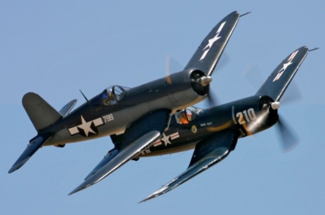
By August 1943 both Goodyear (FG-1 – fixed wing) and Brewster (F3A1) had joined Chance Vought in the production of Corsairs. Goodyear built FG 1Ds were distinguished from the F4U 1D by clear blown canopies, underwing rocket launching stubs and starting courtesy of a electric battery cart rather than cartridges.
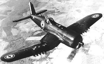
It was at this time that the British Royal Navy gladly accepted 95 early F4U-1 models, designated Corsair Mk.1s, for carrier service. F4U-1B was the temporary production designation for 1943 exports for Great Britain but was never applied in deference to aircraft taken from USN production batches. About 605 went to the Fleet Air Arm as Corsair I, and 370 for the RNZAF. The Royal Navy, after clipping eight inches off each wing to enable the fighters to be fitted underneath the flight deck, operated the Corsair in the European theatre alongside their Fleet Air Arm Wildcats, Hellcats and Seafires.
A total 4,102 of all F4U-1 variants were built. Modified with water injection, raised cockpit, and canopy redesign after the first 1,550 units.

A notable operation was the attack by HMS Victorious-based Corsairs on the German pocket battleship Tirpitz in Kaa Fjord. By April 1944 Royal Navy Corsairs were in operation in the Pacific.
The XF4U-3 of 1946 was an experimental high-altitude fighter version with twin turbochargers. Three prototypes for the Goodyear FG-3 were conversions from F4U-1As 02157, 17516, and 49664.

One F4U-1 was modified in 1944 to a XF4U-3B ground-attack fighter powered by a P&W R-2800-16 with an external turbo-supercharger.
In 1943 five XF4U-4 prototypes with 2450hp R-2800-18W engines were built, 80759 to 80763, plus two were modified from F4U-1A as XF4U-4X, 49763 and 50301, one of which tested with Aeroproducts’ twin counter-rotating props in 1945.
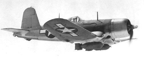
Two hundred F4U-1A were modified from 1943 to F4U-1C close-air-support version with four 20mm cannons. These first saw combat at Okinawa.

The US Navy accepted the F4U-1D in April 1944 for carrier trials – the new designation covering a multitude of modifications such a full plexiglass canopy to replace the metal braced flat sided canopy of the -1, a higher placed pilot’s seat for improved visibility, longer stroked oleos, modified aileron mechanism to improve control at low speeds, and more power from a water injected P&W R2800-8W. The Corsair remained a difficult aircraft for US carrier operations.
Also built as the Goodyear FG-1D the fighter/bomber was equipped with 160-gal drop tank, bomb racks, under-wing rockets. 150 of the F4U-1D were built, going to the Fleet Air Arm as Corsair II and 190 to the RNZAF as Corsair.
After six months the US Navy cleared the Corsair for combat duty, the first operation unit (VF17) flying from New Georgia as a shore-based squadron. It was not until late in 1944 that a Corsair-equipped Marine squadron (VMF124) joined the USS Essex and proved highly successful against Kamikaze attacks. By the end of the Okinawa campaign all US Navy carriers were equipped with Corsairs.
A 1943 night-fighter version, the XF4U-2 was operated by an American specialist unit flying out of Munda on New Georgia with two machine guns removed and an early mark of airborne interception radar (an APS-4) mounted on the right wing leading edge and an autopilot fitted. The XF4U-2 was a conversion from F4U-1 02153.

Thirty-two were converted from F4U-1s by NAF, and two from F4U-1As in the field.
Charles Lindberg, acting as a civilian technical representative for United Aircraft in the Pacific combat area, pioneered the process of doubling the Corsair bomb load from 2000 to 4000 lbs.
Re-introduced in the early -1D were wing leading edge fuel tanks, small 62 gallon unprotected units outboard of the gunbays. Most, later F4U-1Ds differed in having the outboard-wing leading edge fuel tanks deleted and hard points for bombs or external fuel tanks installed under the centre section.
The RNZAF was issued with 424 of these aircraft; thirteen squadrons eventually used the aircraft. Corsairs in RNZAF service did have their problems – predominately centering on the complex hydraulic system, the engine, bombracks, brakes, and ailerons – the main spar of which rotted out after about a year due to water. The F4U-1 wing tanks on the leading edges wept petrol through rivet holes after a few months service due to the vibration of the Brownings, and caused these tanks to be sealed off. This was the primary difference between the F4U-ls and the -1Ds in the RNZAF. FG-1D’s were similar to F4U-1Ds but introduced a clear blown pilot canopy and rocket launching stubs underwing.
With dive brakes extended, the airspeed would stabilise at about 300 knots, but in the clean condition, the aircraft was permitted to indicate 420 knots between 7,500 feet and sea level, which was 470 knots true airspeed.
As early as 1941 the US Navy had requested better high altitude performance from Chance Vought and, in July 1944, the F4U 4 with an uprated Pratt and Whitney R2800 18W engine with water/methanol and driving a four bladed propeller, and new cowl design, made its first test flight. The 4 proved to have a top speed of 425 mph (680 kph) at 28,000 feet, compared with the 1 of 392 mph (630 kph) at 24,000. The first F4U 4 went into service in January 1945, being operated until the end of the Korean War as a carrier borne fighter bomber. Production was also scheduled by Goodyear as FG-4, but the contract was cancelled and none were built.

In 1945 287 F4U-4B were scheduled for the Fleet Air Arm as Corsair I, but were cancelled with the end of hostilities.
Two-hundred and ninety-seven of the 1945 F4U-4C were built, with 20mm cannons.
The 1946 V-354 was a two-place trainer conversion of F4U-1 for Navy evaluation but, with the impending jet age, no contract was offered. USN mark 49763 was possibly assigned, which listed as an F4U-4XA.
Possibly only one of the 1946 F4U-4E night fighter with APS-4 radar was built, and the single F4U-4K was a radio-controlled target.
There was one F4U-4N in 1946 which may have been an upgrade of an F4U-4E with a wing-mounted APS-6 radar.
About 1946, nine aircraft were modified to F4U-4P Photo-recon aircraft.
The F4U-5 was developed to meet a high altitude fighter requirement for the United States Navy in 1947. It differs from the F4U-1 and FG-ID series in a number of respects; a four bladed propeller, twin cheek inlets on the cowling for the side mounted superchargers, metal covered outer wing rear panels (instead of fabric aft of the main spar) to reduce drag and a slightly more bulged canopy to improve rearward vision. The uprated 2850 hp R-2800-32W engine was titled downward 2.75′ to improve stability and forward vision.
Although most contracts for fighters were cancelled at the end of WW2 the Corsair remained in production. Only 5 F4U-5 were built in 1947, 61 in 1948, and 69 in 1949.

The last of 14 F4U-5N was delivered to the US Navy on 22 October 1951. The winterised F4U-5NL had a production run of 100 during 1950-51.
The F4U 5N night fighter variant differs significantly from the 1 model in having different engines, propeller, cowls and exhaust system as well as a later style canopy with a raised section aft.
The XF4U-5 first flew on 4 April 1946 and introduced a new engine. The wings were totally skinned in metal and ailerons were given spring tabs. Heaters were provided for the windshield, gun bays and pitot head. Three were converted from F4U-4. A total of 223 production F4U-5 were built from 1946, featuring all-metal wings.
The 1947 F4U-5P was an armed photo-recon version. Thirty were built: 122167 to 122206.
Similar to the F4U-5, a low altitude version with the R-2800-83W engine and increased armour was originally designated F4U-6, and later AU-1. Built in 1951, the prototype, 124665, first flew on 29 December 1951.

Built from 1952 as a USMC low-altitude fighter and ground support aircraft featuring a narrow cowling, wing oil coolers move to inside fuselage; added armor, and bomb/rocket wing racks. The F4U-6 designation was never applied; redesignated AU-1 instead. 111 went to the USMC squadrons in Korea (129318-129417, and 133833-133843). Veteran aircraft were overhauled and sold to the French AF in 1955.
90 F4U-7 were built in 1952 for the French AF in Indochina. The last prop-driven fighter built in the US.
Forty-four F4U-5N night fighters were built from 194, 124665 to 124709. Some 75 winterised F4U-5Ns were built for service in Korea as F4U-5NLs with wing and empennage boots, propellor de-icer shoes and windshield de-iceing, 124504 to 124560, and 124710 to 124724. The F4U-5N had the APS-19A radar. The last operational Corsairs in United States Navy services were withdrawn in December 1955 and the last of the Reserve Squadron F41J-5s were retired in June 1957.

During the Korean War the US Navy used 27 F4U day squadrons. In addition VC-3 flew F4U-5NL night fighters with attachments on every carrier.
The F2G-1 was the “Sprint” Corsair developed by Goodyear in 1945 using the Wasp Major engine. Only 17 were built. The Goodyear F2G is distinguishable from the Chance-Vought Corsair by having a clear blown canopy.
The last Corsairs to see actual air to air combat were those of the Honduran Air Force during the 11 19 border war between Honduras and El Salvador. On 17 July 1969 a Honduran pilot flying an F4U 5 shot down a P 51D Mustang and two FG 1 Corsairs. The Honduran Corsairs were subsequently sold to collectors in the USA.
The aircraft was used by the French naval air arm during the Suez operations in 1956.
In production from 1941 to 1953, a total of 12,571 were built. Final production on 26 January 1953 ended the longest production record of any airplane built up to that time.
The combat record in the Pacific was 189 F4Us were lost both in combat and non-combat (but excluding training) in destroying 2,140 Japanese aircraft.
Variants:
XF4U-1 – Prototype
VS-317 Modifications on XF4U-1
F4U-1 – Production, seat moved aft 3 ft
VS-321 Modifications on F4U-1
VS-323 F4U-1 with Wright R-3350 engine
VS-324 Modifications on F4U-1
VS-325 Modifications on F4U-1
F4U-1B – Production for British Royal Navy
F4U-1C – Four 20 mm cannon
F4U-1D – Twin pylons for fuel tanks or bombs
F4U-1P – Photographic equipment
XF4U-2 – Special night fighter, radar gear
F4U-2 – modified by Navy as night fighter
VS-331 XF4U-3 – projected turbosupercharger version
XF4U-4 – new engine, propeller, cowling, carberator
V-334 F4U-4 – basic production version
V-336 F4U-1WM (F4U-1 with P&W R-4360 Wasp Major)
V-342 F4U with E engine
F4U-4B – Produced for Royal Navy
F4U-4C – Four 20 mm cannon
F4U-4N – night fighter version
F4U-4P – Photographic version
F3A-1 – Manufactured by Brewster
F3A-1D – Mrewster model of F4U-1D
FG-1 – Manufactured by Goodyear (F4U-1)
FG-1D – Goodyear version of F4U-1D
FG-1E – Radar equipped
FG-3 – Turbosupercharger version
F2G – 3000 hp engine version
XF4U-5 – New P&W engine, supercharger
V-351 F4U-5 – R-2800-32(e) engine, max speed 480 mph
V-354 F4U two seat advanced trainer
V-376 F4U for Perú
V-361 F4U-5 variant
F4U-5N – Night fighter version
F4U-5P – Photographic version
F4U-5NL – Winterised version for Korea
AU-1 – Low altitude attack version, Korean war
F4U-7 – Same as F4U-4 for French Navy
Specifications:
Vought F 4 U Corsair
Engine: Pratt & Whitney R 2800 18W Double Wasp, 2416 hp
Length: 33.661 ft / 10.26 m
Height: 14.764 ft / 4.5 m
Wingspan: 40.912 ft / 12.47 m
Wing area: 313.986 sqft / 29.170 sq.m
Max take off weight: 14672.1 lb / 6654.0 kg
Weight empty: 9205.9 lb / 4175.0 kg
Max. speed: 388 kts / 718 km/h
Service ceiling: 41503 ft / 12650 m
Wing load: 46.74 lb/sq.ft / 228.00 kg/sq.m
Maximum range: 1356 nm / 2511 km
Range: 873 nm / 1617 km
Crew: 1
Armament: 6x cal,.50 mg (12,7mm), 2x 454kg Bomb./ 8x 5″-Rocket
XF4U-1 / V-166A
Engne: P&W XR-2800-4, 1850hp
Prop: 14′ three-bladed
Wingspan: 41’0″
Length: 31’11”
Useful load: 1852 lb
Max speed: 405 mph
Cruise speed: 190 mph
Stall: 73 mph
Ceiling: 35,200 ft
F4U-1 / V-166B
Engine: Pratt & Whitney R-2800-8(B) Double Wasp, 2000 hp
Wingspan: 40 ft 11.75 in / 12.48 m / British 39 ft 7 in
Length: 33’4″
Useful load: 3057 lb
MAUW overload: 14,000 lb.
Max speed: 417 mph
Top speed: 392 mph (630 kph) at 24,000 ft
Cruise speed: 182 mph
Stall: 87 mph
Range: 1015 mi
Ceiling: 36,900 ft
F4U-1A
Engine: P&W R-2800-8, later -18W Double Wasp, 2450 hp
Wingspan: 40 ft 11.75 in / 12.48 m / British 39 ft 7 in
Length: 33 ft 8.25 in / 10.27 m
Empty weight: 8873 lb / 4025 kg
MAUW: 14,000 lb / 6350 kg
Max speed: 395 mph / 635 kph
ROC: 2890 fpm / 880 m/min
Service ceiling: 37,000 ft / 11,280 m
F4U-1D
Engine: Pratt & Whitney R2800-8W Double Wasp, 2000 hp.
Length 33.3 ft. (10.15 m.).
Wing span 41 ft. (12.5 m.).
Weight empty 8,980 lb. (4,070 kg.).
Max wt: 5,465kg (12,039 lb).
Crew 1 pilot.
Armament 6 x 0.50 in. machine guns, 2 x 1,000 lb. (450 kg.) bombs; or 8 x 5 in. (13 cm.) rockets.
Max speed 417 mph (670 kph).
Range 1,015 miles (1,630 km.).
F4U-2 (Naval Aircraft Factory)
Useful load: 2276 lb
Max speed: 381 mph
Cruis speed: 187 mph
Stall: 82 mph
Range: 995 mi
Ceiling: 33,900′
XF4U-3
Length: 33 ft 4in 4
Max speed: 412 mph
Cruise: 180 mph
Stall: 83 mph
Range: 780 mi
Ceiling: 38,400 ft
XF4U-3B
Engine: P&W R-2800-16
XF4U-4
Engine: R-2800-18W, 2450hp
F4U-4
Engine: Pratt & Whitney R-2800-32(E) Double Wasp, 2850 hp
Prop: four-blade
Wingspan: 40 ft 11.75 in / 12.48 m / British 39 ft 7 in
Length: 33 ft 8.25 in / 10.27 m
Useful load: 3215 lb
Max speed: 446 mph
Top speed: 425 mph (680 kph) at 28,000 ft
Cruise speed: 215 mph
Stall: 89 mph
Range: 1005 mi
Ceiling: 41,500′
Armament: six .50 guns, eight wing rockets
Bombload: two 1000 lb
XF4U-5
Engine: Pratt & Whitney R2800-32W Double Wasp, 2850 hp.
Engine: P&W R2800-8W Double Wasp 18-cylinder radial, 2,000 hp
Wing span: 41’0”
Length of 33’4.5”.
Sevice ceiling: 37,000 ft.
Range: 1015 sm
Armament: 4 x 20mm
F4U-5
Engine: Pratt & Whitney R-2800-8(B) Double Wasp, 2000 hp
Wingspan: 40 ft 11.75 in / 12.48 m / British 39 ft 7 in
Length: 33 ft 8.25 in / 10.27 m
Empty weight: 9900 lb / 4490 kg
MAUW: 15,079 lb / 6840 kg
Max speed: 462 mph / 744 kph
ROC: 4800 fpm / 1463 m/min
Service ceiling: 44,000 ft / 13,400 m
Range: 1120 mile.
F4U-5N
Engine: Pratt & Whitney R2800 Double Wasp, 2850 hp.
Length: 34 ft 6 in
Max speed: 470 mph.
Range: 1120 mile.
F4U-5NL
Engine: 2,100 h.p. R2800
Span: 40 ft. l1.75 in
Weight: 13,300 lb.
Max. Speed: 470 m.p.h.
Armament: 4×20 mm. Cannon
F4U-6 / AU-1
Engine: Pratt & Whitney R-2800-83W Double Wasp, 2300 hp
Wingspan: 41’0″
Length: 34’1″
Useful load: 9144 lb
Maxspeed: 440 mph
Cruise speed: 184 mph
Stall: 83 mph
Range: 484 mi
Ceiling: 19,500′
F4U-7
Engine: Pratt & Whitney R-2800-18W Double Wasp two-stage superchargers, 2100 hp
Wingspan: 40 ft 11.75 in
Wing area: 314 sq.ft
Length: 34 ft 6.5 in
Height: 14 ft 9.25 in
Empty weight: 13,426 lb
Normal take-off weight: 13,426 lb
Fuel capacity internal: 195 gal
Fuel capacity external: 2 x 125 gal
Max speed: 450 mph at 25.000 ft
Armament: 4 x 20 mm cannon
Bombload: 4000 lb
F2G-1
Engine: Pratt & Whitney R-4360 Wasp Major, 3000 hp.
Wingspan: 40 ft 11.75 in / 12.48 m
Length: 33 ft 8.25 in / 10.27 m
FG-1D
Engine: Pratt & Whitney R-2800-8W.
AU-1
Engine: 2100 hp Pratt & Whitner R-2800-83WA
Wingspan: 40 ft 11.75 in
Length: 34 ft 6.5 in
Height: 14 ft 9.25 in
Wing area: 314 sq.ft
Empty weight: 10,418 lb
Loaded weight: 13,300 lb
MAUW: 19,398 lb
Max speed: 470 mph
ROC: 4800 fpm
Service ceiling: 40,000 ft
Range: 1120 mi
Armament: 4 x 20mm cannon

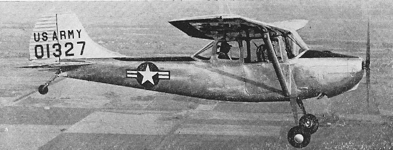
In 1950 five manufacturers entered a competition to replace the fleet of L-4 and L-5 observation planes. The specifications included takeoff and land within 600 feet, cruise at 89 mph, have an observation speed of 49 mph, climb at 800 fpm, three hour endurance, service ceiling of 16,000 ft, and weigh 1000 lb empty.
The Cessna engineers put together the wings from the 170, a tail from the 195 and a new fuselage with transparent panels in the roof and a wider access door and new landing gear, to make the Cessna 305. Cessna’s design was a light-weight strut-braced high-wing monoplane, which provided accommodation for a pilot and three passengers.
Power was from a Continental O-470 of 213hp / 108kW and fixed pitch prop.
The fixed pitch prop limited the cruise to 30% power so as not to overspeed the engine.
The Birddog moved from design sketches to first flight in just 90 days. The landing requirement required 60 degrees of flap and a full stall, three-point landing technique with a high rate of sink. The O-1 is not cleared for aerobatics.
Cessna CE-305 / O-1 Birddog Article
Cessna was awarded the contract with an initial order of 418 aircraft on 29 May 1950. The first military designated L-19s were delivered in December 1951 and sent to Korea, arriving there on 16 February 1951.
The Model 305A differed from the 170 by having the aft fuselage redesigned to give a clear view to the rear and by the provision of transparent panels in the wing centre-section, which formed the cabin roof. A wider access door gave room to load a standard stretcher, for which support brackets were installed. Spring steel landing gear and slotted high lift flaps were fitted along the trailing edge of each wing.
By June 1951 there were 166 L-16s in Korea, and they had amassed about 20,000 hours.
Deliveries of production aircraft began in December 1950, under the designation L-19A and with the name Bird Dog, and by October 1954, 2,486 had been delivered, of which 60 were diverted to the US Marine Corps which designated them OE-1.
An L-19A-IT instrument trainer version was developed in 1953. By 1954 a total of 2486 had been delivered, of which 60 were diverted to the US Marine Corp where they were e-designated OE-1.
In 1956, the Army ordered 100 TL-19D instrument trainers. This was a growth version of the original instrument trainer with a constant-speed prop and a higher gross weight — 2,400 pounds. The next year, the order was expanded by another 207 TL-l9Ds and an uprated version of the basic L-19 was ordered —the “E” model which boosted the higher gross weight and “some minor improvements.”
Sixty Bird Dogs were delivered to the USMC as the O-1B, and the TO-1D is a dual control training version of the O-1A.
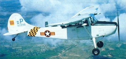
The L-19E was the final version to bring total production of Bird Dogs to 3,431. With redesignation in 1962, the US Army’s L-19A, TL-19D and L-19E aircraft became O-1A, TO-1D and O-1E respectively. The US Marines’ OE-1 became O-1B and this service also acquired 25 of the higher-powered O-1C. US Army trainers, derived from standard production aircraft, had the designations TO-1A and TO-1E.
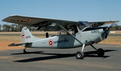
Some O-1 were manufactured by Fuji Heavy Industries for the Japanese Ground Self-Defence Force.
The model 321, or O-1C was an extensively redesigned version of the O-1B Bird Dog for the USMC. The prototype of the O-1C was first flown in 1955 and twenty-five were built. Pilot and observer were protected by flak curtains and seat armour, and all fuel tanks are self-sealing. A 250 lb bomb or three air to surface rockets may be carried beneath each wing. The structure of the O-1C is similar to the O-1B apart from some strengthening for the more powerful engine.
The US Air Force acquired many of the US Army’s O-1s for use by forward air controllers in Vietnam; former TO-1Ds and O-1As were redesignated O-1F and O-1G respectively when equipped for this role.
The O-1Fs were TO-1Ds modified to O-1D standard by deleting the dual controls and rear seat instrument panel and the modified to -F standard by fitting under-wing hard points and army communication gear.
The US Navy ordered 25 of a progressive development designated OE-2. These differ principally in having a longer nose to house a 260 hp Continental SO-370 engine, and taller, more angular tail surfaces.
Cessna had delivered 3,431 examples by the time production ceased including 126 for the French – the bulk of these had been built as O-1s (L-19As), with later variants introducing uprated equipment and the ability to carry wing stores like target marking rockets
Of these, one was a civil prototype and four were evaluation models for civilian use. These were put into service in aerial application and although they got high marks with the dusters, Cessna could not see enough of a market for the aircraft and never put it into production. As far as FAA is concerned, the Birddog is the Cessna 305A and all those converted to civilian use are so designated in FAA records.
O-1s were also built under licence by Fuji in Japan.
Ector Aircraft Co., of Odessa, Texas produced (until stocks of new parts are exhausted) the Ector L-19 Mountaineer and the standard Ector (Cessna) 305. The basic aircraft is delivered with a majored Continental 0-470-11 and the McCauley fixed-pitch prop or with a Continental 0-470-13 or Lycoming 0-540-A4B5, a constant-speed prop and manifold pressure gauge.
Although long since retired from USAF service, a modest number of O-1’s continue to thrive with a handful of air arms across the globe, whilst surplus Bird Dogs have recently enjoyed a renaissance across North America and Australia.
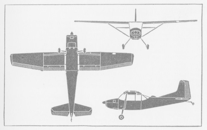
O-1C
Engine: 265 hp Continental O-470-2
Wingspan: 36 ft 0 in
Length: 26 ft 3 in
Height: 7 ft 10 in
Wing area: 174 sq.ft
Empty weight: 1853 lb
Max loaded weight: 2650 lb
Max speed: 185 mph
Econ cruise: 122 mph
ROC: 1300 fpm
Time to 20,000ft: 22.6 min
Range: 575 mi at 10,000 ft
CE-305A
Engine: Continental O-470-11, 213 hp.
Empty wt: 1700 lbs.
MTOW: 2100 lbs (optional): 2300 lbs.
Height: 7 ft 6 in.
Length: 25 ft 9.5 in.
Wing span: 36 ft.
Cruise: (@ 2300 rpm): 78 kts.
Stall: 42 kts.
Cessna L-19E / O-1E Bird Dog
Engine: 1 x Continental O-470-11, 213 hp, 159kW
Wingspan: 10.97 m / 35 ft 12 in
Length: 7.85 m / 25 ft 9 in
Height: 2.22 m / 7 ft 3 in
Wing area: 16.16 sq.m / 173.94 sq ft
Maximum Speed: 130mph (209kmh; 113kts)
Maximum Range: 530miles (853km)
Rate-of-Climb: 1,040ft/min (317m/min)
Service Ceiling: 20,341ft (6,200m; 3.9miles)
Accommodation: 2
Hardpoints: 2
Empty Weight: 1,614lbs (732kg)
Maximum Take-Off Weight: 2,401lbs (1,089kg)
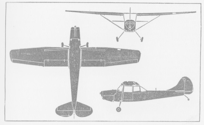
L-19
Engine: Continental O-470-11B, 213 hp
Prop: McCauley 2 blade 90 in fixed pitch
Wingspan: 36 ft
Wing area: 174 sq.ft.
Length: 25 ft 9 in
Height: 7 ft 6 in
Seats: 2
Max gross wt: 2400 lb
Empty wt: 1480 lb
Useful load: 920 lb
Wing loading: 13.79 lb/sq.ft.
Power loading: 11.26 lb/hp
Toatl fuel cap: 42 USG
Useable fuel cap: 36 USG
Baggage cap: 100 lb
Max speed: 179 mph
Cruise 2300 rpm: 104 mph
Stall clean: 44 mph
Stall with flap: 40 mph
ROC SL: 1350 fpm
Service ceiling: 21,300 ft
Takeoff ground roll: 355 ft
Landing ground roll: 320 ft
Cessna L-19A Bird-Dog
Engine: 213 h.p. Continental O-470-11
Span: 36 ft
Length: 25 ft
Height: 7 ft 6 in
Wing area: 174 sq.ft
Empty weight: 1400 lb
Loaded weight: 2200 lb
Max speed: 146 mph at 5000 ft
Cruise: 115 mph
ROC: 1290 fpm
Service ceiling: 21,200 ft
Range: 620 mi
Seats: 2
Cessna O-1G Birddog
Engine: 213hp / 158 kW Continental O-470-11
Fuel: 100 Octane
Wingspan: 36 ft / 10.97 m
Length: 25 ft 9 in / 7.85 m
Height: 7 ft 6 in / 2.29 m
Empty weight: 1,400lbs / 635 kg
Maximum Take-off weight: 2,200lbs / 998 kg
Max speed: 115 mph / 185 kph
Service ceiling: 18,500 ft / 5638.8 m
Max range: 530 mi / 742.08 km
Armament: Eight 2.75 inch (70mm) smoke rockets
Maximum Speed: 131 knots / 151 mph / 243 km/h

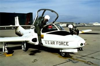
Late in 1952 the USAF formulated a requirement for a jet trainer which would economically permit student indoctrination at an early stage in the training curriculum. Specified design requirements included an empty weight of 4,000 lb (1814 kg) in order to limit both cost and complexity of the aircraft; the ability to undertake twenty take offs and landings within a two hour period; flight handling characteristics matching those of the most modern operational fighters; a 35,000 ft (10668 m) cruise ceiling with sufficient high altitude manoeuvrability to wholly orientate students, and a maximum traffic pattern speed of 113 knots (209 km/h) to assure good low speed handling characteristics. Side by side seating for the student and instructor was favoured. The Marbore II became the Continental J69 and the Cessna company designed their Model 318 around two J69s. This aircraft was a basic jet trainer. In the ensuing design contest, Cessna’s Model 318 was designated the victor early in 1953, and as XT 37s, three prototypes (54 716 to 54 718) were ordered.
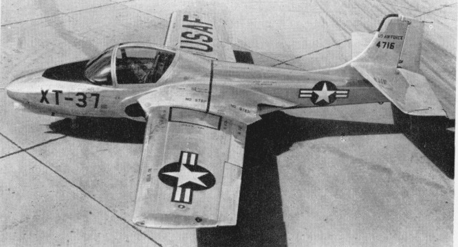
The first of these flew on October 12, 1954, (piloted by Bob Hagen), powered by two Continental YJ69 T 9s (licence built Turbomeca Mabore IIs) with 920 lbf (4.1 kN) thrust each, by which time its manufacturers had been awarded a $5 million contract for eleven pre production T 37A trainers (54 2729 to 54 2739), the first of which flew on September 27, 1955. One of the XT-37 prototypes was lost in a flat spin; the pilot baled successfully. Some strengthening of the wing centre section was found to be necessary, the cockpit layout had to be revised, and field trials with the pre production machines were accompanied by minor teething troubles, among these being the fuel system of the Continental J69 turbojets licence built Turbomeca Marbore IIs, but these were soon overcome, and by the early spring of 1956, contracts had been placed for twenty (55 4302 to 55 4321) and 127 (56 3464 to 56 3590) production T 37A trainers, a contract for a further 123 machines (57 2230 to 57 2352) following shortly afterwards, and the 200th T 37A rolling off the assembly line on July 23, 1958. 534 were built under successive contracts, but were slow in entering service as a result of the need for a number of changes and modifications before they were considered acceptable for training purposes.
The first T-37A was completed in September 1955 and flew later that year. The T-37A was delivered to the U.S. Air Force beginning in June 1956. In the spring of 1957, the first training courses on the T 37A had begun at Waco, Texas, the first class of twenty students receiving 150 hours on the new jet trainer after forty hours on the piston engined Beech T 34A primary trainer. The second group of students at Waco had only twenty hours on the T 34A as the next stage in evolving an all jet curriculum.
In April 1961 all-through jet training was initiated, the pupil flying from the very beginning of his training on T-37 aircraft which had a speed range of 138-684km/h. No catastrophic accident rate resulted, as had been feared by many, but one point which had not been fully considered was the much higher training cost using jet aircraft. There is inevitably a varying pupil rejection rate at the end of primary training, and it was decided in 1964 to revert to light piston-engine trainers, which are much cheaper to operate, for this primary phase, so that T-37 pupils were those left after the first weeding-out.
The T 37A was powered by the 920 lb.s.t. (417 kgp) J69 T 9 turbojet, but during 1959, after the delivery of 416 aircraft of this type, production switched to the T 37B with 1,025 lb.s.t. (465 kgp) J69 T 25 turbojets, and new Onini and UHF equipment, the first of the improved trainers being accepted by the USAF on November 6, 1959. Subsequently, all T 37As passed through a modification programme to bring them up to ‘B’ standards.
For the training role, Cessna chose straight wings, twin wing root mounted engines and side by side seating. The original 417 kg (920 lb) thrust Continental J69 9 engines, built under licence from Turbomeca, were not calculated to make the American type a startling performer.
The T 37B is basically a low wing cantilever monoplane of all metal construction, and has its twin J69 T 25 turbojets mounted in the thickened wing roots, their inboard location creating a negligible change in directional control with one engine inoperative, and facilitating the demonstration of single engine procedures. A single stage, centrifugal compressor engine, the J69 T 25 has a fully automatic altitude compensating fuel control, and the two power plants draw their fuel from the main fuselage tank immediately aft of the cockpit, this being fed from six inter connecting rubber cell fuel tanks in each wing, the total usable capacity of these being 257 Imp. gal. (1 168 lt). Engine driven pumps and submerged booster pumps drive the automatic fuel transfer system, but in the event of a fuel proportioner or electrical system malfunction, fuel is automatically supplied to the engines by the gravity system.
The low ‘sit’ of the T 37B on the ground eliminates the need for cockpit entrance ladders, flush steps in the fuselage 24 in (61 cm) above the ground providing easy entrance from either side of the aircraft. The cockpit itself is ideally situated, well forward of the wing, and, with the backward folding, jettisonable clam shell type canopy offers excellent visibility. The panel itself is a relatively simple and straightforward approach to current requirements. The primary instruments are duplicated for instructor and student, all instruments may be monitored, and all operating controls and switches are easily accessible from either seat. Positioned to port on the student’s side are the navigational and flight instruments, including directional and attitude indicators, altimeter, turn and bank, rate of climb and airspeed indicators, and course indicator. In front of the instructor on the starboard side but within reach of the student are the radio controls, circuit breaker, etc., and the engine instruments mounted over the central quadrant include tachometers, fuel flow and exhaust temperature indicators, fuel and oil pressure gauges, loadmeters and accelerometer. The stick grips and throttle quadrants are of fighter type.
A 1,500 psi (105.5 kg/sq.cm) hydraulic system is installed. Two engine driven, constant displacement hydraulic pumps are used to drive the landing gear and doors, speed brake and thrust attenuators, nosewheel steering system, flaps and stall spoilers. The hydraulically operated brakes are independent of this system. The electrical system comprises two 200 amp. starter generators, one 24 volt, 36 amp hour battery and associated control equipment. No ancillary starting equipment is necessary, the battery being sufficient to provide engine starts for all normal training operations.
Structurally, the T 37B comprises a semi monocoque fuselage, a two spar aluminium alloy wing of NACA 2418 section at the root and NACA 2412 section at the tip, and a normal cantilever monoplane type tail assembly of which the fin is integral with the fuselage, and the tailplane is mounted one third of the way up the fin. Hydraulically operated high lift slotted flaps with a total area of 15.1 sq ft (1.4 sq.m) are mounted inboard of the ailerons which have a total area of 11.3 sq. ft. (1.05 sq.m), and all movable tail surfaces have electrically operated trim tabs. Because of its low drag characteristics, an hydraulically actuated speed brake is located on the underside of the fuselage nose section, aft of the nosewheel well. This brake works in con¬junction with thrust attenuators which deflect the exhaust blast and permit higher rpm during landing approaches. When the attenuators are extended, the resultant effective thrust is reduced by more than forty per cent. Both attenuators and speed brake are controlled by the speed brake switch when the throttles are below seventy per cent rpm. The thrust attenuators automatically retract when the throttles are advanced above seventy per cent rpm.
The undercarriage has two extension systems, the primary system being hydraulically actuated and the secondary system being pneumatically powered. The wheel brakes are, as previously mentioned, operated by a separate hydraulic system controlled by dual rudder and brake pedals, and the wide track of the main members (14 ft 0.5 in. 4.28 m) results in an unusually high degree of ground stability.
The T 37B demonstrates good stability in all configurations and conditions of flight. Extremely effective control surfaces result in instant response, and light forces, well balanced between the three controls, make all manoeuvres easily co ordinated. Spins are mild and recovery by use of standard procedure is positive. The excellent stall characteristics are well defined with lateral control effective at all times, and good stall warning is provided for all flight configurations. Landings are accomplished equally well from either scat, and no abrupt pitch or directional trim change results when power is added for another circuit of the field.
These characteristics are ideal for a training aircraft but they also result in an excellent weapons platform, and supplanting the T 37B trainer on the Wichita assembly line as the T 37C which has underwing attachment points for offensive stores or drop tanks and is intended primarily for supply to the smaller nations militarily aligned with the USA. With a gun sight mounted in the cockpit, underwing racks can carry bombs or rocket, gun or photographic pods for internal security duties, and the T 37C served with such coun¬tries as Portugal (30) and Vietnam. Mission range may be increased to more than 1,100 nautical miles (2 040 km) by the addition of wingtip tanks which, each containing 54 Imp gal. (246 lt), increase the total fuel capacity to 366 Imp gal. (1664 lt). Fuel is transferred from the tip tanks to the wing tanks by inline booster pumps, utilizing the existing internal fuel system, and provision is made for jettisoning.
When production ended in 1977 a total of 1,268 T-37s had been built for the USAF and for export.
During 1962 two Cessna T-37B trainers were evaluated by the USAF’s Special Air Warfare Center to consider their suitability for deployment in the counter-insurgency (COIN) role. These were first tested with their original powerplant of two 465kg thrust Continental J69-T-25 turbojets, at a take-off weight of 3946kg, almost 33% above the normal maximum take-off weight. Subsequently the airframes were modified to accept two 1089kg thrust General Electric J85-GE-5 turbojets. This increase in power made it possible for the aircraft, then designated YAT-37D, to be flown at steadily increasing take-off weights until a safe upper limit of 6350kg was reached.
After successful trials Cessna were requested to convert 39 T-37B trainers from the production line to a light-strike configuration, a contract being awarded in 1966. Designated A 37A, they were delivered, only being withdrawn from service ten years later in 1974. The new model was based on the earlier experiments with the two YAT-37Ds, and equipped with eight underwing hard-points, provided with wingtip tanks to increase fuel capacity and powered by derated General Electric J85-GE-5 turbojets.
Delivery to the USAF began on 2 May 1967, and during the latter half of that year a squadron numbering 25 of these aircraft underwent a four-month operational evaluation in South Vietnam. Following this investigation they were transferred for operational duty with the 604th Air Commando Squadron at Bien Hoa, and in 1970 they were assigned to the South Vietnamese air force.
This led to the conversion of a number of T 37Bs to A 37A Dragonfly status for operational evaluation in Vietnam and followed with development of the much more dedicated A 37B. Production of 577 started in 1968, featuring the General Electric J85 turbojet, airframe stressed to 6g, much increased fuel capacity and eight underwing hardpoints.
Various improvements to the avionics, upgrading of the turbines, the addition of wingtip fuel tanks, and provision for weapons saw the trainer develop into an attack version, and new aircraft were still being delivered for export in late 1977. Featuring side by side seating, the lightjet powered by two General Electric turbojets each rated in excess of 2800 lb static thrust had a range of some 1050 miles on a tankage of 1100 litres. Armed with a mini gun in the nose and with four pylons on each wing for ordinance and stores, the A 37 could feature a typical delivery of four 8701b bombs, two 600 lb bombs and two 500 lb bombs. A load could consist of an assortment of fire bombs, demolition bombs, canister clusters, flares or rockets. The aircraft could, it is claimed, carry their own weight in stores.
During this period, Cessna had built the Model 318E prototype of a purpose-designated light-strike aircraft based on the T-37 and this flew for the first time in September 1967.
The initial production batch of this A-37B was started quickly enough for the first deliveries to begin in May 1968.
The A-37B differed in construction from the prototype YAT-37D, its airframe stressed for 6g loading, maximum internal fuel capacity increased to 1920 litres with the ability to carry four auxiliary tanks having a combined capacity of 1516 litres, and with provision for flight-refuelling.
The engines were changed to two General Electric J85-GE-17A turbojets of 2585 kg (5700 lb) total installed thrust. The tip tanks became standard, a GAU-2B/A 7.62mm Minigun was installed, and eight underwing hardpoints. The two inner of these can each carry 395 kg (870 lb), the intermediate ones 272 kg (600 lb) and the outers up to 227 kg (500 lb) although the maximum weapon load is 2576 kg (5680 lb) with a maximum takeoff weight of 6350 kg (14000 lb).
For the assessment of results both gun and strike cameras were carried, and some armour protection for the crew of two was provided by the inclusion of layered nylon flak-curtains installed around the cockpit.
The avionics is limited to comprehensive but basic navigation/communications and a non computing gunsight. A Forward Air Control variant existed as the OA-37B.
By the time production ended in 1977, 577 A-37Bs had been delivered. The Cessna Model 318E Dragonfly (A-37B) is equipped with two General Electric J85-17A turbojets, giving it almost double the takeoff power (each rated in excess of 2,800 lbs static thrust), and subsequently double the takeoff weight, over that of the T-37. Increasing the number of and strengthening the hard points, enables the A-37B to carry close to its own empty weight in armament (around 5000 lb).
The last T-37B was officially retired from active USAF service on 31 July 2009
The US Government supplied 254 Cessna A37B Dragonfly’s to the Vietnam Air Force (VNAF) during the Vietnam War. After the fall of South Vietnam in 1975, ninety-five VNAF A37B aircraft were captured and incorporated into the Vietnamese People’s Air Force. Many were transferred to the US Air National Guard.
More than 600 were delivered at home and abroad, including sales to Brazil, Chile, Guatemala, Honduras, Peru, Thailand.
Military Users: (All models) Brazil, Cambodia, Chile, Columbia, Ecuador, Guatemala, Greece, Honduras, South Korea, Pakistan, Peru, Portugal, Thailand, Turkey, South Vietnam, Vietnam, USAF (and Luftwaffe via US training programme).
Variants:
XT 37 CE
Three prototypes of the Model 318, first flown October 12, 1954. Powered by two Continental YJ69 T 9s (licence built Turbomeca Mabore IIs) with 920 lbf (4.1 kN) thrust each.
T 37 CE
Pre production batch of eleven airframes. All subsequently redesignated as T 37A CEs.
T 37A CE
Cessna Model 318A, production standard. Two Continental T69 T¬9s. Production came to 444 units, survivors up graded to T 37W CE. Single example to JT 37A CE for special test. T 37 universally known as the Tweety Bird or Tweet in USAF service.
T 37B CE
Further improved production standard, improved radio/navigation installation and J69 T 25s. Model 318B, 552 built.
T 37C CE
Version of T 37B CE for Military Assistance Program countries. Provision for underwing pylons and tip tanks optional. 198 built.
YAT 37D CE
Two T 37C CEs converted to counter insurgency aircraft with six underwing hardpoints and two General Electric J85 GE 5s. Both redesignated YA 37A CE. Cessna Model 318D.
A 37A CE Dragonfly
‘Production’ version of YA 37A CE with eight underwing hardpoints and 7.62mm Minigun in nose. 39 T 37B CE converted.
A 37B CE Dragonfly
New build version, as A 37A CE but with J85 GE 17A, increased fuel, provision for in flight refuelling and strengthened airframe. 577 built of which one was termed YA 37B CE for development work.
OA 37B CE Dragonfly
At least 122 A 37Bs redesignated for use by Air National Guard units in the Forward Air Controller role.
Specifications:
T 37A
Engines: Two Continental T69 T¬9
Wing span: 33.78 ft ( 10.3 m).
Overall length: 29.25 ft ( 8.9 m).
Height: 9.17 ft ( 2.8 m).
Wing area: 183.9 sq.ft ( 17.1 sq.m).
Wing aspect ratio: 6.20.
Empty wt: 4056 lb ( 1841 kg).
Normal T/O wt: 6574 lb ( 2984 kg).
MTOW: 6574 lb ( 2984 kg).
Internal fuel cap: 257 Imp.Gal. (1168 lt).
External fuel cap: 108 Imp.Gal. (490 lt).
Wing loading: 35.7 lb/sq.ft ( 174 kg/sq.m).
Pwr loading: 3.7 lb/lbst ( 3.7 kg/kgst).
Max speed: 452 mph ( 727 kph).
Initial ROC: 3000 fpm ( 15 m/sec).
TO dist 50 ft: 2025 ft ( 617 m).
Range: 935 sm ( 1500 km).
T-37A
Engines: 2 x Continental J69-T-15, 920 lb
Wingspan: 33 ft
Length: 27 ft 1 in
Height: 8 ft 9.25 in
Wing area: 181.8 sq.ft
Empty weight: 3116 lb
Loaded weight: 5600 lb
Max speed: 393 mph at 35,000 ft
Cruise: 310 mph
ROC: 3000 fpm
Service ceiling: 39,800 ft
Max range: 935 mi
T 37B
Engine: 2 x Continental J69 T 25 turbojets, 1,025 lbs.t. (465 kgp).
Span, 33 ft 9.5 in (10.3 m)
Length, 29 ft 3 in (8.93 m)
Height: 9.19ft (2.80m)
Wing area, 183.9 sq.ft (17.09 sq.m).
Gross weight: 6,574 lb 2 982 kg
Empty wt: 4,056 lb (1840 kg).
Take off dist to 50 ft. (15 m): 2,025 ft. (617 m).
ROC S/L Military RPM: 3370 fpm (17 m/sec).
Service Ceiling Military RPM: 38,700 ft (11 796 m).
Single engine Service Ceiling ½ Fuel Military RPM: 25,000 ft (7 620 m).
Cruise speed Normal rated power, ½ fuel at 35,000 ft (10 668 m): 320 kts (593 kph).
Max speed ½ fuel Military RPM at 20,000 ft (6 096 m): 369 kts (684 kph)
Range at 35,000 ft (10 668 m) at 289 kts (535 kph): 692 nm (1282 km).
Max range 5% reserve at 35,000 ft (10 668 m) at 289 kts (535 kph): 809 nm (1 499 km).
Range at normal RPM with 5% reserves at 35,000 ft (10 668 m) at 313 kts (580 kph): 755 nm (1390 km).
Landing Distance from 50ft (15 m): 2,600 ft (792 m).
Stalling speed gross weight, SL: 74 kts (137 kph).
T-38C – Engine: 2 x Continental J69 T 25 turbojets, 1,025 lbs.t. (465 kgp).
Span, 33 ft 9.5 in (10.3 m)
Length, 29 ft 3 in (8.93 m)
Height: 9.19ft (2.80m)
Wing area, 183.9 sq.ft (17.09 sq.m).
Armament: 2 x 250lb Iron Bombs
Rate-of-Climb: 3,370ft/min (1,027m/min)
Service Ceiling: 39,199ft (11,948m; 7.4miles)
Accommodation: 2
Hardpoints: 2
YAT 37D
Engine: 2 x General Electric J85 GE 5 turbojet, 2,400 lb.s.t. (1 088.6 kgp).
Gross weight: 10,500 lb. (4 763 kg).
Take off dist: 1,000 1,700 ft (305 518 m).
Ordnance: 3,000 lb. (1361 kg).
Max speed: 475 mph (764 km/h) clean
Max speed: 320 mph (515 km/h) max external ordnance and wingtip tanks.
A 37 Dragonfly
Engine: 2 x Continental J69-T-25, 4562 N / 465 kp
Length: 29.298 ft / 8.93 m
Height: 9.35 ft / 2.85 m
Wingspan: 33.793 ft / 10.3 m
Max take off weight: 6401.1 lb / 2903.0 kg
Max. speed: 370 kts / 686 km/h
Service ceiling: 38714 ft / 11800 m
Range: 1150 nm / 2130 km
Crew: 2
Cessna A37B Dragonfly
Engines: Two General Electric J85-17A Axial Flow turbojets, 2,850 lbs (1293kg)
Wingspan: 10.93 m / 35 ft 10 in over tip tanks
Wing Area: 193.5 sq. ft / 17.98 sq. m
Length: 8.62 m / 28 ft 3 in
Height: 2.71 m / 8 ft 11 in
Empty weight: 6,254 lb / 2,843 kg
Maximum Takeoff weight: 14,000 lb / 6,364 kg
Maximum landing weight: 6350 kg (14 000 lb)
Wing Tank Capacity: 2 x 83 Imperial Gallons / 376 Litres / 99 U.S. Gallons
Fuselage Tank Capacity: 2 x 66 Imperial Gallons / 299 Litres / 79 U.S. Gallons
Wingtip Tank Capacity: 2 x 75 Imperial Gallons / 341 Litres / 90 U.S. Gallons
Pylon Tank Capacity: 4 x 81 Imperial Gallons / 367 Litres / 97 U.S. Gallons
Maximum Speed: 420 knots / 483 mph / 778 km/h
Cruise Speed: 265 knots / 305 mph / 491 km/h
Cruise at 25,000 ft: 489 mph (787 km/h).
Rate-of-Climb: 6,990ft/min (2,131m/min)
Service Ceiling: 41,762ft / 12,729m
Range w/max.fuel: 1629 km / 1012 miles
Range w/max.payload: 740 km / 460 miles
Take off run: 1740 ft.
Landing dist: 1710 feet.
Armament: One GAU-2B/A 7.62mm Minigun
Hardpoints: 8


Dwane Wallace and his company perceived the untapped twin engine market as being for a relatively inexpensive and uncomplicated airplane. The prototype T 50 was a simple airplane. It had fixed ¬pitch props and small (225 hp) Jacobs en¬gines, but constant speed propellers and 20 more horsepower per side were later fitted. The props were not full feathering, and could only be pulled into full coarse pitch in the event of an engine failure.
The design used al¬most no aluminum (only the nose cap, tail stinger, engine cowlings and nacelles) at a time when aluminum was far too valuable to waste on trainers. The T 50’s fuselage was welded steel tubing with fabric over wood longerons and formers, and the wing was all wood spruce, mahogany and birch under fabric. The flaps were wood also, and they and the gear were both driven through bicycle -chain loops by a pair of electric motors in the belly. The screw jack actuator for the gear was non-reversible, so no down locks or up¬latches were needed. The landing gear retracts upward into the nacelles and remains partly exposed so that belly landings can be made with little or no damage if the flaps are up. An unusual feature of the Jacobs engine is that it operates on only one magneto, plus battery ignition. It is started on the battery, then switched to the mag. Both engines turn generators, and they run smoothly on ignition if a mag fails.
The T-50 prototype makes its first flight with Dwane Wallace at the controls on March 26, 1939. The plane was certified in December 1939.
By 1940, it was in production and ready for buyers. Cessna only had time to make a few commercial T 50s before rumors of war reached American ears. The Army showed a polite interest in the T 50 as a trainer for bomber pilots, and ordered 33 specially equipped T-50’s – at the time, the largest order in Cessna’s history. The Army’s new planes are designated AT-8’s. The Army Air Corps’ first Bobcats were AT 8s, and they were, in fact, the service’s first multi-engine trainers of any sort. The AT¬8 had 290 hp nine cylinder Lycomings in place of the civilian airplane’s seven cylinder 220kW / 245 hp Jacobs R-680-9 engines, plus the eyebrow windows and transparent cockpit roof that henceforth all military T 50s would have. Service trials showed that these were unnecessarily powerful for use in a two-seat trainer, and when in 1941 the first real production contracts were placed, less powerful engines by the same manufacturer were specified.
The British decided to ship their students to Canada for flight instruc¬tion, so it fell to Canada to come up with the necessary training planes. Prior to that, they’d sold four to the CAA [as airways fa¬cility check planes] and 33 to the Air Corps, but the big sale was the first 180 airplanes to the Canadians dubbing them “Cranes”.
The Canadians called the T¬50s Cranes and eventually got 830 airplanes. One extra thing the Canadians wanted was a third fuel tank, installed in the fuselage be¬neath the rear seat; the two 60 gallon wing tanks were only good for about three hours, and 40 gallons in the fuselage gave the Crane an extra hour or so. The Crane wasn’t certified for civilian use with the third tank, and the filler cap opening was covered over in surplus Canadi¬an T 50s (and later U.S. versions that also got the mod) after the war. The Canadians soon reverted to wooden fixed pitch props, because of a lack of metal for blades and perhaps because they figured the airplane was going nowhere but down anyway if an engine stopped. For the Commonwealth Joint Air Training Plan, eventually 550 aircraft were supplied under Lend-Lease.
The original use of Cessna’s T-50s had been in a light transport role, and in 1942 the USAAF decided that these aircraft would be valuable for liaison/communication purposes and as light personnel transports. The aircraft were named Bobcat and given the designation C-78, later changed to UC-78. In addition, a small number of commercial T-50s were impressed for service with the USAAF under the designation UC-78A.
The USAAF’s requirement for the two-seat conversion trainers had been difficult to predict, and when it was discovered in late 1942 that procurement contracts very considerably exceeded the training requirement, Cessna was requested to fulfil the outstanding balance of the AT-17B and AT-17D models as UC-78B and UC-78C Bobcats respectively. Both were virtually identical, but differed from the original UC-78s by having two-blade fixed-pitch wooden-propellers and some minor changes of installed equipment. Production of these two versions amounted to 1,806 UC-78Bs and 327 UC-78Cs. (3,370 UC-78 Bobcats for the USAAF in total)
The initial production version, designated AT-17, was equipped with Jacobs R-755-9 engines driving wooden propellers. A total of 450 was built, and these aircraft were followed into production by 223 of the generally similar AT-17A, which differed by having Hamilton-Standard constant-speed metal propellers and a lighter maximum weight. The later AT-17B (466 built) had some equipment changes, and the AT-17C (60 built) was provided with different radio for communications. Of these 1,199 aircraft, 550 were delivered to Canada with the name Crane Mk 1A.
They came in two gross weights, de¬pending on the wing construction used¬ – 5,100 and 5,700 pounds and their crew capacity was either two or five, depending on whether they had the fuselage aux tank.
In the period 1942-3, the US Navy had a requirement for a lightweight transport aircraft to carry ferry pilots between delivery points and their home bases, as well as for the movement of US Navy flight crews. This led to the procurement of 67 aircraft, generally similar to the UC-78, which entered service under the designation JRC-1. Many examples of USAAF Bobcats remained in service for two or three years after the end of World War II.
Originally built with 245 hp Jacobs radial engines, some Bobcats later got 295 hp Lycomings, and others were re-engined with 300 hp Jacobs powerplants. With the addition of an exit-hatch window to meet safety requirements, some also have been converted to six-seaters, though normal seating is two pilots and three passengers on a single bench-type rear seat.
Bobcats have a large rudder, but the vertical stabilizer is small and minimum single-engine control speed is 90 mph. At 10,000 feet, full throttle gives 20″ of manifold pressure, and 1,900 rpm on the Hamilton Standard constant-speed props will yield 143 mph indicated.

There are four different single engine ceilings listed for the heavier of the two versions of the airplane, based on gross weights of 5,400 and 5,700 pounds, each calculated with fixed pitch and constant speed props. The best is 1,500 feet above sea level; the worst is sea level, with a minimum rate of descent of 50 feet per minute.
There were several little ¬known Bobcat variants and derivatives, though none of them ever progressed much beyond the prototype stage. The first was the Cessna P 7, a Bobcat with plywood covered wings and tail surfaces and 330 hp Jacobs engines. The second was the P 10, a Wichita mini-version of the de Havilland Mosquito, it was a two place P 7, with the big Jacobs en¬gines and a plywood covered fuselage, a little snub nose and a pair of side by side seats un¬der a bubble windscreen and roll back cano¬py. Finally, there was the P 260, which had the Bobcat’s wing planform, fabric covered fuselage arrangement and formation of boil¬ers nacelles; but it was a 14,000 pound car¬go hauler with R 1340 Pratt & Whitneys. It almost made it into production the Govern¬ment was about to buy 500 of them as C¬106As except the C-47 turned out to be more useful than any¬body had expected.
In early 1944, Cessna suspends production of the Bobcat and begins manufacturing components for the Douglas A-26 and Boeing B-29 bomber. More than 5400 T-50s were constructed for the RCAF and the US military.
Cessna T-50 1A
Engine: 2 x Jacobs L-4MB, 225 hp
Wingspan: 41ft 11in (12.8m)
Length: 32ft 9in (10m)
Height: 9ft 4in (2.8m)
Range: 750 miles (1,207km)
Speed: 191 mph (307 km/h)
Cessna UC 78 Bobcat
Engine: 2 x Jacobs R 755-9, 242 hp
Length: 32 ft 9 in / 9.98 m
Height: 9 ft 11 in / 3.02 m
Wingspan: 41 ft 11 in / 12.78 m
Wing area: 295.041 sqft / 27.410 sq.m
Max take off weight: 5699.9 lb / 2585.0 kg
Weight empty: 3501.5 lb / 1588.0 kg
Max. speed: 170 kts / 314 km/h / 195 mph
Cruising speed: 152 kts / 282 km/h
Service ceiling: 22,000 ft / 6705 m
Wing load: 19.27 lbs/sq.ft / 94.00 kg/sq.m
Range: 652 nm / 1207 km / 750 miles
Crew: 2
Passenger: 3
UC-78 Bobcat
Engine: 2 x Lycoming R-680-9 radial, 220-kW (295-hp).
JRC-1
Engine: 2 x Lycoming R-680-9 radial, 220-kW (295-hp).
Crane Mk I
Engine: 2 x Lycoming R-680-9 radial, 220-kW (295-hp).
Crane Mk 1A
AT-8
Engine: 2 x Lycoming R-680-9 radial, 220-kW (295-hp).
AT-17
Engines: 2 x Jacobs 8-775-9, 183kW (245 hp).
Wingspan: 12.80m (41 ft 11 in).
Length: 10m (32ft 9in).
Max TO weight: 2258 kg (5,700 lb).
Gross weight: 5,700 lb.
Empty weight: 4,050 lb.
Fuel capacity: 120-160 USG.
Max speed: 195 mph at sea level.
Cruise: 165 mph.
Landing speed: 65 mph.
Initial climb rate: 1,525 fpm.
Ceiling: 15,000 ft.
Operational range: 750 miles.
Seats: 4-6.
AT-17A
AT-17B
AT-17C

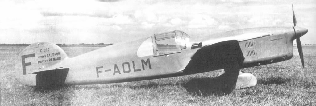
A fighter trainer based on the Coupe Deutsche de la Meurthe racers of 1933 35, the C.690 was the first of a series of little Caudron fighters which were among the most successful light fighters of the period between the World Wars. Powered by a six-cylinder in line air cooled Renault of 240 hp, the C.690 had fixed spatted landing gear and length greater than the span. One machine¬gun could be fitted. Subsequent developments in the series, which included the C.710, C.713 Cyclone, C.714 and Caudron-Renault C.760, were brought to a halt by the German occupation of France in 1940.
Fifteen C 690Ms were built as advanced trainers for the Armee de I’Air.
Engine: Renault, 240 hp
Span: 7.75 m (25 ft 5 in)
Length: 7.85 m (25 ft 9 in)
Gross weight: 990 kg (2185 1b)
Maximum speed: 370 km/h (229 mph)
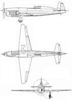

The Caudron C.59 was a French, two-seat biplane with a single engine and a canvas-covered fuselage. The French aircraft manufacturer Caudron made this aircraft between 1922 and 1924. It was suitable for several purposes.
Training aircraft intermediate preparation Caudron C.59 was developed with the assistance of Paul Deville René Talpina, the aircraft has a wooden frame and fabric covering. The ailerons were present only on the upper wing. The student was placed in an open cockpit under the central section of the upper wing, and instructor cabin was directly behind him under the back edge of the wing. The aircraft had dual controls standard.
The prototype flew in August 1921 and after extensive testing was ordered in large quantities for the French Air Force in seven contracts. More than 1,000 aircraft were manufactured and supplied to the French army and remained in service for 15 years.
A large batch of 32 was sold to Turkey. The aircraft arrived at their destination within 1924 to 1926 and were numbered 801-832. The main base was stationed Eskisehir Hava Okulu, where they were widely used until 1936. Then, they gradually began to be replaced by German Gotha Go.145. By the time they complete the withdrawal of the Air Force in 1937, only 7 machines remained in operation. They were handed over to the TNC (Turkish Aviation League), where they remained until 1941.
The Finnish Air Force purchased three Caudron C.59s from France in 1923. The aircraft first carried the air force designation codes 2E3-2E5 and from 1927 on CA-48 – CA-50. The manufacturing numbers of the aircraft were 5407–5409. The aircraft were equipped with landing gear, but there were at least one aircraft (2E3) was fitted with floats. The aircraft were accepted into service on March 8, 1923 and the last one was taken out of service in 1931.
The Caudron C.59 was also used in Bulgaria, China, and in the Spanish Civil War.
There was also a C.59/2 version, which was equipped with a 230 hp (170 kW) Lorraine 7Ma Mizar engine and had a wide track undercarriage.
More than 1,800 Caudron C.59s were manufactured.
Variants
C.59
Original design.
59/2
Fitted with 230 hp (170 kW) Lorraine 7Ma Mizar radial engine.
C.320
c.1932, Original C.59s but refitted with 250 hp (190 kW) Renault 9A 9-cylinder radial engine. Some later returned to their original Hispano engines.
Operators:
Argentine Air Force
Brazilian Air Force
Bulgarian Air Force
Republic of China Air Force
French Air Force
French Navy
Finnish Air Force
Portuguese Air Force
Romanian Air Force
Spanish Republican Air Force
Spanish Air Force
Turkish Air Force
Venezuelan Air Force
Engine: 1 × Hispano-Suiza 8Ab, 134 kW (180 hp)
Wingspan: 10.24 m (33 ft 7 in)
Wing area: 26.00 sq.m
Length: 7.80 m (25 ft 7 in)
Height: 2.90 m
Empty weight: 700 kg (1,543 lb)
Gross weight: 988 kg (2,178 lb)
Maximum speed: 170 km/h (106 mph)
Endurance: 3 hr 30 min
Cruising speed: 138 km / h
Practical range: 500 km
Practical ceiling: 5500 m
Crew: 2
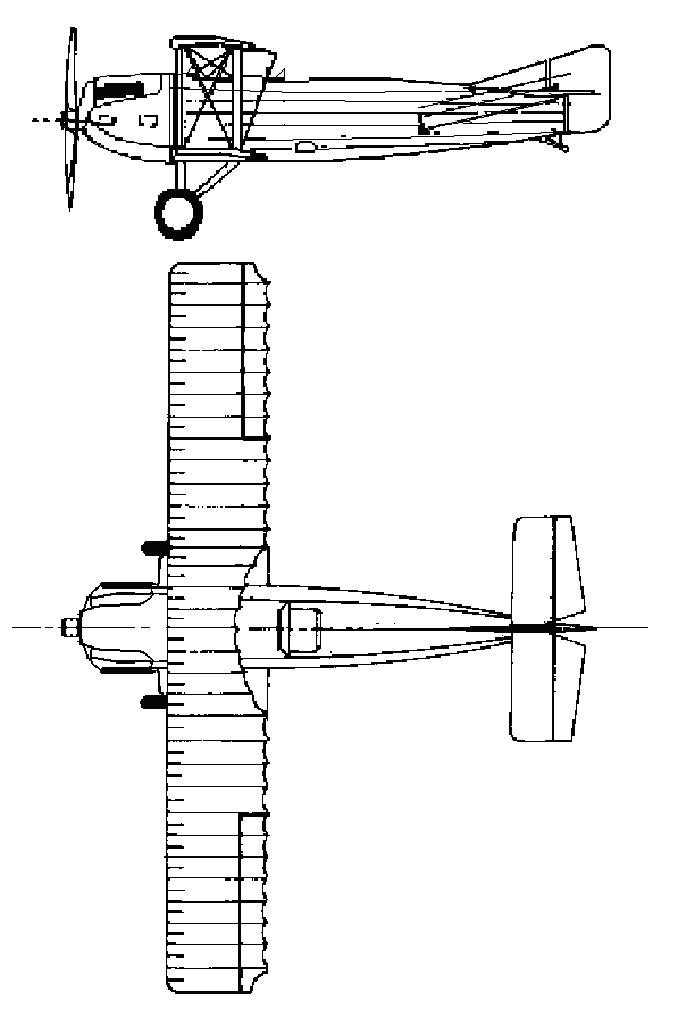
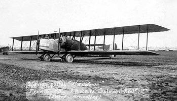
The P.23 was designed by Paul Deville to be a night bomber able to reach Berlin with a 600 kg (1,323 lb) bomb load. The French BN2 military category indicated a two seat night bomber but the P.23 had a crew of three. It had a much in common with the Caudron C.22 but was almost 50% larger in span, requiring an extra bay and more powerful engines. It was a large five bay biplane, with fabric covered, constant chord, unswept wings with angled tips. The upper wing, which carried the ailerons, had a slightly greater (4%) span and a smaller chord. There was no stagger, so the sets of parallel interplane struts were vertical; flying wires braced each bay. Pairs of V-form engine bearing struts, which supported the two cowled 194 kW (260 hp) Salmson 9Z nine cylinder water-cooled radial engines just above the lower wing, defined the inner two bays.
The P.23 had a flat sided fuselage. There was a gunner’s position in the nose, equipped with twin Lewis guns. A roomy open cockpit was positioned under the wing leading edge, with a separate gunner’s cockpit behind it under a large, rounded trailing edge cut-out. This was fitted with another pair of Lewis guns and a further gun firing downwards through a trapdoor in the floor. A low, broad fin carried a broad balanced rudder which extended down to the keel. The tailplane, angular in plan and of very low aspect ratio, was mounted on top of the fuselage and its elevators had a cut-out for rudder movement.
The bomber had a fixed tailskid undercarriage, with mainwheels in pairs . Their axles were mounted on longitudinal bars attached to the wing under the engines by N-form struts.
The Caudron C.23 first flew in February 1919, piloted by Jules Védrines. Higher power engines, the 447 kW (600 hp) Salmson 18Z or the 224 kW (300 hp) Hispano-Suiza 8Fb, were considered in April 1918 but the Salmson was not yet fully developed and trials of the Hispano led nowhere.
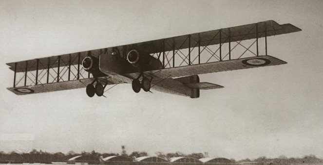
The P.23 received orders for a total of 1000 under the designation C.23BN.2, but by the time of the Armistice in November 1918 fifty-four C.23s had been delivered and its serial production canceled. Some served with the 22nd squadron, stationed in Lyuksoyle, until their replacement by the more powerful Farman Goliath in February 1920.
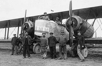
Very soon after the war some C.23s not used by the French Air Force were modified to carry twelve passengers in an open cockpit formed by an opening between the cockpit and mid-upper gunner’s position. On 10 February 1919 one made the first passenger flight between Paris and Brussels, carrying five passengers tightly packed together in an open cockpit. One C.23, designated C.23 bis, was modified to carry fifteen passengers internally, flying between Paris and London.
Védrines and his engineer Guillian were killed in a C.23 when an engine failed whilst trying to establish a route from Paris to Rome.
Variants:
C.23 BN2
Bomber
C.23
12 seat transport
C.23 bis
15 seat cabin transport
Specifications:
C.23 BN2
Engines: 2 × Salmson 9Z 9-cylinder, 190 kW (260 hp)
Propellers: 2-bladed
Upper wingspan: 24.50 m (80 ft 5 in)
Lower wingspan: 23.57 m (77 ft 4 in)
Wing area: 107 sq.m (1,150 sq ft)
Length: 13.00 m (42 ft 8 in)
Height: 3.40 m (11 ft 2 in)
Empty weight: 2,341 kg (5,161 lb)
Gross weight: 4,170 kg (9,193 lb)
Fuel capacity: 980 lt (216 imp gal; 259 US gal) and 132 l (29 imp gal; 35 US gal)
Maximum speed: 143 km/h (89 mph; 77 kn) at sea level
Cruising speed: 122 kph
Stall speed: 82.2 km/h (51 mph; 44 kn)
Endurance: 6.75 hr
Service ceiling: 3,500 m (11,483 ft)
Time to altitude: 41 min to 4,000 m (13,123 ft)
Crew: Three
Armament: two 7.7-mm machine gun Lewis
Bombload: 600 kg (1,323 lb)