In 1943, the Australian government arranged for the Commonwealth Aircraft Corporation (CAC) to manufacture the Mustang Mk IV (P-51D) under licence from North American Aviation. The RAAF urgently needed a new fighter, and so the first CAC Mustangs were built mainly from imported semi-finished parts. A prototype Mustang, A68-1001, was used for development trials and the first Australian production Mustang, A68-1, flew on 29 April 1945. This aircraft was handed over to the RAAF on 4 June 1945 and was used for trials by No 1 Aircraft Performance Unit until October 1946. It was placed in storage until 1953 when it was delivered to the Department of Supply at Woomera.
The first 80 Mustang 20s (A68-1/80) were delivered with Packard Merlin V-1650-3 engines, under the CA-17 designation. A second contract called for 170 improved Mustangs, but only 120 were completed. Known as CA-18, the first 40 were built as Mustang 21s (A68-81/120) with Packard Merlin V-1650-7 engines. The remaining CA-18s comprised 14 Mustang 22s (A68-187/200) with Packard Merlin V-1650-7 engines. A CA-21 contract for a further 250 Mustangs was cancelled and, in lieu of the remaining CA-18s and CA-21s, 298 lend-lease P-51Ds and Ks were taken on strength (A68-500/583 and A68-600/813). In addition, the RAAF also accepted Mustangs for the Netherlands East Indies Air Force (N3-600/640).
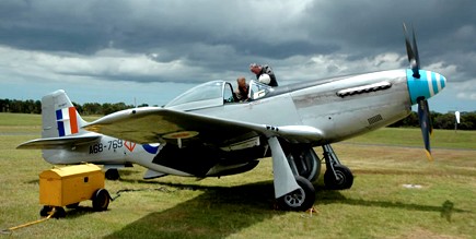
CAC-21 Mustang VH-MFT
Produced too late for World War II, RAAF Mustangs were assigned to Japan for occupation duties and, early in 1946, Nos 76, 77 and 82 Squadrons flew into Iwakuni. In 1949 Nos 76 and 82 Squadrons withdrew to Australian and the Mustangs of No 77 Squadron remained to take part in the Korean War from June 1950 until April 1951, when they were replaced by Gloster Meteors. In Australia, Mustangs remained in service with Citizen’s Air Force Squadrons until they were withdrawn from service in 1959.
CAC CA 18 Mustang Mk 21 Engine: One Packard Merlin V1650-7, 1490 hp at sea level, 1720 hp at 6300ft & 1565 hp at 17250 ft. Propellor: Hamilton Standard 4 Bladed Constant Speed Propellor diameter: 11ft 2in (3·4m). Span 11.28 m (37 ft) Length 9,83 m (32 ft 3 in) Height: 3.71 m (12 ft 2 in). Empty weight: 3567 kg (7863 lb) Maximum Take Off Weight: 10,500 pounds or 4763kg. Internal Fuel Capacity 224 Imp Gallons / 1018 litres External drop tanks of 75 US Gals (284 litres) & 110 US Gals (416 litres). Max IAS/Mach all altitudes: 438 kts IAS/Mach 0.77 Vne at 9,000ft: 500 kts TAS / 925 km/h Max speed straight and level 10,000ft: 348kts TAS / 643 km/h Max speed straight and level 25,000ft: 380kts TAS / 703 km/h Maximum Rate of Climb: 3475ft/min at 5000ft Service ceiling: 41900 ft / 12771 metres. Time to 20000ft: 7·3 mins Time to 30000ft: 12·6 mins. Maximum Range 25000 ft internal fuel: 840 nm / 1530 km. Maximum Range 25000 ft external fuel: 1435 nm / 2655 km. Armament: Six 0.50 in Colt Browning machine guns; two 454 kg (1000 lb) bombs or up to 10 rockets Inboard guns contained 400 rounds per gun & the rest – 270 rounds per gun. Underwing hardpoints for six, 5 inch rockets or two 500lb (227kg) bombs.
The Wirraway had been the first product of the Commonwealth Aircraft Corporation formed in 1936 by several of the largest industrial concerns in Australia. To gain manufacturing experience, it had been decided to acquire a licence to produce an aircraft suitable for advanced training and as a replacement for RAAF Hawker Demons. An Australian Air Board Technical Commission visited the USA and evaluated the North American NA-16, ordered into production for the USAAC as the BT-9 (NA-19) basic trainer.
At the time of the Australian Commission’s visit, North American was working on a development of the BT-9 with a 600 hp Pratt & Whitney R-1340, retractable undercarriage and armament provision as a basic combat trainer. Designated NA-26, this aircraft fulfilled the Australian requirements, although there was disagreement over the need for retractable undercarriage. As a result, two versions of the A-26 were offered to the Australians, the NA-32 (NA-16-1A) with fixed undercarriage, and the NA-33 (NA-16-2K) with a retractable undercarriage, and in 1937, negotiations for manufacturing rights in both the NA-32 and NA-33 were completed, and an order placed for one of each.
The NA-32 was completed in July 1937, although it was not taken on charge by the RAAF until 8 November 1938, and by that time, the NA-33, which had been completed in September 1937 and taken on charge by the RAAF on 2 February 1938, had already been selected for Australian production. With minor changes to suit it more closely to RAAF requirements and Australian operating conditions, the NA-33 was ordered into production for the RAAF as the A20, the Commonwealth Aircraft Corporation applying the designation CA-1 to the type, and the name Wirraway being adopted.
The NA-16-2K changes including a reinforced sub-structure consistent with the rigors of the bombing role and improved offensive/defensive capabilities by the inclusion of 2 x 7.7mm machine guns as opposed to the NA-16’s sole gun.
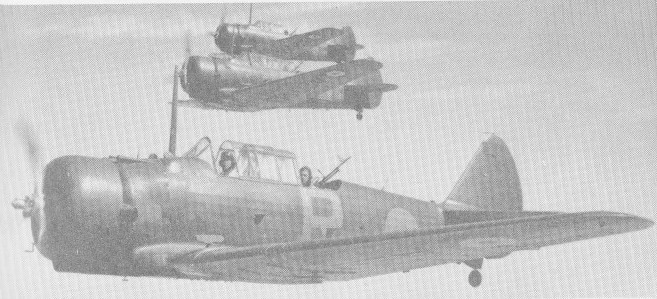
CA-1 Wirraway A20-21, A20-22 and A20-23 of No.21 Sqn
Production of the initial aircraft was handled out of the Commonwealth Aircraft Corporation (CAC) facility at Fisherman’s Bend in Victoria.
CAC designations for Wirraway orders included CA-1, -3, -5, -7, -8, -9, -10 (a bomber version which was cancelled), -10A (dive bomber), and -16. The designation CA-20 covered the conversion of Wirraways for the RAN.
The Wirraway was a low-wing monoplane assemblies with sweep back and curved wingtips, mounted well forward of amidships. Wings were attached to the oblong, rounded airframe. The engine was held in the forward most compartment and was of an air-fed radial type. The cockpit was held aft of the wings with adequate views from under the heavily framed “greenhouse-style canopy. The empennage was conventional and tapered off to form the base of the rounded vertical tail fin. Horizontal tailplanes were situated at the forward base of this single vertical fin. The undercarriage was of the “tail-dragging” arrangement dominated by the two single-wheeled main landing gear legs. While these twin assemblies retracted into the aircraft, the diminutive single-wheeled tail wheel did not and remained exposed whilst the aircraft was in flight. Crew accommodations amounted to two personnel made up of the pilot and an observer.
The Wirraway’s structure comprised a welded chrome-molybdenum steel-tube fuselage with light metal-covered decking and underside, the sides having fabric covered light-alloy frames; a single-spar wing with spaced ribs and metal stressed-skin covering, and fabric-covered dynamically-balanced ailerons and split trailing-edge flaps, and a tail assembly consisting of metal-covered fixed surfaces and fabric covered moveable surfaces.
All fuel was housed in two 46 Imp.gal tanks in the wing centre section. The main undercarriage members were hydraulically operated, retracting into wells forming extensions of the leading-edge roots. The tandem cockpits were enclosed by sliding canopies, full dual controls were installed, the rear seat could be folded and rotated, and a prone bombing position was provided in the floor. Racks beneath the wing centre section could carry 8.5 lb or 11.5 lb bombs and marker flares, and provision was made for mounting two 0.303-in Vickers Mk.V machine guns in the forward upper decking, the pilot being provided with a ring-and-bead sight, and a Vickers Mk.1 0.303-in could be mounted in the rear cockpit.
Early Wirraways were powered by imported Wasp S1H1-G engines, but this engine was subsequently licence-built by CAC (680 single row Wasps eventually being produced), and the three-bladed Curtiss electric controllable pitch airscrews were produced from 1940 by de Havilland Aircraft at Alexandria, NSW.
Top speed was roughly 220 miles per hour with a cruise speed of just 155 miles per hour. Fuel was limited to 116-US gallons in wing fuel tanks with a pair of 11-US gallon reserve fuel tanks. Dimensionally, the aircraft sported a wingspan of 43-feet even with a length of 27 feet, 10 inches. Her height was 8 feet, 8 3/4 inches. When empty, the Wirraway displaced at 3,992 lbs and 6,595lbs for a maximum take-off weight.
The Wirraway was produced in seven major marks beginning with the CA-1. The initial contract called for 40 CA-1 Wirraways (A20-3 to -42) powered by the Wasp R-1340 S1H1-G of 600 hp, and the first aircraft of this contract (A20-3) was flown on 27 March 1939 at Fisherman’s Bend by Flt.Lt. L.H. ‘Boss’ Walker. Production of the initial aircraft was handled out of the Commonwealth Aircraft Corporation (CAC) facility at Fisherman’s Bend in Melbourne, Victoria. The first three RAAF Wirraways were accepted in July 1939. By December 1940, seven aircraft were being delivered weekly, and by September 1941, 45 Wirraways per month were coming off the production line.
The initial contract had been supplemented by the spring of 1940 by orders for 60 CA-3 Wirraways (A20-43 to -102) which differed externally from the CA-1 in having an enlarged oil cooler beneath the engine. The CA-3 was wholly similar to the CA-1, just assigned a different designation due to the nature of the Australian government production contract. This mark numbered 60 examples in all. In fact, the CA-5, CA-7, CA-8 and CA-9 were all also similar in scope to the original CA-1. The CA-5 was produced in a further 32 examples (A20-103 to -143) embodying minor instrumentation and equipment changes.
The CA-7, CA-8 and CA-9 marks were produced in totals numbering 100 (A20-135 to -234), 200 and 188 examples respectively. CA-7 Wirraway production attaining a rate of seven per week by the end of 1940. By this time further orders had been placed with the CAC calling for 200 CA-8 Wirraways (A20-436 to – 635) and 188 CA-9 Wirraways (A20-636 to -823), these each introducing small changes, such a the repositioning of the carburettor air intake, additional wing racks, etc. The CA-10A was an uncompleted bomber proposal, fitted with dive bomber wings but the CA-3, CA-5, CA-7 and CA-9 models were ultimately modified with such wings to become the CA-20 mark. CA-16, the last production Wirraway, was built to the tune of 135 examples before the last rolled off of the Commonwealth assembly lines and these represented the largest modification since the inception of the CA-1.
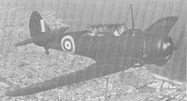
CA-9 A20-622 flown in the summer of 1942
The initial orders for 620 aircraft, production rate attaining 45 aircraft per month in September 1941, and was completed by June 1942, but limited production continued until 1946 when the 755th Wirraway, A20-757, was delivered. The exigencies of the times had resulted in an order for a further 150 Wirraways of the modified CA-16 version (A20-1075 to -1224) intended for the dve-bombing role, although only 135 of these were to be delivered to the RAAF.
Earlier proposals for dive-bombing versins of the Wirraway, the CA-10 and CA-10A, had been cancelled, and the CA-16 differed from the standard Wirraway primarily in making provision for larger external bomb loads, racks being fitted immediately outboard of the wing centre section for two 500 lb and two 250 lb bombs which could be carried in addition to the six 8.5 lb or 11.5 lb anti-personnel bombs and eight target-markers. The 1500 lb increase in offensive load necessitated a conmitant reduction in weight elsewhere, and the twin Vickers guns in the forward fuselage decking and the flexible rear-firing gun were removed, and the aircraft was normally flown as a single-seater when maximum bomb load was carried, although the second seat was retained. The CA-16 fitted a pair of dive brakes for dive bombing sorties. The last was delivered on 30 November 1953.
CA-16
CAC CA-16
Australia maintained the largest collection of Wirraways and these served with the Australian Air Force squadrons No.4, No.5, No.12, No.21, No.22, No.23, No.24 and No.25. The Australian Navy Fleet Air Arm utilized 17 of the type with squadrons No.723 and No.724. The RAN first aircraft was delivered on 24 November 1948. The United Kingdom’s Royal Air Force fielded one squadron (Y Squadron) of Wirraways in Malaya from 1941 to 1942, this being formerly the No.21 Squadron of the RAAF. The United States operated the Wirraway in limited numbers and only for a brief time with its HQ Flight as part of the 5th Air Force.
In 1940-41, camouflaged Wirraways were deployed to forward bases in Malaya (No 21 Squadron) Rabaul (No 24 Squadron), and Darwin (No 12 Squadron). On 6 January 1942, Flight Lieutenant B. Anderson of No 24 Squadron became the first RAAF pilot to engage in air-to-air combat in the South-West Pacific, when his Wirraway intercepted a Kawanishi (Mavis) flying-boat over Rabaul on January 6th, 1942 with no confirmed kill. Two weeks later, on 20 January 1942, the Rabaul Wirraways achieved fame when eight aircraft, including A20-177, piloted by Sergeant W. Hewett, engaged a force of over 100 Japanese fighters and bombers. Although hopelessly outclassed by enemy aircraft, the Wirraway remained in the front line as a stop-gap fighter, and on 26 December 1942, Wirraway history was made when Pilot Officer J. Archer, in A20-103, succeeded in shooting down a Mitsubishi A6M Zero fighter near Gona. Additional actions placed Wirraways over the skies of New Guinea but these were primarily used as ground attack platforms in support of ground forces in the region. The Wirraway continued in this respect until Curtiss P-40 Warhawks could be delivered in sufficient numbers from America and CAC could bring online its “Boomerang” dedicated fighter platform. A Wirraway was used in 1947-48 by No 81 Wing while on duty with the British Commonwealth Occupation Forces in Japan. The total production run was 755 and despite her early-war origins, the Wirraway continued on in the post-war world, primarily back in form with her dedicated trainer roots. The Royal Australian Navy would retire their Wirraways in 1957, replaced by the jet-powered de Havilland Vampires from Britain, while the Royal Australian Air Force continued Wirraway use up until 1958 – her last flight being formally recognized on April 27th, 1959.
After WW2 a number of Wirraways were converted to agricultural use, leading to development of the CA-28 Ceres agricultural aircraft.
CAC CA-16 Wirraway Engine: One 600 hp (448 kW) Pratt & Whitney R-1340-S1H1-G Wasp 9-cylinder radial Weight loaded: 2991 kg / 6,595 lb Propeller: Hamilton Standard Constant Speed, All metal, three blade Fuel: Aviation Gasoline 100 Octane Wing Span: 13.11 m / 43 ft 0 in Wing Area: 255.75 sq. ft / 23.76 sq. m Length: 8.48 m / 27 ft 10 in Height: 2.66 m / 8 ft 8 in Empty weight: 3,992 lb / 1,811 kg Maximum Takeoff weight: 6,595 lb / 2,991 kg Wing Tank Capacity: 97 Imp Gal / 441 Ltr / 116 U.S. Gallons Reserve Tank Capacity (2): 9 Imp Gal / 41 Litres / 11 U.S. Gallons Initial Rate of Climb: 1,950 ft per minute Max. speed: 354 km/h / 220 mph / 191 knots Cruise Speed: 135 knots / 155 mph / 250 km/h Ceiling: 7010 m / 23000 ft Range: 1159 km / 720 miles Armament: 2 x 0.303 Vickers machine guns, 2 x 500 lbs and 2 x 250 lbs if no observer carried Crew 2 Hardpoints: 2
Wirraway 3 Engine: CAC-Pratt & Whitney R-1340-S1H1-G Wasp, 600 hp Wingspan: 43 ft Length: 27 ft 9 in Wing area: 255.75 sq.ft Empty weight: 3980 lb Loaded weight: 6353 lb Max speed: 210 mph Cruise: 186 mph ROC: 1350 fpm Range: 735 mi
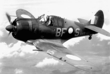
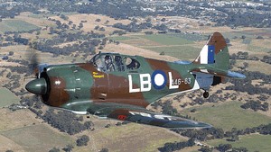
During the war with Japan in 1941 Australia decided to produce an emergency fighter based on the Wirraway trainer. Designed and built in 16 weeks during 1942, the CA-12 prototype used the wings, landing gear, and tail unit of the trainer married to a new fuselage and a more powerful 1,200 hp Pratt & Whitney R-1830-S3C4G Twin Wasp 14 cylinder twin row radial engine from the DC-3.
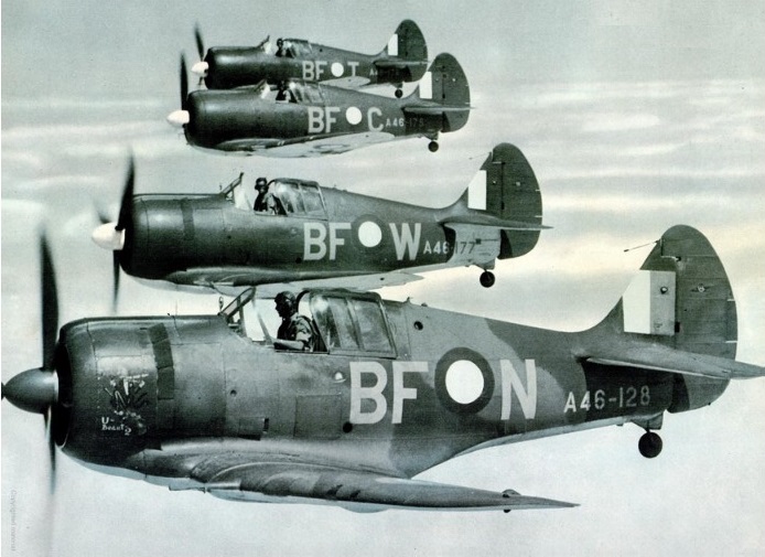
No actual prototype was produced. The first five production aircraft were already under construction before the first aircraft flew on 29 May 1942 (Test pilot Ken Frewin flew A46-1). The first Boomerang Mk 1 fighters entered service in October 1942. Following the flight of the first Boomerang, a further 249 Boomerangs were constructed under four separate contracts between 1942 and 1945. As production progressed, many improvements and modifications were incorporated, and the various standard versions were grouped under three CAC designations: CA-12, CA-13 and CA-19. The last 39 CA-19 Boomerang Mk II were completed as recconnaissance fighters.
CA-12
A high performance prototype, the CA-14 A46-1001 was built with a turbo-supercharger. This same aircraft was later streamlined and fitted with a square-cut tail assembly and became the CA-14A. The RAAF accepted the first Boomerang, A46-1, on 15 July 1942, and the last aircraft, A46-249, was delivered on 1 February 1945. Initial pilot conversion was carried out with No 2 Operational Training Unit at Mildura, and these pilots formed the first operational units, Nos 83, 84 and 85 Squadrons. The first enemy contact was made on 16 May 1943, when Boomerangs from No 84 Squadron intercepted and drove off three Betty bombers. For many months, the Boomerangs successfully carried out many similar sorties until replaced by Kittyhawks and Spitfires. Relegated to the army co-operation role with Nos 4 and 5 Squadron, the Boomerangs soon established a strong reputation for effective strikes throughout New Guinea, the Solomon Islands, and Borneo; particularly so in co-ordinated operations with RNZAF Corsairs. A Boomerang at No 1 Aircraft Performance Unit was modified to take two seats; the second position was placed inside the fuselage behind the pilot and was used by an observer to record instrument and performance data. Altogether, 250 Boomerangs were built and the various versions included 105 CA-12s, (A46-1/105), 95 CA-13s (A46-106/200), 49 CA-19s (A46-201/249), whilst the sole CA-14/CA-14A was numbered in the prototype range as A46-1001.
CAC Boomerang A46-63
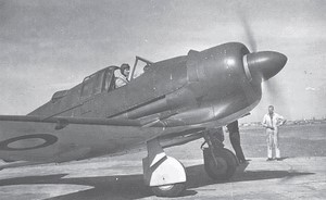
The standard production CA-12/13/19 Boomerang’s Pratt & Whitney R-1830 Twin Wasp power plant was not supercharged sufficiently to permit adequate high-altitude operations. Full-throttle height, in high blower at military power, being only 13,500 feet. To overcome this deficiency, a turbo-supercharger installation was engineered and fitted into A46-1001, the suffix – 1001 allotted to all Australian military prototypes.
Initial layout, under the name, ‘Turbo Boomerang Interceptor’, was shown on a GA drawing dated 8 January 1942, so that early thought was being given to the altitude deficiency inherent in the use of the standard Twin Wasp. A CA-13 airframe was taken off the assembly line at an early stage of production and converted to suit the installation, (attempting to fit the supercharger and ancillaries to a completed aircraft being too demanding).
CA-14
Engineering commenced in July 1942 with Ian Ring, Ian Fleming, and Alan Bolton working on it. Under Tom Air, Bolton was Project Engineer for the design with CSIR doing the research work on the ducting. A mock-up was built in the No.2 Hangar of the Aircraft Factory. A CAC-built R-1830 S1C3G single-stage Twin Wasp on a longer engine mount, with General Electric B2 exhaust driven supercharger and ancillary equipment from a Boeing B-17E, were made available by the USAAF. Their fitment into the aircraft necessitated considerable redesign.
A Harrison intercooler was fitted into the fuselage behind the cockpit, and an intake for engine and intercooler air was positioned on the fuselage port side. Intercooler air was exhausted over the top of the fuselage through a temperature-controlled shutter behind the cockpit. The supercharger was mounted in the starboard fuselage, the normal exhaust tailpipe being extended down the fuselage to feed the turbine. The standard down-draught carburetor air intake was dispensed with giving it a cleaner top cowl line, while high-altitude magnetos were also fitted. A panel of test instruments was mounted in the rear fuselage, with a 35mm remotely-controlled camera to record in-flight data.
As in production of the Boomerang, compromises had to be tolerated, due to lack of optimum equipment. The best propeller available was a three-blade, eleven-foot Curtiss Electric, with a blade activity factor of 87, which limited climb performance and was 50 pounds heavier than that on the standard Boomerang. The B2 supercharger (as the only one obtainable) had a diffuser design which limited critical altitude by 4,000 to 5,000 feet when used with the R-1830 engine, and a further 500 feet in critical altitude was lost because of a 0.50 in-Hg greater pressure drop across the intercooler, compared with an Airesearch cooler which became available after first flights.
Rate of climb was also restricted because of the necessary use of large opening, conventional cowl gills to induce sufficient cooling flow, and resultant large increase in drag.
While the project was being developed, CAC design engineers had the use of the six RAAF Republic P-43 Lancers at Fishermans Bend for study and evaluation, examination of which was of material assistance.
Through October, work progressed and target date for completion was set at the end of the year. Some trouble was experienced with rudder and elevator control-cable runs which had to be duplicated to meet revised AP970 requirements; bends in the system to clear the ducting compounded this modification.
Although Lawrence Wackett requested Air Board approval, on 4 January 1943, for test pilot Jim Carter to be given some flying in an RAAF P-43B Lancer before flying the CA-14, it was advised that there was not one ‘conveniently available’. Instead, Flt Lt John Holden, the RTO at CAC, who had both Lancer and Boomerang experience, was nominated. (six P-43B reconnaissance fighters were allotted for Australian use, as PRU aircraft).
Ian Ring wrote, on 29 November 1986, ‘I was responsible for the turbo-supercharger installation in the CA-14A. I seem to recall seeing an American installation, but I do not remember getting any significant help from it, other than a general picture. Our installation and turbine performance data came from Pratt & Whitney. The problem was mainly one of accommodating the turbine in the appropriate position in the exhaust system, with suitable heat and fire isolation, and designing the inlet manifolds. The result was a spectacular rate of climb.’
The initial CA-14 flight was made on 13 January 1943 by Holden (promoted to Squadron Leader in that period). He not only proved the turbo installation, but also carried out comprehensive performance trials, and was commended by Aircraft-Superintendent Hugh Francis in a letter to Wackett, then in the US.
Even if Carter was to have taken over the further test work, as would have been the norm, it was not to be, as he was killed in the CA-4 Woomera crash on 15 January. Subsequently the new company test pilot, Greg Board, who arrived on 10 March, took over the task, and in the letter to Wackett, Francis told of Board’s appointment, stating that he had so far flown at very high pressure, and had been satisfactory in every way.
Precedence was given to assessing the engine installation and aircraft performance, and, with approximately 17 hours of flying by 29 March, the only other aspects noted were that ground handling, take-off, and the stall, were similar to the Boomerang, with better forward visibility resulting from removal of the carburetor air intake on top of the cowl.
At that time, engine overheating was occurring with the use of continuous climb outlet to 20,000 feet, but it was felt that fan cooling, then being planned, would cure this. Turbine exhaust temperature was at 780C, 35C below the maximum permissible, while turbine cooling and lubrication were satisfactory. Initial intercooling deficiency was overcome by removing the two lower cowl gills on the port side, thereby obviating engine cooling efflux inflow to the intercooler. Ignition breakdown at high altitude was overcome by replacing the Scintilla magnetos with Bosch high-altitude types. Further flights revealed that the aircraft was neutral stable in the lateral plane, directionally unstable, and rudder-trim changes with speed were excessive.
To overcome these latter two faults, the fin area was increased and redesigned, while lateral stability was improved by sweeping the wing tips up, as had been done on the Boomerangs. The supercharger installation was considered to be very satisfactory, but, due to the restricted climb, a cable was sent to Wackett on 15 April recommending that he obtain a four-blade eleven-foot propeller for the aircraft, similar to that fitted to the P-51B.
Performance and handling tests, at which time it was fitted with a large spinner, were completed by CAC (including flying to 35,000 feet) and it was delivered to the RAAF in April. On its return from Laverton in May, a new fin and rudder were fitted to further increase vertical area, and these improved the aircraft’s handling qualities as reported by the company test pilot.
It was returned to the RAAF for further evaluation. Board had flown it to 41,000 feet, its upper limit, and found that controllability was then almost non-existent, and that it fell away out of control very easily, (as was to be expected). From the lessons learnt with the CA-14, the same aircraft was developed into the CA-14A, still as A46-1001. Design calculations showed it to have a better all-round performance than the Thunderbolt and the Spitfire VC, comparative operational ceilings (at which rate of climb falls below 1,000fpm) were 34,400 feet, 32,000 feet, and 29,700 feet respectively. With 30 hours of CAC test flying and ten hours of RAAF evaluation on the CA-14, the conversion was carried out through June and July, with the following changes and new equipment scheduled for incorporation.
1) CAC-built R-2000 Twin Wasp replacing the R-1830. (not achieved.)
2) A B9 turbo-supercharger (actually a B13 was fitted).
3) The four-blade 11 foot Hamilton Standard propeller with blade-activity-factor of 113.5.
4) Ten-bladed cooling fan mounted behind the propeller, and driven through the reduction gearing at three times propeller speed.
5) Sliding cowl gills in place of the conventional hinged type.
6) Retractable tail wheel (not achieved).
7) The intake for the intercooler and engine air was fed from directly behind the fan, gaining considerably from ram effect, and also further increasing critical altitude. The ducting was set nearer the fuselage centre line and did not protrude as far out from the fuselage as it did on the CA-14.
8) The Airesearch intercooler. (40 pounds lighter than the Harrison)
9) A bulkhead in the rear fuselage (not achieved, it is believed, unless the auto observer panel was so described).
10) Changes in the oil-cooler installation and ducting.
With the original hinged gills opened, there was a tremendous increase in drag and buffeting and a reduction in controllability and forward vision. To overcome these liabilities, sliding gills were developed on A46-157 and a variable exit orifice, which was capable of controlling the cooling airflow within laid-down limits, was achieved. Operated hydraulically, as were the standard hinged gills, these slid backwards and forwards along a series of rails to alter the exit.
For some reason, the hinged gills were reinstated at some later stage, and were still on the aircraft when it was eventually broken-up. (It has not been possible to find detail of the changes in item 10, necessary because the exit ducting from the oil-coolers could not be allowed to feed the exhausted air into the extended intercooler/engine intake in the CA-14A, on thermodynamic grounds, and so as not to detract from maximum power).
The first graduate from the Sydney University Aeronautical Engineering Course, completed in 1941, was Alan Bolton, who went straight to CAC on Boomerang stressing, and then worked on the CA-14/14A design – he was able to advise in January 1994 that, to the best of his recollection, the outlet had been relocated to the starboard side into the duct which carried the exhaust tailpipe.
However, it is not known how oil-temperature control was effected in such a position, seemingly without the pilot-controlled exit flap, which had been on the port-side of the CA-14 and all production Boomerangs. During the conversion, a further increase in fin area was added, and the centre-section leading edges were straightened and swept forward, thus cutting out the wheel well fairings. During high-speed dive tests, up to 400 mph IAS, on A46-27, shock waves at the fuselage wheel-well junction occurred at about 360 mph by obviating this junction, wind-tunnel tests, showed the shock waves disappeared unti1 420mph was reached.
A limiting dive speed of 410mph was then placed on the CA-14A. Weight increase with these modifications was 100 pounds, making the all-up weight 8,132 pounds. Wackett wrote to DAP Secretary Letcher on 29 June 1943 to recommend production of the CA-14A before CA-17 manufacture could be started. With almost all of the detail parts for the 200 Boomerangs completed, various departments would be out of work within the next two months, and the assembly task would be completed in October.
With at least six months to the start of detail work on the CA-17, dependent on the arrival of information from the USA, and manufacture of the necessary tooling to begin fabrication, at least 200 more Boomerangs could be built, and such was necessary to keep the organisation intact, pending the start of CA-17 work. As there was need for an urgent decision, for either standard Boomerangs or the CA-14A development, he recommended the latter.
It used fully 75% of the tooling for the standard Boomerang, and it was therefore possible to issue production orders for much of the detail parts immediately, while producing tooling for the new parts necessary to suit the supercharger installation. He summarised the project and company hopes in a report which contained the following key points: The CA-14A’s performance would better the Spitfire Vc:
it is sound reasoning to produce a version which can continue until the CA-17 becomes available;
installation of the CA-14A’s turbo-supercharger has been carried out successfully;
the 2000 cubic inch conversion of the 1830 engine, conducted locally on a Lidcombe built engine, has much promise;
after a long series of trials the 40-degree propeller with wooden blades functions perfectly in flight;
the development of the geared cooling fan is sufficiently advanced to enable this feature to be incorporated in the CA-14A. The success of the Focke Wulf 190 is largely due to this feature;
the CA-14A will incorporate a larger fin and rudder and an improved fairing at the leading edge of the centre section. Both of these features have proved advantageous;
the U.S. Army Air Force in Australia has hundreds of superchargers in store, and it should be possible to make a strong case for favourable consideration that sufficient of these be allotted for CA-14A production.
At the 5 July 1943 meeting of the AAC, Wackett emphasised that it was necessary to give immediate consideration to the production to be carried out between the thencurrent Boomerang contracts and the beginning of the Mustang, re-iterating the points made in his letter to DAP, and pointing out that the CA-14A was definitely the best possible aircraft to build until the CA-17 was under way.
Production of 120 further Boomerangs out of a DAP proposed 325 was recommended by the Minister for Aircraft Production on 8 July, with these to have the R-2000 and turbo-supercharger installed as soon as it could be done. However, the War Cabinet authorised only 50; this was not considered worth the extra effort involved for such a small number, and accordingly the CA-14A proposal was dropped. These 50 were built as standard Boomerangs, under the CA-19 contract. The CA-14A was actually completed and flown on about 26 July with the R-1830 sans fan, and a three-blade Hamilton Standard propeller. The R-2000 engine had suffered from bearing failure on test, and was not ready. Although the necessary enquiries had been made overseas for a suitable four-blade propeller, none was procured in time.
This would have resulted in much greater efficiency at climbing speed at all heights above about 15,000 feet, and at maximum speed. A letter from CSIR to Dept of Air (dated 20 August 1943), stated that the CA-14A incorporated many experimental features, in the design of which the CSIR had been actively concerned, and for this reason the RAAF was requested to carry out further detailed tests beyond the Type Trials.
These were to cover intercooler flows and temperatures, engine cooling, fuel consumption, duct pressures, etc, in order to confirm the theoretical figures arrived at. Gp Capt Walter Armstrong (DTS) answered on 27 August, by saying that, although the CA-14A was of great technical interest, alterations in policy and pressure of other work placed further testing of the aircraft in a low-priority bracket. Turbo-supercharging for fighter aircraft had fallen out of favour here and overseas, mainly because of the slow response to throttle opening, and consequent lack of acceleration during combat.
However, if opportunity occurred, tests on the CA-14A were to continue. Both the CA-14A and A46-157 (and A46-27?) were used by CAC as test beds for the prototypes of a CAC-designed-and-built four-blade propeller with high-density wooden blades, a 38 degrees pitch range and 130 pounds lighter than similar metal propellers. Although developed with some success, and intended for, among others, the Mustang, it did not go into production.
A forced landing was made by A46-157 on 5 November 1943, believed to be due to the loss of about six inches off the tip of a blade, the resultant vibration loosened all but one tailplane attachment bolt before the landing could be effected. Just one week later, the CA-14A made a forced landing at Geelong when a bolt on the spinner backplate fractured.
Both of these aircraft were finally handed over to the RAAF in June 1944, fitted respectively with the first production fan and the first experimental one. The original allotment for the CA-14 project was £15,000 and the actual costs incurred until final delivery totalled £16,418/11/5, the engineering hours expended on it amounting to 15,160. The CA-14A was scrapped at the surplus aircraft park at Laverton during 1947 however, its mainplanes were used by ARL in its structural-fatigue research program.
A Boomerang was modified for use in the Australian film “Smithy” but afterwards was parked in a backyard at Blacktown, NSW, Australia.
Commonwealth CA 12 Boomerang Mk.I Engine: Pratt & Whitney R 1830 S3C4G Twin Wasp, 1184 hp Wingspan: 10.97 m (36 ft 3 in) Length: 7.77 m (25 ft 6 in) Height: 3.5 m (11 ft 6 in) Wing area: 230.35 sqft / 21.4 sq.m Weight empty: 5455.2 lb / 2474.0 kg Max take off weight: 7007.5 lb / 3178.0 kg Max. speed: 256 kts / 474 km/h / 296 mph Cruising speed: 226 kts / 418 km/h Service ceiling: 29019 ft / 8845 m Range at 190mph/304kph: 930 mi / 1490 km Wing load: 30.55 lb/sq.ft / 149.00 kg/sq.m Crew : 1 Armament : 2x MK 20mm, 4x MG 7,7mm
CA-13 Boomerang Mk II Engine: one 1,200-hp (895-kW) Pratt & Whitney R- I 830-S3C4-G Twin Wasp radial piston Propeller: Hamilton Standard 3E50 Constant Speed three-blade Diameter: 11′ 0″ (3.35 m) Fuel: Aviation Gasoline 87 Octane Maximum speed 305 mph (491 km/h; 265kts) at 15,500 ft (4,725 m) Initial climb rate 2,940 ft (896 m) per minute Service ceiling 34,000 ft (10,365 m) Range 1,600 miles (2,575 km) Weight empty 5,373 lb (2,437 kg) Maximum take-off 8,249 lb (3,742 kg). Wing span 36 ft 0 in (10.97 m) Length 25 ft 6 in (7.77 m) Height 9 ft 7 in (2.92 m) Wing area 225.0 sq ft (20.90 sq.m) Armament: Two 20mm Hispano or CAC manufactured cannons, Four 0.303in Browning machine guns Fuel capacity Wing Centre Section (2): 45 Imp Gal / 204 Litres / 54 US Gallons Fuel capacity Fuselage Tank: 70 Imp Gal / 318 Litres / 84 US Gallons Fuel capacity jetisonable: 70 Imperial Gallons (318 Lt) Accommodation: 1
When Japan entered World War II in December 1941, the RAAF did not possess a single fighter aircraft for home defence and, consequently, a decision was hurriedly made to produce a local fighter as a stop-gap measure to meet the threatened Japanese onslaught. Fortunately, the Commonwealth Aircraft Corporation already had plans in hand for an interceptor aircraft, and this promising design was ordered into production on 2 February 1942. Thus, Australia’s first single-seat fighter came from an organisation headed by Lawrence Wackett, who was also responsible for the country’s first indigenous fighter, the two-seat Wackett Warrigal Mk II of 1930.
The Wackett was designed specifically for Australian climate conditions, and has a welded chrome-molybdenum steel-tube framework with fabric covering.
The first of two prototypes powered by the DH Gipsy Six engine was flown early in 1940. Owing to the difficulty of obtaining these engines for production aircraft, the design was modified to take the 165 hp Warner Super Scarab 165D radial engine.
The Wackett designed prototype CA-2 Wackett two-seat prototype went into production designated CA-6. Two hundred were then produced for the RAAF.
CA-6 Wackett Engine: 165 hp Warner Super Scarab 165D Wingspan: 37.01ft (11.28m) Length: 25.98ft (7.92m) Height: 9.84ft (3.00m) Empty Weight: 1,909lbs (866kg) Maximum Take-Off Weight: 2,590lbs (1,175kg) Maximum Speed: 115 mph (185kmh; 100kts) Maximum Range: 425 miles (684km) Accommodation: 2
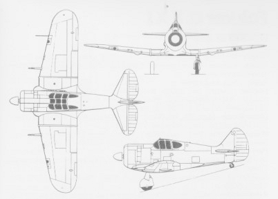
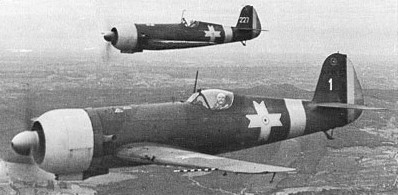
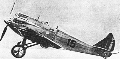
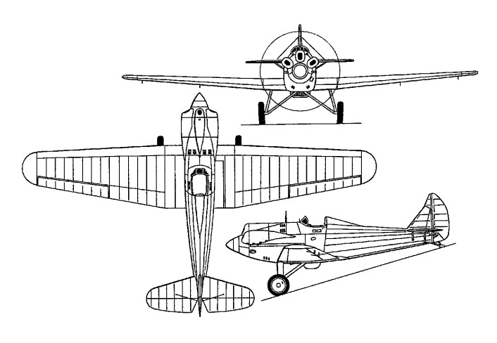
Provisional design work on a monoplane fighter with retractable landing gears was privately started by a small JAR team in early 1936, to be abandoned at the end of the year due to lack of interest shown by authorities. Corrupt members of the Romanian government had already influenced the military to place a substantial order for the ill fated PZL P.11. However, the design was secretly warmed up in mid 1937 and eventually lead the prototype of an aircraft comparable to the main fighter designs of those pre war years. Designed as a successor to the licence-built P.Z.L. P.24E by a team comprising Ion Grosu, Ion Cosereanu, Gheorghe Zotta and Gheorghe Vallner, the I.A.R.80 single-seat fighter was flown on 20 April 1939 in the hands of Capitan Aviator Constantin Pufi Popeseu, IAR’s chief test pilot. The prototype was powered by a 900hp I.A.R.-K 14-II C32 14- cylinder air-cooled radial based on the Gnome-Rhone 14K Mistral-Major and its armament consisted of two wing-mounted 7.92mm FN-Browning guns. The series-production I.A.R.80 appeared in the spring of 1940, and featured a 52cm increase in wing span, a 74cm increase in fuselage length, greater fuel capacity, an aft-sliding cockpit canopy, an armament of four 7.92mm guns and a 930hp I.A.R.-K 14-III C36 engine. The series model also discarded the tailplane bracing struts featured by the prototype. The first flight of an initial series production dive bomber, the IAR 81, No 81, happened on August 16,1941. The I.A.R.80 achieved operational capability on 14 January 1941 with Flotilla 2 Vinatoare of the Royal Air Forces of Romania (Fortelor Aeriene Regal ale Romania), or FARR. The 50th and last of the initial series (No 175) left the production line in April 1942, and was fitted with an extra pair of guns, this six-gun armament being standardised for subsequent aircraft, which were designated I.A.R.80As, these also having racks for two 50kg bombs and being powered by the 1,025hp I.A.R.-K 14-1000A engine. Ninety I.A.R.80As were followed by 50 I.A.R.80Bs, with an armament of four 7.92mm and two 13.2mm guns, the 21st and subsequent aircraft of this batch having a further increase in wing span of 48cm and provision for underwing drop tanks. Manufacture of the pure fighter version of the basic design was completed with 50 I.A.R.80Cs – originally laid down as I.A.R.81Bs, which see – with 20mm Ikaria cannon replacing the 13.2mm weapons and reintroducing the tailplane bracing struts. A small number of I.A.R.80s remained in Romanian service until late 1949, after which survivors with the lowest hours were rebuilt as I.A.R.80DC tandem-seat dual-control advanced trainers. The Junkers Jumo 211Da was not the only in line engine to be experimentally fitted to an IAR 80 airframe. At the end of June 1943, several test flights were performed with an IAR 80 fitted with a Daimler Benz DB 601Aa from a Messerschmitt Bf 109E.
IAR-80 prototype 1939 Engine: 870hp IAR K14-III C32 Wingspan: 10m open cockpit Armament: 2 [or 4?] x FN-Browning 7.92mm
IAR-80 initial production 1941 Engine: 930hp K14-III C36 Wingspan: 10.52m Armament: 4 x 7.92mm 20 built
IAR-80 (No.13) April 1941 Engine: 1100hp DB 601Aa (from Bf-109E) Wingspan: 10.52m
IAR-80 late production 1941 Engine: 960 hp IAR K14-IV C32 Armament: 4 x 7.92mm 30 built
IAR-80A Engine: 1025hp IAR K14-1000A Armament: 6 x FN-Browning 7.92mm reinforced rear fuselage, additional armour protection
IAR-80B Wingspan: 11.00 m / 36 ft 1 in Length: 8.97 m/ 29 ft 5 in Height: 3.52 m / 11 ft 7 in Wing area: 16.50 sq.m / 177.60 sq ft Take-off weight: 2980 kg / 6570 lb Loaded weight: 2200 kg / 4850 lb Max. speed: 550 km/h / 342 mph Range: 730km, drop tank 1030km Armament: 4 x FN-Browning 7.92mm mg + 2 x FN-Browning 13.2mm mg 50 built
IAR-80B (No.326) June 1943 Engine: 1475hp DB-605A for trials
I.A.R.80C Wingspan: 11.00 m / 36 ft 1 in Length: 8.97 m/ 29 ft 5 in Height: 3.52 m / 11 ft 7 in Wing area: 16.50 sq.m / 177.60 sq ft Take-off weight: 2980 kg / 6570 lb Loaded weight: 2200 kg / 4850 lb Max. speed: 550 km/h / 342 mph Armament: 4 x FN-Browning 7.92mm + 2 x 20mm Ikarus 50 built
IAR-80DC Postwar conv. to 2-seat trainer (fuselage fuel tank removed)
IAR-80M 1944-45 conv. to uprate IAR-80 gun armament to IAR-81C standards
IAR-80 one conv. Engine: 1600hp engine [Gnome-Rhône 14R?]
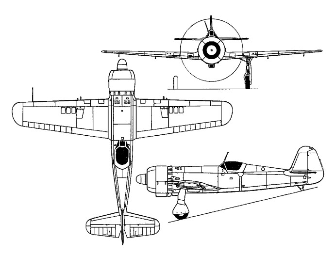
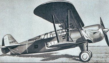
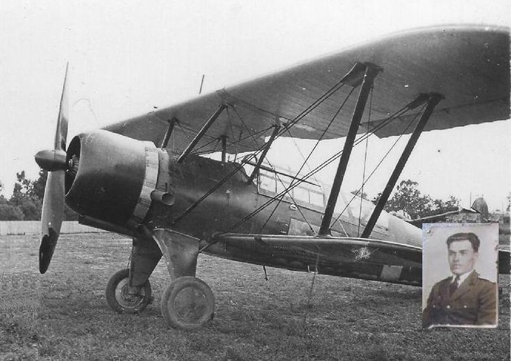
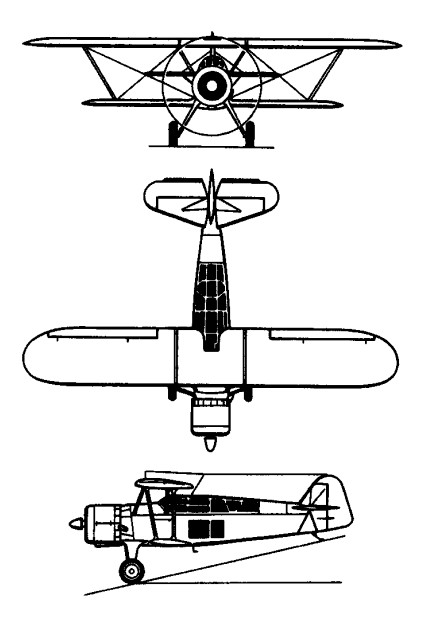
The I.A.R.37 prototype was built to the design of engineers Grossu-Vizuru and Carp. Flown for the first time in 1937 by company pilot Max Manolescu, it was intended to meet an official requirement for a tactical bombing and reconnaissance aircraft. An unequal-span biplane, the I.A.R.37 had fixed main landing gear and was powered by an I.A.R. K.14 radial engine. Its three-man crew was accommodated beneath a continuous glazed canopy, the observer seated between pilot and gunner and provided with full dual controls, a Romanian-designed Estopey bomb-sight, radio and a camera. Defensive armament comprised four machine-guns and the offensive load 12 50kg bombs or six 100kg bombs on underwing racks. The I.A.R.37 entered production.in late 1938 and was built in small numbers before being succeeded in 1939 by the interim I.A.R.38, which differed mainly in its powerplant. An attempt to modify an IAR 37 into a dive bomber was made in the summer of 1940. No 5, redesignated IAR 371, performed the Romanian dive bombing premiere on July 16 with a test diving from 4,000ft (1,200m), piloted by Emil Droc, test pilot of the IAR factory. Several modifications (including the cockpit canopy and fuselage side glazing) were made to the IAR 37 design before it was fitted with a German BMW 132A radial engine, giving birth to the more reliable IAR 38. In January 1939, even before all 50 examples of the –37 had been completed production was shifted in favour of the IAR 38. The last IAR 37, No 47 was first flown on June 16, l939. The final number of IAR 38s actually manufactured is still unclear, the existence of a photograph depicting ‘Red’ 89 suggests that possibly 90, even up to 120, such aircraft could have been finally produced at Brasov. The -38 was soon displaced on the production line by the I.A.R.39. The increased fuel consumption of the more powerful IAR K1 4 engine installed in the IAR 39s decreased the aircraft’s range to 350nm (650km), equal to the similarly equipped IAR 37. Of the total production of 325 I.A.R.37, 38 and 39 aircraft, over 200 were I.A.R.39s, 96 built under sub-contract by the S.E.T. company and over 100 by I.A.R.
IAR 39
By the end of 1940 the I.A.R. biplanes were in large-scale service with Fortelor Aeriene Regal ale Romania (Royal Romanian Air Force) or FARR. They equipped a number of squadrons attached to the various army corps and by June 1941, when Romania supported the German offensive against the Soviet Union, the three reconnaissance flotile of the FARR had 18 eskadrile, 15 of which were equipped with I.A.R. biplanes. In July 1942 the air expeditionary force in the Soviet Union had been re-formed as Corpul I Aerian and had several groups equipped with the I.A.R.39. Eleven reconnaissance eskadrile were operating with the army co-operation flotile during the 1944 offensive in the Ukraine, most of them with I.A.R.39s on strength. Post-war the new Communist republic was declared at the end of 1947, and the reorganised air arm, known as the FR-RPR (Fortele Aeriene ale Republicii Populare Romania) had a small number of I.A.R.39s for training and liaison duties for several years. The last member of the IAR 37/38/39 family was withdrawn from service in mid 1960s.
IAR-38 Engine: BMW 132A, 522 kW (700 hp) Empty weight: 5,070 lb (2,300kg) Taller tail. 75 built (IAR).
IAR-39 Engine: 1 x IAR K.14-IV C32, 16 kW (960 hp) Wingspan: 13.10 m / 42 ft 11.75 in Length: 9.60 m / 31 ft 6 in Height: 3.99 m / 13 ft 1 in Wing Area: 40.30 sq.m / 433.79 sq ft Take-Off Weight: 3085 kg / 6801 lb Loaded Weight: 2177 kg / 4799 lb Max. Speed: 336 km/h / 209 mph / 182 kn Service Ceiling: 8000 m / 26245 ft Range: 1050 km / 652 miles / 567 nmi Armament: 3 x FN (Browning) 7.92mm machine-guns Bombload: 288kg (635lb) or 144 air-grenades Crew: 3 255 built (95 at IAR and 160 at SET).
The Aeronautica Militara selected the P.Z.L. P.11 for the re-equipment of its fighter element in 1934, and a small series of I.A.R.14s was also ordered that year for evaluation purposes. Flown in 1933, the I.A.R.14 was essentially similar to the I.A.R.13, but reverted to the Lorraine 12Eb engine, which had the advantage of being licence-built by I.A.R. The fuselage of the I.A.R.14 was redesigned, the turnover pylon was incorporated in a fairing aft of the cockpit, shorter-span, broad-chord ailerons were introduced, the vertical tail was redesigned and the span of the horizontal surfaces was increased, their inverted Vee type bracing struts giving place to parallel struts. Armament remained a pair of 7.7mm Vickers guns. The last IAR 14 fighter, No 20, manufactured in series at IAR, made its first flight on September 2, 1939, five years after the order was placed by the Romanian government, and was still flown during the war years. The twenty I.A.R.14s delivered to the Aeronautica Militara in 1934 were utilised, after service evaluation, in the fighter training role.
Engine: Lorraine 12Eb Take-off weight: 1540 kg Empty weight: 1150 kg / 2535 lb Wingspan: 11.70 m / 38 ft 5 in Length: 7.32 m / 24 ft 0 in Height: 2.50 m / 8 ft 2 in Wing area: 19.80 sq.m / 213.13 sq ft Max. speed: 294 km/h / 183 mph
In several cases the code name of BH-39 after her designers Benes and Hajn is used for this type.
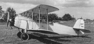
The prototype (designated BH.39NZ) first flew in 1931 with a 120 hp Walter NZ nine-cylinder radial engine. The 1936 next 8 built used 140 hp Walter Gemma radials (designated BH.39G). After this the 160 hp Armstrong Siddeley Genet Major was fitted (designated BH.39AG of 1937).
Praga E-39.21
Praga E-39.21, the 21st production one, was powered by a Walter Gamma engine.
A total of 149 aircraft appears to have been built with 125 used by the Luftwaffe as primary trainers during WW2. No mention of cross bracing while later models had ‘N’ shape interplane struts, cross-braced layout, while the rest on the paint guides had ‘N’ shaped struts.
BH.39NZ Two seat primary trainer Engine: 120 hp Walter NZ
BH.39G Engine: 150 hp Walter Gemma
BH.39AG Engine: 150 hp Armstrong Siddeley Genet Major 1A
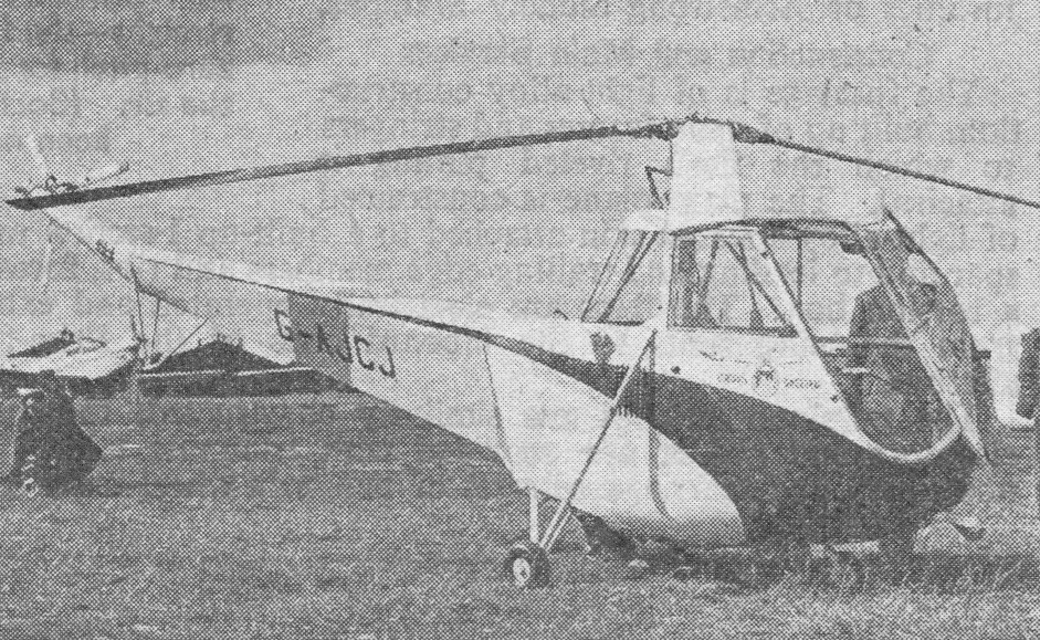
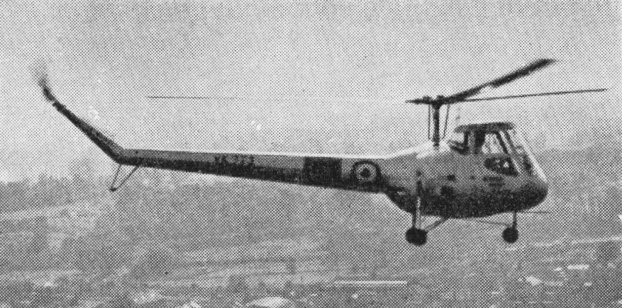
The prototype Skeeter helicopter was designed by the Cievra Autogyro Company as the W14 Skeeter 1 with a 106hp Jameson FF-1 engine and first flew on 8 October 1948 (G-AJCJ), but early development aircraft were under-powered and suffered from resonance problems. The Skeeter had a small, steel tube fuselage structure with a semi-monocoque tail boom section. The three-blade main rotor had metal spars with wooden ribs and a fabric skin, and the two-blade tail rotor was entirely of wood. All the aircraft had tricycle landing gear, although some tests were done with skids.
A second machine, the Skeeter 2 G-ALUF, was flown on October 20th, 1949, in which the most important of several design changes were the employment of a 145hp Gipsy Major 10 engine, increased rotor diameter and a slightly longer tailboom of circular instead of triangular cross-section. Two further-modified Skeeter 3’s were begun by Cierva which were completed by Saro, for evaluation by the Ministry of Supply, after the latter company had acquired Cierva in January 1951. Two Mk. 3 (Gipsy Major 10) and one Mk. 4 (Bombardier 702) were constructed for Ministry of Supply evaluation. The two Mk. 3’s were later fitted with Bombardier engines, and re-designated Mk. 3B. One similar machine was completed as the Skeeter 4.
During 1960 a new skid undercarriage was adopted on the Skeeter for the British Army in place of the wheels previously fitted.
Saro’s two Skeeter 5 prototypes, built as a private venture, was essentially similar apart from instruments and minor controls such as the positioning of the rotor brake, they differed in detail from the prototype Mark 2 Skeeter. The Mark 5 has a 190 b.h.p. Blackburn Cirrus Bombardier 704 engine, while the Mark 3 has a 180 b.h.p. Bombardier 702. The engine is fan cooled with a belt drive. They were the first machines of the series to be really free of the ground resonance problems which had beset the earlier prototypes. In 1956 the Skeeter 5’s were refitted with 200hp Gipsy Major 201’s.
In its civil form, the Skeeter Mark 5 has a 27 gallon fuel tank, which gives an endurance of about three hours, and a further 11 gallons may be carried in an auxiliary tank. The rotor and control system are simple with the three blades being built up on tubular steel spars, with ply ribs and fabric covering. Each blade weighs in the region of 45 lb. The tail rotor of the Mark 3 differed from that of the Mark 5 in having only two blades.
The government-sponsored Skeeter 6 had a 149kW Gipsy Major 30. The power of these engines is much the same but the latter version is a little heavier, carrying more payload and having a higher cruising speed. The Skeeter is built up from four sections the tail cone, complete with rotor, the rear all metal fuselage boom, the centre section, complete with engine, and the cockpit. This seats two side by side with full dual control and instrumenta¬tion.
The Skeeter Mk.6 made overseas appearances at Paris and Stuttgart in June 1956.
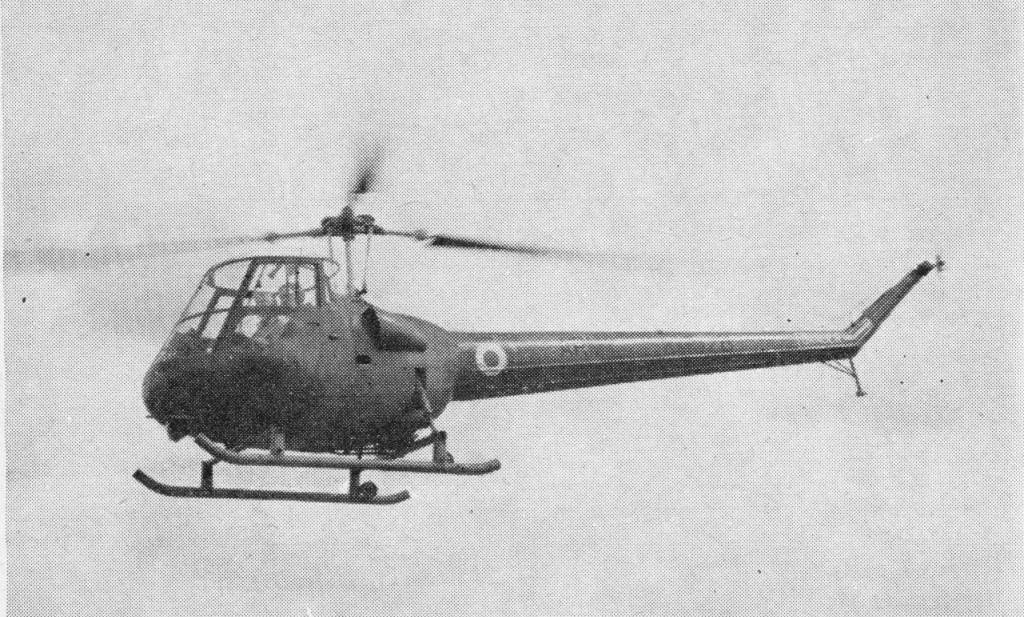
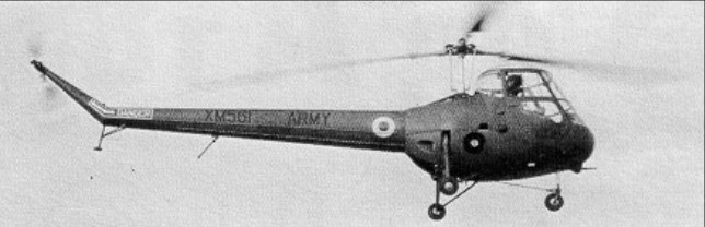
Skeeter Mk.6
After pre-service trials with the Skeeter 6 prototypes, initial production orders were given for two basically similar versions with the Gipsy Major 200 engine. These were the four Skeeter 6A, ordered for the Army Air Corps as the AOP Mk.10, and one Skeeter 6B as the T Mk.11 dual-control trainer for the RAF. Follow-on orders were placed later for the Skeeter 7A (AOP Mk.12) and 7B (T Mk.13), which differed chiefly in having 215hp Gipsy Major 215 engines. The Skeeter 7 was also the subject of a small export order, the Federal German Army and Navy ordering eleven and four as Mk.50 and Mk.51 respectively. Final variant was the Skeeter 8, basically an adaptation of the 7 for commercial operation. Three were built for C. of A. tests, but no civil orders ensued and Skeeter production came to an end in 1960 (by which time Saunders-Roe had become part of the Westland group) after a total of seventy-seven aircraft had been built.
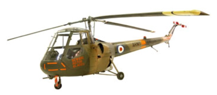
The Skeeter was the first helicopter to enter British Army Air Corps service, replacing fixed-wing Auster aircraft.
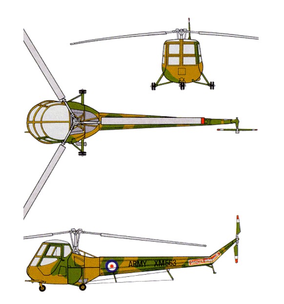
The definitive military version was the AOP12 and deliveries began in June 1958. In the three years this version was in production a total of 64 were built in three separate batches. The Saro Skeeter AOP 12 was a two-seat reconnaissance and artillery-observation-post light helicopter which served with the British Army Air Corps between 1957 and 1967. It was powered by a de Havilland Gipsy Major Type 140 piston engine, delivering 215 bhp at 2850 rpm. It had a cruising speed of 76 knots, a service ceiling of 12800 feet and a range of 160 nautical miles.
In 1957 a small number of Skeeter AOP 10s were delivered to the Army and a T.11 to the RAF and about 50 AOP 12s and T13s were delivered in 1959.
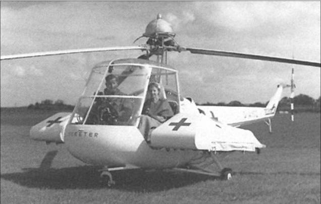
A small number of Skeeters, designated Marks 50 and 51, served in Germany. The German Army and Navy received six and four respectively, which were transferred to the Portuguese Air Force in 1961 but never flown.
Of the fifty or so Skeeters supplied to the British services, the AOP 12’s served mostly at the Army Air Corps Training School, while the RAF T13’s were allocated to the Central Flying School and to No.651 Squadron. Ten of the German Skeeters were handed over in July 1961 to the Forca Aerea Portuguesa, with whom they were still in service in 1968. Dual controls are fitted as standard in all Skeeters. During their early life various Skeeter prototypes were used to flight-test a supercharged Gipsy Major engine, a Blackburn Turmo shaft turbine, and a Napier rocket-powered tip-drive system.
Skeeter with rocket engines at the tip of each blade
With only a single crewman aboard, the Skeeter could be flown in a casualty evacuation role with a stretcher pannier supported on each side of the cabin.
Saunders-Roe Skeeter Mk 6 ambulance (equipped with Napier NRE.19 boost system, rocket-fuel tank above hub)
Most Skeeters were replaced by Scout helicopters in 1967 and 1968 having served with four Army Air Corps Squadrons.
Most Skeeters were replaced by Scout helicopters in 1967 and 1968 having served with four Army Air Corps Squadrons.
Saro Skeeter 6 Engine: Gipsy Major 30, 186 h.p. Rotor diameter: 32 ft Rotors: 3-blade main; 3-blade tail Fuselage length: 28 ft 5 in Loaded weight: 2,200 lb Ceiling: 11,900 ft Typical range: 260 miles at 101 mph Seats: 2
Skeeter 6A / AOP 10 Engine: Gipsy Major 200
Skeeter 6B / Skeeter T Mk.11 Engine: Gipsy Major 200
Saro Skeeter 7A / AOP 12 Engine: de Havilland Gipsy Major Type 140, 215 bhp at 2850 rpm Cruising speed: 76 knots Service ceiling: 12,800 feet Range: 160 nm Seats: 2
Saunders Roe AOP 12 Skeeter Engine : De Havilland Gipsy Major 200 Mk 30, 200 hp Length: (blades folded) 28 ft 5 in Length with rotors turning: 8.66m Fuselage length: 26.509 ft / 8.08 m Rotor diameter: 32 ft / 9.75 m Height: 2.29m Empty weight: 780kg Max take off weight: 2200.6 lb / 998.0 kg Max. speed: 87 kt / 162 km/h Range: 186 nm / 345 km Hovering ceiling, IGE: 1680m Service ceiling: 3900m Crew: 2
7B / T Mk.13 Engine: de Havilland Gipsy Major Type 140, 215 bhp at 2850 rpm
Skeeter 8
Skeeter Mk 50 Main rotor diameter: 9.75m Maximum speed: 267km/h
Skeeter Mk 51 Main rotor diameter: 9.75m Maximum speed: 267km/h