Dassault Mystère I / MD 452 Mystère II / MD.452 Mystère IV

MD 452 Mystère II

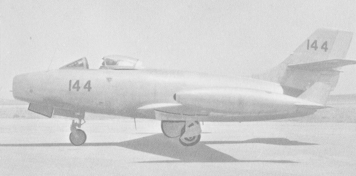
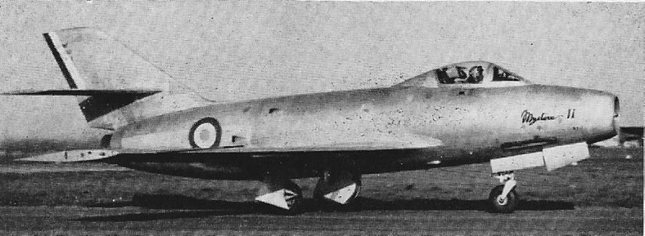
From the Ouragan evolved the swept-wing Mystere I that first flew in February 1951 with a Nene 104B turbojet.
A progressive development of the basic MD.450 Ouragan, the first prototype, the Mystere I, first flew on 23 February 1951. It retained the fuselage, Nene engine and armament of the MD.450, with a new, sweptback (30 deg) wing and redesigned tail surfaces. Wing thickness chord ratio 9%.

Dassault Mystère I / MD 452 Mystère II / MD.452 Mystère IV Article

Three more prototypes followed, differing primarily in power plant, two having the 2850kg Hispano-Suiza Tay 250 and the third having a 2500kg Atar 101C. Eleven (later reduced to 10) pre-series Mystere IIs had been ordered in September 1951, and, of these, the first three and fifth were completed to the Tay-engined IIB standard, the third with twin 30mm cannon. The sixth and subsequent received a similar armament, SNECMA Atar 101C-1, -3, and later D-1 or -2 engine with revised intake trunking and rearranged fuel tanks as Mystere IICs.

The first six of the initial order for 40 was added to the pre-series, the final two of these receiving the afterburning Atar 101F-2 of 3800kg.

Production of an additional 90 Mystere IIC fighters was ordered for the Armee de l’Air, the last flying in January 1957. The series model featured increased tail sweepback, twin 30mm cannon and 2800kg Atar 101D-2 or D-3 turbojet.

Mystere IIC

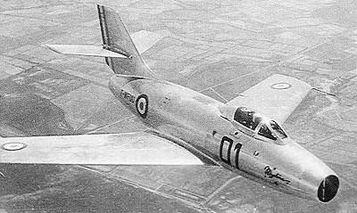
Flown in prototype form for the first time on 28 September 1952, the Mystère IVA was in fact largely funded by the United States, being subject to two large offshore procurement orders covering the manufacture of 325 aircraft in all.

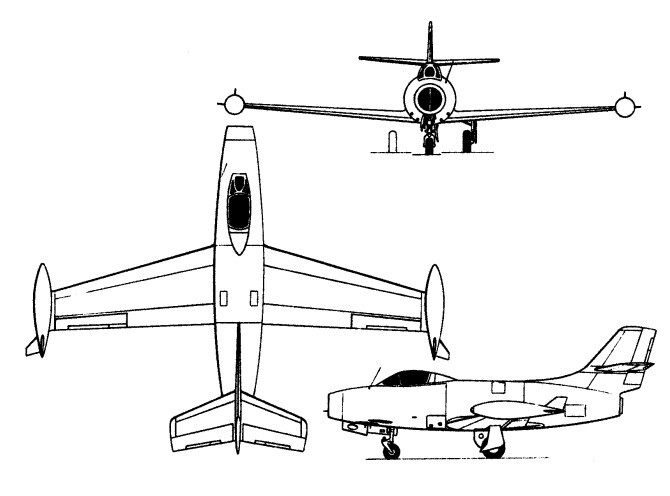
The prototype was powered by a Tay 250A turbojet as used in the Mystere IIA and IIB. The low-mid wings were swept at 40 degrees 57 minutes, and an all-moving tailplane. Wing thickness chord ratio 7.5%. The tricycle undercarriage has single wheels on each unit, the main wheels retracting inwards and the nosewheel retracting forward. Airbrakes are on each side of the rear fuselage.

In the following April, an offshore procurement contract (as part of US support for NATO nations) was placed for 225 Mystere IVAs. This was subsequently supplemented with a contract from the French government for a further 100 aircraft.

Dassault Mystère IVa

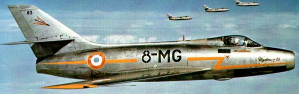
Initial production versions were powered by the Hispano-¬Suiza Tay 250A turbojet engine rated at 2850-kg (6,283-lb) thrust, but this was fairly soon supplanted by the rather more powerful Verdon 350. Differences between the Mystère IIC and Mystère IVA models centred around the wing and fuselage structure, the wing featuring increased sweep and reduced thickness/chord ratio while the fuselage was much more robust. Integral armament consisted of a pair of 30-mm DEFA cannon in the forward fuselage below the cockpit but external ordnance such as 227-kg (500-lb) or 454-kg (1,000-lb) bombs and rocket pods could be car¬ried when the type was operating in the tactical role.

The first series Mystere IVA was flown on 29 May 1954, the initial batch of 50 retaining the Tay 250A engine of the prototype, all subsequent aircraft having the 3500kg Hispano-Suiza Verdon 350 (licence-built Tay). Basic armament comprised two 30-mm cannon.

Mystere IVA

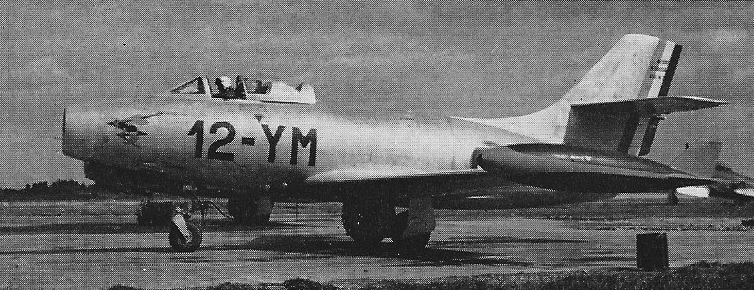
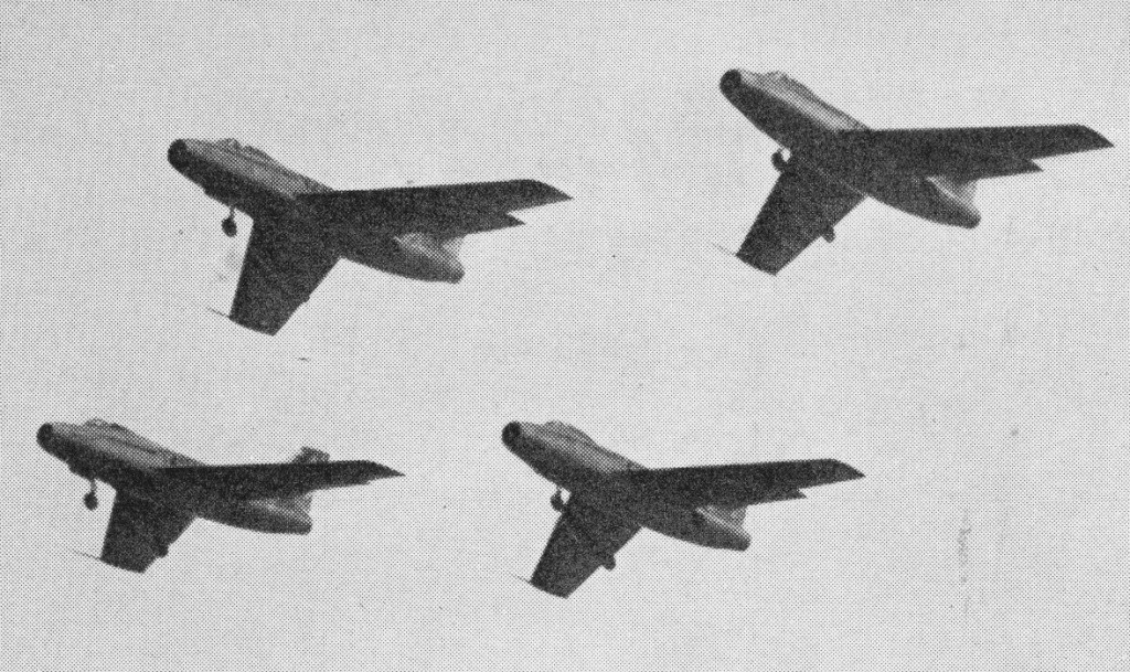
Introduction to the operational in¬ventory came during 1955 when the Mystère IVA began to enter service with the 12e Escadre at Cambrai. However, the advent of the Mirage in the early 1960s resulted in the Mystère IVA being progressively relegated to second-line training duties during that decade.

Of the 275 Verdon-powered Mystere IVAs produced, 60 were supplied to Israel, with deliveries commencing April 1956, and a further contract for 110 was placed by India with deliveries commencing in 1957. The Mystère IVA saw combat action with both of these nations.

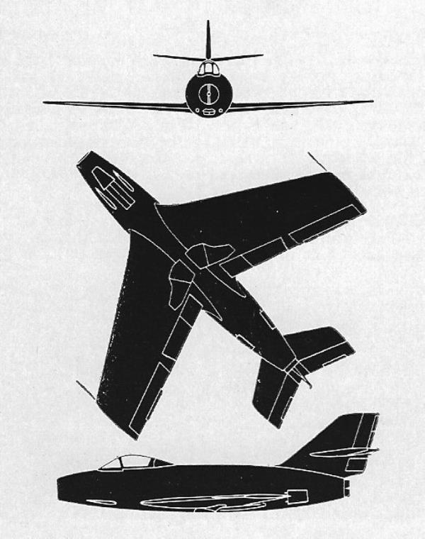
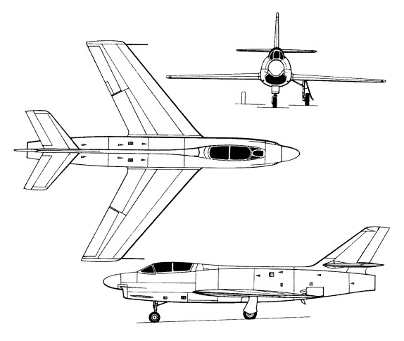
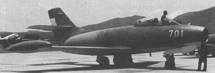
A process of aerodynamic refinement of the Mystere IVA led to the Mystere IVB, which, in fact, shared only wings, horizontal tail surfaces and main undercarriage members with the earlier model. The Mystere IVB was intended for an afterburning SNECMA Atar 101G axial-flow engine in place of the non-afterburning centrifugal- flow Tay or Verdon. It featured an entirely redesigned fuselage of increased fineness ratio, an upper engine air intake lip for the radar ranging aerial in place of the splitter-plate conical body and a lower-mounted horizontal tail. The first prototype was flown on 16 December 1953 with a Rolls-Royce Avon RA 7R engine developing a maximum afterburning thrust of 4330kg. Two additional prototypes followed, the first of these, powered by the Avon RA 7R, flying on 18 June 1954, and the second, with an Atar 101F-12, flying on 31 March 1955. Of seven pre-series Mystere IVBs completed, the first two each had a SEPR 66 bi-fuel rocket motor to augment the thrust of the Atar 101F engine, and the final two had the Atar 101G-2 engine developing an afterburning thrust of 4500kg. The series Mystere IVB was to have been powered by an Atar 101G-31 rated at 4700kg with maximum afterburning, but the programme was cancelled owing to the superior performance potential of the Super-Mystere B2.

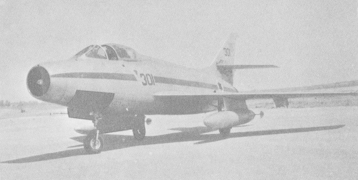
Developed in parallel with the Mystere IVB as a tandem two-seat night and all-weather interceptor, the Mystere IVN differed from the single-seat fighter in several respects. A 1.4m section was added to the forward fuselage to accommodate a second crew member; internal fuel capacity was substantially increased and provision was made for an APG 33 intercept radar with the scanner above the engine air intake. Powered by a Rolls-Royce Avon RA 7R rated at 4330kg with maximum afterburning, the Mystere IVN had provision for an armament of two 30mm cannon and a retractable rocket pack for 52 unguided air-air rockets of 68mm calibre. The sole prototype was flown on 19 July 1954, by which time it had been decided to discontinue the development programme owing to France’s inability to finance the simultaneous development of two night fighters (the other being the Vautour), the insufficient endurance of the Mystere IVN, and the unsuitability of the proposed APG 33 radar.

Having almost completed all Ouragan contracts for the Armde de PAir, for the Indian Air Force (where 71 are in service under the name Toofani), and against off -shore orders, Dassault were beginning to turn out Tay- and Atar-powered Mystere 2s in 1955. These were be followed by the RA.7R-powered Mystere 4B and the 4N. The first prototype 4N was being assembled; it looks much like a Sabre F-86D with two tandem seats and has a single-piece “all-flying” tailplane and full radar interception fire-control.

Total production numbered 421 by the time the assembly line closed in late 1958 and, since they were funded by American money, most of the survivors have been re¬turned to USAF control for disposal.

Gallery

MD 452 Mystère II
Max take-off weight: 7460 kg / 16447 lb
Loaded weight: 5730 kg / 12633 lb
Wingspan: 11.33 m / 37 ft 2 in
Length: 12.24 m / 40 ft 2 in
Height: 4.5 m / 14 ft 9 in
Wing area: 30.28 sq.m / 325.93 sq ft
Max. speed: 1030 km/h / 640 mph

Mystere IIC
Engine: SNECMA Atar 101D-1, 6600 lb
Wingspan: 38 ft 1.5 in
Wing area: 326.15 sq.ft
Length: 38 ft 4 in
Empty weight: 11,511 lb
Loaded weight: 16,442 lb
Max speed: 658 mph at SL / 581 mph at 39,270 ft
ROC: 8460 fpm
Endurance: 1 hr 30 min
Armament: 2 x 30 mm DEFA cannon

Mystere IVA
Engine: 1 x Hispano-Suiza Verdon 350 turbojet, 3500kg / 7,716-lb
Wingspan: 11.12 m / 36 ft 6 in
Length: 12.85 m / 42 ft 2 in
Height: 4.6 m / 15 ft 1 in
Wing area: 32.0 sq.m / 344.44 sq ft
Wheel track: 10 ft 8 in
Max take-off weight: 9500 kg / 20944 lb
Loaded weight: 5870 kg / 12941 lb
Empty weight: 5870 kg / 12,941 lb
Fuel capacity: 572 fal
Drop tank fuel capacity: 275 Gal
Max. speed: 1120 km/h / 696 mph at sea level
Service ceiling: 15000 m / 49200 ft
Initial climb rate: 2700 m / 8,860 ft/min
Range, clean: 915 km / 569 miles
Ferry range: 1690 km / 1,050 miles
Normal endurance: 70 min
Crew: 1
Armament: two 30-mm DEFA cannon
Bombload: two 454-kg (l,000-lb) or four 227-kg (500-lb) bombs, or two pods each containing 3637-mm (1.46-in) rockets.

Mystere IVB
Take-off weight: 8300 kg / 18298 lb
Empty weight: 6170 kg / 13603 lb
Wingspan: 11.12 m / 36 ft 6 in
Length: 13.75 m / 45 ft 1 in
Height: 4.55 m / 14 ft 11 in
Wing area: 32.0 sq.m / 344.44 sq ft
Max. speed: 1180 km/h / 733 mph

MD 452 Mystère IVN
Take-off weight: 10320 kg / 22752 lb
Empty weight: 7140 kg / 15741 lb
Wingspan: 11.12 m / 36 ft 6 in
Length: 14.92 m / 48 ft 11 in
Height: 4.60 m / 15 ft 1 in
Wing area: 32.0 sq.m / 344.44 sq ft
Max. speed: 1030 km/h / 640 mph

Mystere IIC
Dassault Mystere IVA
Dassault Mystere IVN

Dassault MD.450 Ouragan

The MD.450 Ouragan (Hurricane) was designed by engineers Deplant, Cabriere and Rouault as the first fighter developed by Avions Marcel Dassault and the first jet fighter of French design to attain series production.
The Ouragan began full-scale development after the end of World War II, a prototype flying for the first time on 28 February 1949 powered by a 2267kg Rolls-Royce Nene Mk 102. The second and third following on 20 July and 2 June. Twelve (later increased to 14) pre-series aircraft were followed by 350 production Ouragans.

Dassault MD.450 Ouragan Article

The Ouragan has a low wing, swept back at 14 degrees, and slightly swept tail surfaces, with the tailplane mounted part-way up the fin. Conventional ailerons, elevators, rudder, and split flaps are fitted. Airbrakes are on each side of the rear fuselage. A tricycle undercarriage has a single wheel on each unit. The mains retracting inwards into the fuselage, and nose wheel retracts forward.

Of the production Ouragans, the first 50 were completed to an interim standard as MD.450As, subsequent aircraft embodying modifications and equipment changes as MD.450Bs. Changes included replacement of the Nene 102 by the lighter Nene 104B of 2300kg. Armament was four 20mm cannon which could be augmented by 16 Matra T-10 rockets externally.

The 352 produced for the Armêe de l’Air, mainly serving as a fighter-bomber, were superceeded by the Dassault Mystêre IVA in the later 1950s.

An Indian Air Force order for 71 MD.450Bs was placed on 25 July 1953, these having the Nene 105A of 2350kg and British Mk V versions of the French 20mm Hispano-Suiza cannon. Named Toofani in Indian service (the Hindi equivalent of Ouragan), the Dassault fighter remained in first-line use until 1967, a further 33 having been procured from the Armee de l’Air (including 20 unused machines from storage) in March 1957.

Twenty-four MD.450BS were ordered by Israel in January 1955, these being supplied from Armee de l’Air stocks in the following October-November and a further 46 (including one MD.450A) being delivered subsequently. Eighteen ex-Israeli Ouragans were delivered to El Salvador in 1975, remaining in service into the late 1980s.

Engine: 1 x Hispano-built Rolls-Royce Nene Mk104B turbojet, 2270kg / 5,000-lb
Wingspan: 13.16 m / 43 ft 2 in
Length: 10.74 m / 35 ft 3 in
Height: 4.14 m / 13 ft 7 in
Wing area: 23.8 sq. m / 256.18 sq ft
Max take-off weight: 7900 kg / 17417 lb
Empty weight: 4140 kg / 9127 lb
Max. speed: 940 km/h / 584 mph at SL
Initial climb rate: 2400 m (7,874 ft) /min
Ceiling: 13000 m / 42650 ft
Absolute ceiling: 49,213 ft
Range w/max.fuel: 920 km / 572 miles
Endurance: 72 min
Armament: 4 x Hispano 404 20mm canon
Hardpoint capacity: 2 x 434kg
Seats: 1

Toofan
Engine: 5070 lb Hispano-Suiza Nene 105
Wingspan: 40 ft 3.5 in
Length: 35 ft 2.25 in
Height: 13 ft
Wing area: 256.18 sq.ft
Armament: 4 x 20 mm Hispano 404 model 50 canon
Seats: 1
Bombload: 2 x 1100 lb

Dassault MD.303 / MD.311 / MD.312 / MD.315 / MD.316 Flamant

MD.315

The Dassault M.D.315 Flamant (Flamingo) utility transport and aircrew trainer prototype made its maiden flight on 10 February 1947. Engines were two 580 hp SNECMA 12S 201 inverted V 12 air¬cooled, previously known as the Renault 12S and before that the German Argus As 410. This had the designation M.D.303, and was evaluated successfully at the Centre d’Essais en Vol at Bretigny later that year.

Production Flamants, the first of which was flown in January 1949, were intended for service with the Armee de I’Air in France’s overseas territories, and deliveries to AOF (Afrique Occidentale Francaise) squadrons began in October 1950.

Dassault Flamant Article

The Flamant was produced in three main versions, the first, the M.D.311, was a bombing, navigation and photography trainer of which 39 were built.

MD.311

The six-seat M.D.312 military liaison/communications aircraft (142 built) and the 10-seat M.D.315 light utility transport (137 built), were used over a long period by the Armee de I’Air and, in the case of the M.D.312, by the Aeronavale. The production continued 1949 52.

The first production version was the MD.315 Flamant with a crew of two and up to ten passengers or a tonne of freight. The MD.312 was furnished for only six VIP passengers and the MD.311 was a crew trainer, with glazed nose for visual bombing. Most Flamants could be equipped as casevac stretcher (litter) ambulances.

Over 200 were still in service in the mid-1960s, a few were still in use in 1978, though retired by the French armed forces by the 1990s.

Convertible from passenger to cargo or aero-medical transport, several were passed on to other air forces such as those of Cambodia, Madagascar, Tunisia and Vietnam, as they were withdrawn from French service.

One M.D.315 was converted as the M.D.316, with 611kW SNECMA 14X Super Mars radial engines, first flying on 17 July 1952.

MD.316 number 2

A single-finned second prototype, the M.D.316T, had 597kW Wright R-1300-CB7A1 Cyclone radials. These were intended for crew training and commercial transport operation, but neither entered production.

Dassault MD.311 Flamant

Gallery

Avions Marcel Dassault MD 315 Flamant
Engines: 2 x SNECMA-Renault 12S 02-201 inline, 433kW / 572 hp
Wingspan: 20.7 m / 67 ft 11 in
Length: 12.6 m / 41 ft 4 in
Height: 4.5 m / 14 ft 9 in
Wing area: 47.2 sq.m / 508.06 sq ft
Max take-off weight: 5800 kg / 12787 lb
Empty weight: 4250 kg / 9370 lb
Max. speed: 380 km/h / 236 mph
Cruise speed: 300 km/h / 186 mph
ROC: 984 fpm
Service ceiling: 8000 m / 26250 ft
Range: 656 nm / 1215 km / 755 miles
Crew: 2+10
137 built

MD.316T
Engines: 2 x Wight R-1300 Cyclone C7BA1, 800 hp
Max speed: 255 mph at 7218 ft
Cruise: 243 mph
ROC: 1181 fpm
Empty weight: 12,566 lb
Loaded weight: 16,755 lb
Wingspan: 66 ft 11 in
Length: 51 ft 8 in
Height: 21 ft 4 in

MD.315

DAR DAR-10F

The DAR 10F was the only Bulgarian designed military aircraft to have seen service. It was a trim but conservative light bomber with an 840/960 hp Fiat A74RC38 radial, and with spatted wheels and a crew of two under a glasshouse canopy.
The gun armament was heavy: two 20 mm (0.79 in) MG FF cannon in the wings and two 7.92 mm (0.312 in) MG 17 in the top decking, all firing ahead, and an MG 15 in the rear cockpit. In spite of this the 10F could still carry up to 500 kg (1102 lb) of bombs. Darjaviia Aeroplanna Rabotilnitza flew the prototype in 1941 and a small but unknown number entered Bulgarian service.

Span: 12.65 m (41 ft 6 in)
Length: 9.83 m (32 ft 3 in)
Gross weight: 3420 kg (7540 lb)
Maximum speed: 454 km/h (282 mph)

Curtiss-Wright CW-25 / AT-9 Fledgling / Jeep

With the introduction of new high-performance twin-engine aircraft at the U.S. Army Air Corps at the start of the Second World War in Europe it was evident that new aircraft types would be needed for advanced training of future pilots. The gap between the T-6 and types like the B-25 and B-26 bombers had to be closed with a flying course on a twin-engine trainer. Also for the new Lockheed P-38 twin-engine fighter an advanced training course on a twin-engine type was considered as necessary. Beech and Cessna already had their AT-11 Kansas and AT-17 Bobcat twin-engine trainers, but these were more suitable for crew training.

At Curtiss the design and development was started on a twin-engine advanced trainer strictly for pilot training with two-seat capacity for instructor and pilot student which had the take-off and landing characteristics of a light bomber aircraft.

Owing much of its low-wing cantilever monoplane design to the earlier CW-19 trainer, the AT-9 was a relatively small twin-engine low-wing monoplane fitted with two radial air-cooled engines. It only had capacity for two seats; entrance was on both sides with a car-type door. The main wheels retracted partially backwards into the engine nacelles and the tail wheel was non-retractable. The CW-25 was powered by two Lycoming R-680-9 radial engines.

The single CW-25 prototype acquired for evaluation was built with a welded steel-tube fuselage covered with fabric. Also wing and tail planes were fabric covered. The production AT-6 was planned to be manufactured from aluminum with a modern monocoque construction and stressed-skin wings.

Prototype

The prototype AT-9 first flew in 1941 and evaluation proving satisfactory, the type was ordered into production under the designation AT-9, officially named the Fledgling, the AT-9 was almost universally known as the Jeep. The production examples differing from the prototype by being of all-metal construction.

A total of 491 AT-9s was produced and these were followed into service by 300 generally similar AT-9A aircraft. They remained in use for a comparatively short time, for the USA’s involvement in World War II in late 1941 resulted in the early development of far more effective training aircraft.

Designated at Curtiss-Wright as CW-25, the new advanced trainer received the military type designation AT-9. Initially it was named the ‘Fledgling’ but it became much more known by its later name the ‘Jeep’. The flight characteristics of the new trainer were purposely made more demanding for the student pilot. Basically it was the intention that future P-38 pilots would made their first solo flight on this fighter after a 70 hours transition training on the AT-9.

When the test flying of the CW-25 was successfully completed in 1941 the Army Air Corps ordered in total 492 AT-9 production models.

Later a final order was placed for 300 additional slightly improved AT-9A models. Main difference was a later model Lycoming R-680-13 engine with slightly more power output (300 hp), and the undercarriage retraction hydraulics were revised and improved.

The AT-9 and AT-9A was produced at Curtiss between 1941 and 1943; production of the last AT-9A was completed in February 1943. The unit costs of the AT-6 model was U.S. $44,965. The unit costs of the AT-6A dropped to U.S. $ 40,286.

Production totals:
CW-25 prototype:
1

AT-9:
41-5754 to 41-5894 (150)
41-11931 to 41-12271 (341)

AT-9A: 42-56853 to 42-57152 (300)

Total: 792 including prototype

The AT-9 and the later AT-9A was assigned from 1942 on to various military flying schools. Although it was quite demanding to fly, it was fully aerobatic and much more maneuverable that the other twin-engine advanced trainers like the AT-11 and AT-17. In spite of this, there were continuous maintenance problems and because of its more difficult flying properties it had a quite high accident rate.

Formation of AT-9 coded ‘CO’ coded based at the Advanced Twin Engine Flying School at Columbus Mississippi. This flying school had some forty AT-9’s on its inventory

Since the AT-9 could not be used for crew training its operational use was in most cases restricted to P-38 training. By the end of 1943 most AT-9’s were removed from flying status.

Since it was only a two-seater it was hardly used as a civil plane after the war when many aircraft were offered as surplus. Some were used after the war as instructional airframes at technical schools.

AT-9’s at Tulsa, Oklahoma, 18 May 1953.

The U.S.A.F. Museum at Dayton Ohio has an AT-9 on display carrying the serial number 41-12150 and field registration ‘909’. It was completely restored for static display inside the museum. The Pima Air & Space Museum in Arizona has a recovered and incomplete AT-9A wreckage (serial no. 42-56882) for future restoration.

Gallery

Curtiss AT 9 Fledgling
Engine: 2 x Lycoming R-680-9 radial, 295 hp (220 kW)
Wingspan: 12.29 m / 40 ft 4 in
Length: 9.65 m / 31 ft 8 in
Height: 3.00 m / 9 ft 10 in
Wing area: 21.65 sq.m / 233.04 sq ft
Wing loading: 25.83 lb/sq.ft / 126.0 kg/sq.m
Max take-off weight: 2722 kg / 6001 lb
Empty weight: 2087 kg / 4601 lb
Max. speed: 171 kts / 317 km/h / 197 mph
Cruise speed: 152 kts / 282 km/h / 175 mph
Range: 652 nm / 1207 km / 750 miles
Service ceiling: 5,791 m / 19,000 ft
Climb to 3,050 m (10,000 ft): 8.6 min
Crew: 2

Curtiss-Wright CW-22 / SNC-1 Falcon

SNC

Two CW-19 company demonstrators were built, c/n 19R-10 (N16417) in January 1937 and A19R-14 (NC16421) also in 1937. N16417 was later converted to CW-22 specifications and sold in May 1940.
This aeroplane was developed within the context of the US Navy’s enormous increase in pilot training during 1940, and an advanced combat trainer evolved from the CW-19 light fighter and trainer project with features such as retractable landing gear from the CW-21 Demon export fighter. The CW-22 prototype resembled the CW-21 with a longer, two-seat fuselage but considerably lower power in the form of the 313-kW (420-hp) Wright R-975 Whirlwind radial.

The landing gear had main units retracting rearward into underwing fairings as on the CW-21 single-seat interceptor. Powered by a 313kW Wright R-975 Whirlwind radial, 36 CW-22s were exported to the Netherlands East Indies, but due to the Japanese advance in that region were delivered to the Dutch in northern Australia during March 1942.

A developed CW-22B version was sold to Turkey (50); the Netherlands East Indies (25); and various Latin American countries (totalling about 25). Several Dutch aircraft were later captured and flown by the Japanese. Both the CW-22 and CW-22B were armed with two machine-guns, one fixed and the other flexibly mounted.
After a demonstrator had been tested by the US Navy, a CW-22N advanced training version went into production. The US Navy applied the designation SNC-1 Falcon to the type, a total of 455 being purchased in three batches of 150, 150 and 155 respectively; the aircraft of the third batch had a modified, higher cockpit canopy. The initial order for 150 aircraft was later bolstered by five impressed aircraft. Many SNC-1s were sold to private owners in the USA after World War II.

CW-22

Some 136 CW-22s were exported.

CW-22 / SNC-1
Engine: one Wright R-975-28 Whirlwind radial, 420 hp (313 kW)
Wingspan: 10.67 m / 35 ft 0 in
Length: 8.23 m / 27 ft 0 in
Height: 3.02 m / 9 ft 11 in
Wing area: 16.14 sq.m / 173.73 sq ft
Max take-off weight: 1718 kg / 3788 lb
Loaded weight: 1241 kg / 2736 lb
Max. speed: 319 km/h / 198 mph at SL
Cruise: 195 mph at 2500 ft
Service ceiling: 6645 m / 21800 ft
Operational range: 1255 km / 780 miles
Armament: 2 x 7.62mm machine-guns
Crew: 2

Curtiss-Wright CW-21 Demon

In 1938, chief engineer Willis Wells of the St Louis Airplane Division of the Curtiss-Wright Corporation began the development of a single-seat fighter based on the A-19R tandem two-seat military basic trainer. Designated CW-21, it had a Wright R-1820-G5 Cyclone nine-cylinder radial engine rated of 1,000hp for take-off and 850hp at 1830m, and an all-metal stressed-skin structure with a semi-monocoque fuselage. The mainwheels retracted into clamshell-type underwing fairings and armament was two synchronised 12.7mm machine guns.
The prototype CW-21 was flown on 22 September 1938, and shipped to China for demonstration. The prototype was purchased by the Chinese government and a contract placed for three production aircraft and 27 sets of components for assembly by CAMCO. The first production CW-21 was flown on 20 March 1940, and provision was made to increase the armament with a pair of 7.62mm weapons. All three CW-21s built by the parent company were lost as a result of engine failures after taking-off from Lashio while being ferried to Kunming. Assembly of CW-21s by CAMCO at Loi-wing had reached an advanced stage when it was decided to evacuate and, on 1 May 1942, burn the factory to avoid its capture by Japanese forces, the partly-assembled fighters also being destroyed.
In April 1939, Curtiss-Wright’s St Louis Airplane Division flew the prototype of the CW-23 basic combat trainer which was essentially a tandem two-seat, lower-powered derivative of the CW-21 single-seat fighter. It introduced inward-retracting, fully-enclosed main undercarriage members and hydraulically-actuated rather than manually-operated flaps, and these features were adopted for a new version of the single-seat fighter, the CW-21B. On 17 April 1940, the Dutch government signed a contract for 24 CW-21B fighters (of which there was no prototype) and the first of these was flown the following mid-September. The CW-21B retained the R-1820-G5 Cyclone of the earlier CW-21 and armament comprised two 7.62mm Colt machine guns mounted in the forward fuselage. The CW-21B fighters were shipped to Java during October-December 1940, entering service with the MLKNIL. Their light structure and lack of fuel tank protection was to render them particularly vulnerable when committed to operations against Japanese forces in the early months of 1942, the last combat mission being flown by a CW-21B on 5 March.

Curtiss-Wright CW 21 Demon
Engine: Wright R 1820-G5, 986 hp
Length: 27.165 ft / 8.28 m
Height: 8.924 ft / 2.72 m
Wingspan: 35 ft 0 in / 10.67 m
Wing area: 174.269 sqft / 16.19 sq.m
Max take off weight: 4500.4 lb / 2041.0 kg
Weight empty: 3382.5 lb / 1534.0 kg
Max. speed: 274 kts / 507 km/h
Cruising speed: 245 kts / 454 km/h
Service ceiling: 34301 ft / 10455 m
Wing load: 25.83 lb/sq.ft / 126.0 kg/sq.m
Range: 548 nm / 1014 km
Crew: 1
Armament: 2x cal.30 MG (7,62mm), 2x cal.50 MG (12,7mm)

Curtiss-Wright CW-20 / C-46 Commando / C-55 / C-113 / R5C

The 1937 design specifications called for the Commando to feature a pressurized cabin for up to 36 combat-ready troops, longer range than anything available to the USAAF and an above average cruising speed. Design headed by George Page the CW-20 first appeared in prototype form on 26 March of 1940 as the twin-rudder CW-20T.

Curtiss-Wright CW-20 Mock-up of twin-tail prototype at 1939 NYC World’s Fair

Because the US Army was impressed with its possibilities, authorisation was obtained for the purchase of a large number as cargo transports. In the meantime the prototype was bought, modified and given the Army designation C-55. It was later re-converted for civil use and sold to the British government.

The 1941 C-55 (Model CW-20A) was a single-tail prototype Curtiss-Wright CW-20T for evaluation as a USAAF transport, rejected in favour of the C-46. A projected name of Skytruck was not officially assigned. Costing $363,600, the one built 41-21041, later went as Lend-Lease to England and BOAC as G-AGDI.

Curtiss C-55 (41-21041)

The CW-20T prototype later evolved into the CW-20A that featured a revised tail in the form of the more recognizable single rudder assembly. Later development focused in on the requirements as put forth by the United States Army Air Corps which put the CW-20A under trials and consequently ordered a production version of the model designated CW-20B. The main compartment of the C-46 could accommodate (in addition to general cargo) 40 fully equipped troops, up to 33 stretchers, five Wright R-3350 engines or their equivalent weight of other goods.

Curtiss C-46A 41-5159

The 1942 Army production model of the CW-20B, designated C-46A, was a redesign not only to suit it to the duties of a military cargo or task-force aircraft but to allow easy large-scale production. It was produced in three large manufacturing plants and was put into widespread use by the US Army Air Transport Command, Air Service Command and Troop Carrier Command, and by the US Naval Air Transport Command and Marine Corps. Two were built by Higgins Industries (boat manufacturer), New Orleans LA. Final trial models were provisioned to fit up to 45 combat-ready troops and fitted with two Pratt & Whitney R-2800-51 radial engines, a large cargo door and folding wall seats. The C-46 entered service with the plain designation of simply C-46 in the Pacific Theatre – and used almost exclusively there up until about March of 1945, to which the Commando would be seen across the European Theatre as well.

The United States Navy utilized a designation of R5C-1 for their own Commando version, transferred from USAAF inventory, with 120 models of the R5C-1 (39492-39611) going to the United States Marine Corps. Ten of these went to the USCG with long-range fuselage fuel tanks used as cargo and personnel haulers until 1950.

Curtiss XC-46B 43-46963

The 1944 C-46D, TC-46D (Model CW-20B-2) troop transport had a revised nose and double loading doors. An unknown number were modified as TC-46D trainers.

Curtiss C-46D with single door 44-77984

The 1944 C-46E (Model CW-20B-3) were C-46A airframes with stepped windshield and single cargo door. Seventeen were built (43-47403/47419).

Curtiss C-46E
Curtiss C-46E Glider tug (43-47404)

In 1944 Curtiss prepared designs and a mock-up of a commercial version of the aircraft for immediate post-war production. Curtiss-Wright hoped to market it as a 36 passenger civil version of the C-46E, with two 2500hp (1860 kW) Wright C18-B2 engines. Although a total of 26 were on order at one time the CW-20E never really had a chance as a new-production post-war airliner.

Curtiss C-46E Post-war civil (N30019)

The 1945 C-46F (Model CW-20B-4) had engine modifications, squared wingtips, and cargo doors on both sides. 234 were built (44-78545/78778).

Curtiss C-46F (44-78774)

To give the C-46s added performance, some C 46Fs were fitted with two Turbomeca Palas turbojets in underwing pods to operate in Brazil (from 1953). Other aircraft were fitted with more powerful engines as ‘Super C 46s’.

The 1945 C-46G (Model CW-20B-5) was powered by two 2100hp R-2800-34W and featured a stepped windshield. The one built was originally scheduled as a C-46C (44-78945), and later converted to XC-113.

Built in 1945, the sole C-113 (Model CW-20G) 44-78945 was a C-46G with a four-blade General Electric TG-100 turboprop installed in the right nacelle for tests, retaining its original three-blade Wright R-2800-34W on the left. This proved to be an unmanageable arrangement and the ship was damaged in ground runs and never flew.

Curtiss XC-113 44-78945

Planned modifications for double tailwheels and R-3350-BD engines, the C-46H, XC-46K (Model CW-20E-2) was cancelled by the Armistice, although a few other post-war C-46 mods were labelled as C-46H.

The three 1945 XC-46L (Model CW-20H) conversions were test-beds for 2500hp Wright R-3350-BD Double Cyclones.

In October 1954, Terneo Aircraft Corp. announced a contract to overhaul 87 of’ them. The U.S.A.F. still had some of these veteran wartime passenger-freighter in 1955.

In total, US forces accepted 3144, and the C-46 was officially retired from service in 1968, replaced by the C-130 series of transports.

Curtiss C-46A Commando, S/N 42-3649, for sale at Cal-Aero Field, California, post-WWII

Riddle Airlines produced a modification kit in the mid-1950s which added 40mph (64kmh) to cruising speed and 2,204 lb (1,000 kg) to the payload. The improved model was designated C-46R, and Riddle subsequently converted its own fleet of 32 to have 2,100 hp Pratt & Whitney engines.

Curtiss-Wright CW-20T Article

Gallery

C-46 Commando / CW-20B / R5C
1941
Engines: 2 x P&W R-2800-43, 2000hp
Wingspan: 108 ft 1 in
Length: 76 ft 4 in
Useful load: 23,600 lb
Max speed: 269 mpg
Cruise speed: 183 mph
Range: 1200 mi
Ceiling: 27,600 ft
Number built: 25 (41-5159/5183)
Capacity: 50 troop
Cost: $341,831

CW-20B / C-46A Commando
1942
Engines: 2 x Pratt & Whitney R-2800-51 Double Wasp, 2,000hp
Length: 76.44ft (23.3m)
Wing span: 78.54ft (23.94m)
Height: 21.75ft (6.63m)
Empty Weight: 30,001lbs (13,608kg)
Maximum Take-Off Weight: 55,997lbs (25,400kg)
Maximum Speed: 269mph (433kmh; 234kts)
Maximum Range: 1,199miles (1,930km)
Service Ceiling: 27,559ft (8,400m)
Crew: 4
Number built: 1,491 (41-5184/5204, -12280/12433, -24640/24775, 42-3564/3683, -60942/61091, -96529/96707, -96708/96828, -101036/101235, -107280/107399, 43-43339/43340, -46953/47402, 44-77444, -77446)
Cost: $314,700 (>$354,714), $259,268 (>$271,127) in 1943

CW-20B-1 / XC-46B
1944
Stepped windshield.
Engines: 2 x R-2800-34W, 2100hp
Number built: 1 modified from C-46A (43-46963)

C-46C
Prototype built as C-46G instead.

CW-20B-2 / C-46D Commando / TC-46D
1944
Engine: 2 x Pratt & Whitney R-2800-51 Double Wasp, 1973 hp, 1495kW
Wingspan: 32.9 m / 107 ft 11 in
Length: 23.3 m / 76 ft 5 in
Height: 6.6 m / 21 ft 8 in
Wing area: 1359.924 sqft / 126.340 sq.m
Max take off weight: 56009.2 lb / 25401.0 kg
Weight empty: 32404.7 lb / 14696.0 kg
Max. speed: 234 kts / 433 km/h
Cruising speed: 159 kts / 295 km/h
Service ceiling: 27592 ft / 8410 m
Wing load: 41.21 lb/sq.ft / 201.0 kg/sq.m
Range: 1043 nm / 1931 km
Range w/max.fuel: 2770 km / 1721 miles
Crew: 3
Payload: 54pax
Cost: $233,377
Number built: 1,410 (44-77295/77443, -77445, -77447/78544)

CW-20B-3 / C-46E
1944
Number built: 17 (43-47403/47419)

CW-20B-4 / C-46F
1945
Cost: $221,550
Number built: 234 (44-78545/78778)

CW-20B-5 / C-46G
1945
Engines: 2 x R-2800-34W, 2100hp
Number built: 1 originally scheduled as C-46C (44-78945), converted to XC-113.

CW-20E-2 / C-46H / XC-46K
Planned modifications for double tailwheels and R-3350-BD engines cancelled by the Armistice, although a few other post-war C-46 mods were labelled as C-46H.

C-47J
Designation not used.

CW-20H / XC-46L
1945
Engine test-bed
Engines: Wright R-3350-BD Double Cyclone, 2500hp
3 conversions.

CW-20A / CW-20T / C-55
1941
Cost: $363,600
1 built 41-21041 / G-AGDI

CW-20G / C-113
1945
Engines: 1 x General Electric TG-100 turboprop & four-blade prop, 1 x Wright R-2800-34W & three-blade prop.
1 as XC-113 (44-78945)

Curtiss-Wright CW-19

CW-19R

In 1935, the Curtiss-Wright Corp, in response to an order from the US Bureau of air Commerce, and George Page designed and produced a single prototype of the CW-19L Coupe at its St. Louis, Missouri plant. A development of the CR-2 Coupe design, the model 19L was a two seat, fixed undercarriage low-wing monoplane, powered by a 90 hp 5 cylinder Lambert R-266 radial engine. Of all metal monocoque construction with an enclosed cabin, the CW-19 was envisioned to be sold to private owners.
The two occupants were side-by-side, with a car type door on each side. The fixed undercarriage was enclosed in streamlined spats. Registered as NS69, it was granted an Approval Type Certificate (ATC number 589) on 3 December 1935.
Later repowered with a 145 hp Warner Scarab engine, the sole prototype became the 19W, with a 154 mph maximum and 132 mph cruise speeds.
The performance and cost were too great for private pilots. No production was under taken and the original prototype was the only example built.
Curtiss decided to develop the design as a military trainer. As the model 19R, re-configured into a tandem layout, with the two seats under sliding clear canopies. Still with fixed undercarriage, power was increased, initially to a 350 hp Wright R-760 Whirlwind, and later a 420 hp Wright R-975.
A single, fixed synchronised 0.30 calibre machine gun was mounted in the nose and provision was made for an additional flexible mount machine gun in the rear cockpit (for use as a gunnery trainer). Bomb racks could also be fitted. Two 35 USG were fitted.
A photo-recon variant, with two belly-mounted cameras was also developed and at least one of the Bolivian examples appears to have been delivered in this configuration.
When the flaps were extended a latch was released, allowing the undercarriage struts to fully extend, the wheels dropping an additional 6 inches from the spats. When the aircraft had landed the struts were compressed again, retracting the flaps re-engaging the latch so the wheels were held in their ground position until the flaps were lowered for landing again.
The prototype, c/n 19R-1 was registered NR11781 and was first flown in early 1936. Approved Type Certificate 629 was issued on 19 February 1937. Performance was increased from the model 19L, with maximum 185 mph and cruise 164 mph speeds.
The prototype was written off in Brasil during a sales tour of South America. Orders were received for 23 from several Latin American governments.
Two more company demonstrators were built, c/n 19R-10 (N16417) in January 1937 and A19R-14 (NC16421) also in 1937. N16417 was later converted to CW-22 specifications and sold in May 1940, and NC16421 crashed in Miami in April 1938.
A total of 26 CR-19Rs were built between 1936 and 1938. 23 for export plus 3 company demonstrators.
An unarmed basic trainer version of the CW-19R was built as the CW-A19R. Flown in February 1937 it was tested by the US Army but no production orders followed.
The type is known to have been evaluated by the USAAC at Wright Field in Ohio, and also by USAAC pilots at Bolling Field and US Naval pilots at Anacostia NAS, both in Washington DC.
Ecuador ordered six aircraft in June 1936 and all were delivered in the following September. They were c/ns 19R-2 to 19R-7, and were given the Ecuadorian AF serial numbers 51 to 56. Two were lost in service and the remained served until at least early 1946.
Dominican Republic ordered two (c/ns 19R-11 and –12) in early 1937. One was not repaired after a landing accident in February 1942, and the other was retired in 1946, to be preserved in a museum near Santo Domingo.
Cuba ordered 5 in 1937, all delivered by January 1938. C/ns 19R-8, -9, -13, -15 and –16, they carried serial numbers 50-54 in Cuba. Three survivors were later re-serialed 100-102, all but 102 lost in accidents by 1949, when 102 was retired.
Bolivia bought the last ten produced (c/ns 19R-17 to 19R-26, Bolivian AF 118-127). They were delivered crated in late 1938 to El Alto aerodrome near La Paz and re-assembled under the supervision of Harry Berguer.

Courtesy Yerko Jaldin

CW-19L
Engine: 90 hp / 67 kW Lambert R-266 5 cylinder radial
Max speed: 130 mph
Cruise speed: 115 mph

CW-19W
Engine: 145 hp / 108 kW Warner Scarab
Max speed: 154 mph
Cruise speed: 132 mph

CW-19R
Engine: Wright R-760E2 (J-6-7) Whirlwind, 350 hp / 261kW
Wingspan: 10.67 m / 35 ft 0 in
Length: 8.03 m / 26 ft 4 in
Height: 2.49 m / 8 ft 2 in
Wing area: 16.16 sq.m / 173.94 sq ft
Max take-off weight: 1588 kg / 3501 lb
Empty weight: 904 kg / 1993 lb
Max speed: 298 km/h / 185 mph
Cruise speed: 164 mph
Rate of Climb: 2000 fpm
Armament: 2 x 7.7mm machine-guns, light bombs on underwing racks

CW-19R
Engine: Wright R-975E3 (J-6-9), 336kW

Curtiss 31 CS / SC / Martin SC-1 / SC-2 / Naval Aircraft Factory CS-3 / Martin T3M / T4M / Great Lakes TG

Martin SC-1

The Curtiss CS (or Model 31) was a reconnaissance and torpedo bomber aircraft used by the United States Navy during the 1920s. It was a large single-engine biplane with single-bay unstaggered wings, the design conventional in all respects other than that the lower wing was of greater span than the upper. The CS was built to allow its undercarriage to be quickly and easily interchangeable between wheeled, tailskid undercarriage, and twin pontoons for operation from water. Provision for the carriage of a torpedo was semi-recessed into the underside of the fuselage, blended in behind an aerodynamic fairing. The pilot and gunner sat in tandem open cockpits, while accommodation inside the fuselage was provided for a third crewmember who served as bombardier and radio operator. This station was also provided with a dorsal hatch aft of the gunner’s position, and a ventral blister aft of the torpedo recess, which was used for aiming bombs or torpedoes.The aircraft was originally designed by the Navy Bureau of Aeronautics. Curtiss won the contract to produce this aircraft, which became the Curtiss CS in the 1922-23 system, standing for Curtiss Scout.

First flying in 1923, Curtiss produced six CS-1 prototypes for the Navy in 1923 powered by 530 hp (395 kW) Wright T-2 engine, which were mostly used for engine tests. Two examples of the improved CS-2 improved version with 600 hp (448 kW) Wright T-3 engine and more fuel were built the following year and set a number of world speed, distance, and endurance records for seaplanes in its class. They were delivered in April 1924 and served with Squadron VT-1. The CS-2 were one converted from CS-1 and two new-built aircraft by Curtiss.

The Navy ordered both the CS-1 and CS-2 into production, but when Curtiss tendered with a price of $32,000 per aircraft, Martin undercut them with a tender of $25,200 for each CS-1 and $19,863 for each CS-2 and won the contract. Curtiss refused to provide full sets of drawings and data to Martin, so Martin-built machines were in part reverse-engineered from a Curtiss-built CS-1 provided by the Navy. These aircraft entered service with squadrons VT-1, VT-2 and VS-1. By the time the Martin-produced aircraft were delivered in 1925–26, the Navy’s designation system had changed, and they entered service as the SC-1 (35 built) and SC-2 (40 built). Martin-built SC-2s suffered from poor handling characteristics and soon earned the nickname “Sea Cow”. The Martin T2M was an alternative designation for the Martin built SC series. Meanwhile, the Naval Aircraft Factory made extensive modifications to the two Curtiss CS-2s leading them to be re-designated CS-3. Curtiss modified a CS-2 with a geared engine, as the CS-3, which formed the basis of the Martin T3M. The Martin XSC-6 was a conversion of an SC-1 with a 730 hp (545 kW) Packard 1A-2500 engine.

Further development of the design was carried out by Martin as the T3M and T4M building 124, and eventually by Great Lakes as the TG.

The XSC-7 was a conversion of a CS-1 with a T-3A engine and increased gross weight.

In all. 83 were built.

In 1924, the CS-2 was used to break numerous world records for seaplanes in its class in three long-range flights. The first of these took place overnight between 22 and 23 June, when Lt Frank Wead and Lt John D. Price set five records – distance (963.123 mi, 1,544.753 km), duration (13 hours, 23 minutes, 15 seconds), speed over 500 km (73.41 mph, 117.74 km/h), speed over 1,000 km (74.27 mph, 119.12 km/h) and speed over 1,500 km (74.17 mph/118.96 km/h).[1] Between 11 and 12 July, the same pilots would break the distance and duration records again (994.19 mi/1,594.58 km over 14 hours, 53 minutes, 44 seconds).[1] On October 10, these same two records would be exceeded by Lt Andrew Crinkley and Lt Rossmore Lyon in a flight of 1,460 mi (2,342 km) in 20 hours, 28 minutes. While these would have been new world records, the flight was not officially timed, and was therefore not recognized as such.

On September 23, 1925, the U.S. Navy flew 23 Curtiss CS-1 floatplanes to Bay Shore Park on the Chesapeake Bay, 14 miles SE of Baltimore, Maryland, on a Friday with the intention of an air show demonstration before the 1925 Schneider Cup Race on Saturday, but that night gale-force winds broke three-inch mooring and anchor ropes on 17 of the biplanes and they were blown onto shore or dashed against seawalls, destroying seven and damaging ten. The next afternoon’s Baltimore Evening Sun had the headline “Plane Disaster in Harbor Called Hard Blow to Navy” and quoted General William “Billy” Mitchell, who called the loss of the CS-1s “staggering” and blamed it on Navy mismanagement of its aviation program.

By the middle of 1927 CS/ SC were still in use with VT-2B, which had a mix of the Martin produced SC-1s and SC-2s. In addition they were used by VN-3D8 training squadron at Pensacola, which operated 15 SC-1s and 15 SC-2s.

Variants:

Curtiss CS-1
Engine: 525hp Wright T-2
Crew: 3
6 built

Curtiss CS-2
Engine: Wright T-3
2 built

Martin SC-1
35 built

Martin SC-2
Engine: Wright T-3, 585 hp (436 kW)
Wingspan: 56 ft 7 in (17.25 m)
Wing area: 856 sq ft (79.5 sq.m)
Length: 37 ft 9 in (11.51 m)
Height: 14 ft 8 in (4.47 m)
Empty weight: 5,007 lb (2,271 kg)
Gross weight: 8,422 lb (3,820 kg)
Maximum speed: 103 mph (166 km/h; 90 kn) at sea level
Range: 1,018 mi (885 nmi; 1,638 km)
Service ceiling: 8,000 ft (2,400 m)
Time to 2,000 ft (610 m): 10 minutes
Armament: 1 × rearward-firing machine gun in ring mount
Bombload: 1 × 1,618 lb (734 kg) torpedo
Crew: 3
40 built

Martin CS-3
CS-2 conversion
Engine: geared Wright T-3

CS-4 / CS-5
Naval conversions

XSC-6
Martin SC-1 (A6835)
Engine: 730hp Packard 1A-2500

SC-6
The second Martin SC-1 (A6824)
Engine: Packard 1A-2500

XSC-7
Single Curtiss CS-1 conversion
Engine: T-3A