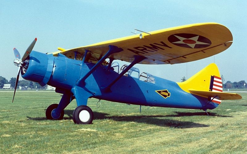
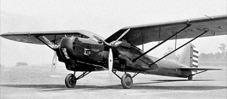
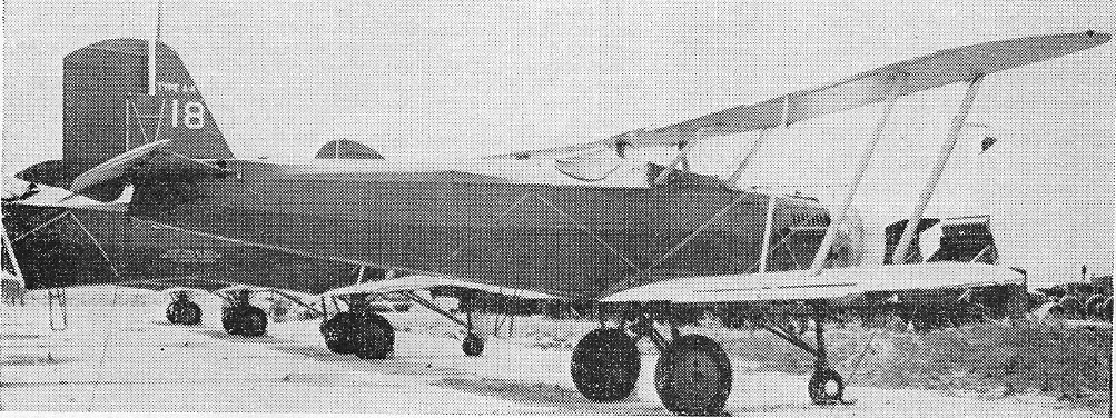
The Douglas O-46A was designed to operate from established airfields behind fairly static battle lines as in World War I. The O-46 was a development of the earlier Douglas O-43. The 24th airframe of the O-43A contract was completed as the XO-46 prototype, with a revised wing and an engine switch, from the O-43’s inline engine to a radial engine, the Pratt & Whitney R-1535-7.
First flying in 1935, the Air Corps ordered 90 O-46As in the same year. They were built between May 1936 and April 1937.
In 1939, a report was issued on the O-46A which stated that it was too slow and heavy to outrun and out-manoeuvre enemy fighter aircraft, too heavy to operate from small, wet, unprepared fields, and too large to conceal beneath trees. This report was a forecast of the future, for World War II with its rapidly changing battle lines proved the need for light, manoeuvrable observation aircraft which could operate from unimproved airstrips. Consequently, in 1942, the “O” (observation) designation was changed to “L” (liaison).
At least 11 O-46s saw overseas duty; two were destroyed in the Japanese raid on Clark Field in the Philippines on 8 December 1941. The Maryland Air National Guard operated O-46As off the coast of New Jersey for anti-submarine duty. The remainder were declared obsolete in late 1942 and after that were used primarily in training and utility roles.
A proposed variant with a Wright R-1670-3 engine received the designation O-48 but was not built.
On 27 November 1942, O-46A (s/n 35-179) was part of the 81st Air Base Squadron, when it landed downwind at Brooks Field, Harlingen, Texas, ran out of runway and overturned. Written off, it was abandoned in place. More than 20 years later it was discovered by the Antique Airplane Association with trees growing through its wings, and in 1967, it was rescued and hauled to Ottumwa, Iowa. Restoration turned out to be beyond the organization’s capability, and in September 1970, it was traded to the National Museum of the United States Air Force for a flyable Douglas C-47 Skytrain. The (then) Air Force Museum had it restored at Purdue University, and placed it on display in 1974, the sole survivor of the 91 O-46s built.
O-46A Powerplant: 1 × Pratt & Whitney R-1535-7 Twin Wasp Junior, 725 hp (541 kW) Propeller: 3-bladed metal propeller Wingspan: 45 ft 9 in (13.94 m) Wing area: 332 sq ft (30.8 m2) Length: 34 ft 6.75 in (10.5347 m) Height: 10 ft 8.5 in (3.264 m) Empty weight: 4,776 lb (2,166 kg) Gross weight: 6,639 lb (3,011 kg) Maximum speed: 200 mph (320 km/h, 170 kn) at 4,000 ft (1,200 m) Cruise speed: 171 mph (275 km/h, 149 kn) Range: 435 mi (700 km, 378 nmi) Service ceiling: 24,150 ft (7,360 m) Rate of climb: 1,765 ft/min (8.97 m/s) Wing loading: 20 lb/sq ft (98 kg/m2) Power/mass: 1.087 hp/lb (1.787 kW/kg) Guns: 2 × .30 cal (7.62 mm) Browning machine guns (one wing mounted and one flexible) Crew: 2
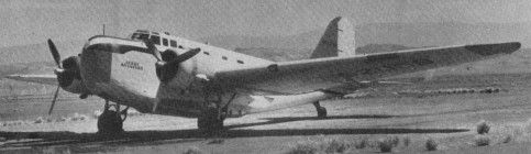
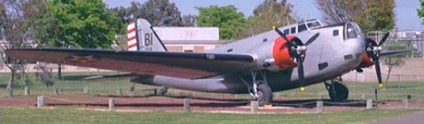
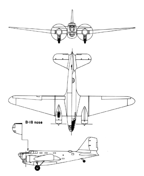
With a 1934 US Army Air Corps requirement for a bomber with greater capability than their Martin B-10, Douglas drew on engineering experience of the DC-2 commercial transport. Private-venture prototypes to meet the US Army’s requirements were evaluated at Wright Field, Ohio, in August 1935, these including the Boeing Model 299, Douglas DB-1 and Martin 146. The first was built as the B-17 Flying Fortress, the last was produced as an export variant of the Martin B-10/B-12 series, and the Douglas DB-1 (Douglas Bomber 1) was ordered in January 1936 into immediate production under the designation B-18. Derived from the commercial DC-2, the DB-1 prototype retained a basically similar wing, tail unit and powerplant. There were two differences in the wing: while retaining the same basic planform as the DC-2, the DB-1 had a 1.37m increase in span and was mounted in a mid-wing instead of low-wing position on an entirely new fuselage. The fuselage was deeper than that of the commercial transport to provide adequate accommodation for a crew of six, and to include nose and dorsal turrets, a bomb-aimer’s position, and an internal bomb bay. There was a third gunner’s position, with a ventral gun discharging via a tunnel in the underfuselage structure. Power was from two 694kW Wright R-1820-45 Cyclone 9 engines. 133 B-18s were covered by the first contract, including the single DB-1 which had served as a prototype. Production aircraft, which had the type name Bold, had equipment changes producing an increase in the normal loaded weight, and more-powerful Wright R-1820-45 radials. The last B-18 to come off the production line differed by having a power-operated nose turret, and carried the company identification DB-2, but this feature did not become standard on subsequent production aircraft. A second contract covered 217 B-18A aircraft, placed in June 1937 (177) and mid-1938 (40). This version differed by having the bomb-aimer’s position extended forward and over the nose-gunner’s station, and the installation of more-powerful Wright R-1820-53 engines. Most of the USAAC’s bomber squadrons were equipped with B-18s or B-18As in 1940, and the majority of the 33 B-18As which equipped the USAAC’s 5th and 11th Bomb Groups, based on Hawaiian airfields, were destroyed when the Japanese launched their attack on Pearl Harbor. When in 1942 B-18s were replaced in first-line service by B-17s, 122 B-18As were equipped with search radar and magnetic anomaly detection (MAD) equipment for deployment in the Caribbean on anti-submarine patrols under the designation B-18B. The Royal Canadian Air Force also acquired 20 B-18As which, under the designation Digby Mk I, were employed on maritime patrol. The designation B-18C applied to two other aircraft reconfigured for ASW patrol. Another two aircraft were converted for use in a transport role under the designation C-58, but many others were used similarly without conversion or redesignation.
B-18A Engines: 2 x Wright R-1820-53 Cyclone 9, 746kW / 986 hp Max take-off weight: 12552 kg / 27673 lb Empty weight: 7403 kg / 16321 lb Wingspan: 27.28 m / 89 ft 6 in Length: 17.63 m / 57 ft 10 in Height: 4.62 m / 15 ft 2 in Wing area: 89.65 sq.m / 964.98 sq ft Wing loading: 28.70 lb/sq.ft / 140.0 kg/sq.m Max. speed: 187 kts / 346 km/h / 215 mph Cruise speed: 145 kts / 269 km/h / 167 mph Service ceiling: 7285 m / 23900 ft Range: 1043 nm / 1937 km / 1204 miles Armament: 3 x 7.62mm (0.30in) machine-guns, 2948kg of bombs Crew: 6
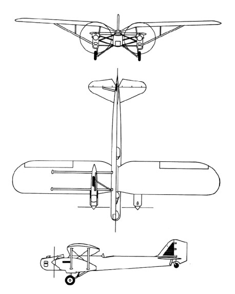
In the late 1920s the US War Department ordered two Fokker XO-27 prototypes. Fearing it might lose a valuable source of revenue, Douglas designed an aircraft incorporating all-metal cantilever monoplanes with retractable landing gear features and in March 1930 received an order for one example each of the Douglas XO-35 and Douglas XO-36. They were intended to differ only in their engines, the former having geared Curtiss Conquerors and the latter a direct-drive version of the same engine. In the event, the XO-36 was redesignated XB-7 and built as a bomber. In a parallel development the second of the Fokker XO-27s was completed as the XB-8 bomber. Later, six YO-27s and six Y1O-27s were delivered to the US Army.
The Douglas XO-35 was test-flown in spring 1931. It was a monoplane with a gull wing set high on the fuselage, the main units of its landing gear retracting into streamlined engine nacelles leaving only the lower part of the wheels exposed. The engine nacelles were attached to the wing undersurfaces and fuselage sides by complex strut assemblies, and the fuselage having corrugated metal sheet covering. There were open gunners’ cockpits in the nose and amidships; the pilot’s open cockpit was located immediately forward of the wing leading edge; and the fourth crew member, the radio-operator, had an enclosed cabin behind the pilot’s position. The XB-7 was almost identical, but had underfuselage racks for up to 544kg of bombs. During the US Fiscal Year 1932 orders were placed for seven Y1B-7 and five Y1O-35 service-test aircraft. These differed from the prototypes mainly by having smooth metal sheet covering for the fuselages, and strut- rather than wire-braced horizontal tailplanes. The Y1B-7s, later designated B-7, were attached to the two US Army bombardment squadrons based at March Field, California, while the O-35 aircraft (previously Y1O-35s) flew with observation units. In February 1934 the five O-35s, six surviving B-7s and XO-35 prototype were all assigned to the air mail route linking Wyoming with the west coast of the United States. Operations at night and in bad weather took their toll and in the four-month emergency period during which the US Army ran the nation’s air mail service no fewer than four of the B-7s were lost in crashes. Soon afterwards the remaining B-7s and O-35s were relegated to second-line duties, an O-35 being the last to be grounded in February 1939.
B-7 Crew: 4 Engine: 2 x Curtiss V-1570-53 Conqueror, 503kW Max take-off weight: 5070 kg / 11177 lb Loaded weight: 2503 kg / 5518 lb Wingspan: 19.81 m / 64 ft 12 in Length: 14.0 m / 45 ft 11 in Height: 3.53 m / 11 ft 7 in Wing area: 57.71 sq.m / 621.18 sq ft Max. Speed: 293 km/h / 182 mph Cruise speed: 254 km/h / 158 mph Ceiling: 6220 m / 20400 ft Range: 660 km / 410 miles Armament: 2 x 7.62mm machine-guns, 540kg of bombs
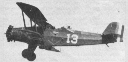
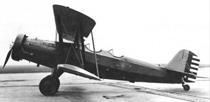
In 1926 as the principal combat element of Mexican Army Aviation, eight Douglas O 2C observation aircraft were procured from the USA these were to be supplemented by nine O 2Ms and three O¬2M 2s. The excellent flight characteristics of the Douglas O-2 family led to the conversion of 40 O-2Ks in 1930 as basic trainers for the US Army. Dual controls were installed and armament was deleted, the modified aircraft then being designated Douglas BT-1. The only O-32 to be built was given dual controls, also in 1930, and became designated BT-2. Thirty O-32As were modified similarly to the O-2Ks; used by US Army and National Guard units for basic training these were redesignated BT-2A. Some 146 BT-2B aircraft were built as such, the first appearing in 1931. Powered by the 336kW Pratt & Whitney R-1340-11 radial, they survived many years in basic training units.
BT
BT-2B was converted in 1940 to Type A-4 target aircraft by installation of radio equipment and conversion to nosewheel undercarriage.
Type A-4 target aircraft
Douglas BT-2B Engine: 1 x Pratt & Whitney R-1340-11 radial, 336kW Max take-off weight: 1845 kg / 4068 lb Empty weight: 1324 kg / 2919 lb Wingspan: 12.19 m / 39 ft 12 in Length: 9.5 m / 31 ft 2 in Height: 3.3 m / 10 ft 10 in Wing area: 33.63 sq.m / 361.99 sq ft Max. speed: 216 km/h / 134 mph Cruise speed: 188 km/h / 117 mph Ceiling: 5850 m / 19200 ft Range: 515 km / 320 miles
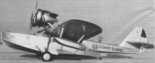
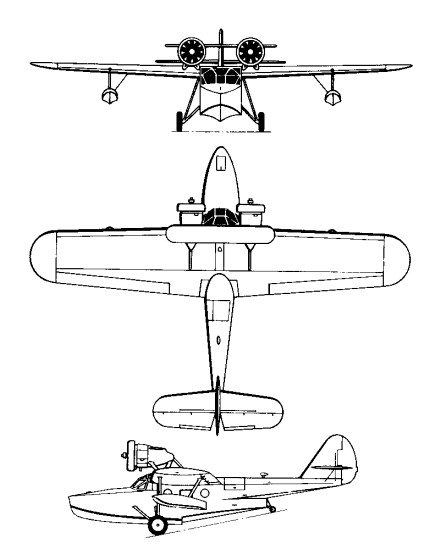
Completed in July 1930 as the non-amphibious Sinbad under civil registration NX145Y, Douglas’s first in-house flying boat design was initiall concieved as a “flying yacht” to be offered on the civilian market. The Sinbad appeared as a monoplane having an all-metal hull of semi-monocoque construction and a two-spar cantilever wing covered in plywood that featured slotted, Handley Page type ailerons. In original configuration, the 300-hp Wright J-5C Whirlwind engines were mounted directly above the wing and encased in nacelles that blended-in with its upper surface.
Several men examine Douglas Aircraft Co.’s new amphibian plane “Sinbad” at Clover Field (Santa Monica Airport). She became the prototype for the Dolphin series. Photo taken on July, 17, 1930, around the time of its first flight.
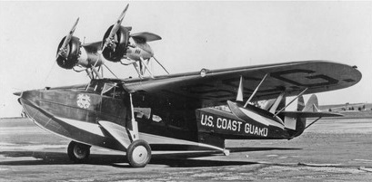
After flight testing revealed the need to raise the thrust line, the engines were moved above the wing on struts, along with an auxiliary airfoil mounted between the conical engine nacelles to add structural support and lift. When no civilian buyers surfaced, the Sinbad was sold to the Coast Guard in March 1931 for $31,500, where it operated for a period of time as call-sign “24 G” without a military designation but later simply listed as the “RD” with no numeric suffix.
Sinbad after Modifications
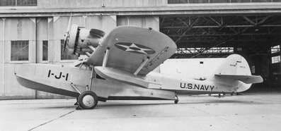
The improved Dolphin, equipped with amphibious landing gear, a modified hull, and 400 hp Pratt & Whitney R-1340 engines, emerged in early 1931 and two, known as the Dolphin I Speccial, were sold n June the same year to the Wilmington-Catalina Airline where they completed close to 40,000 crossings without incident. Military orders followed for 350 hp R-975 Whirlwind powered examples for the US Army Air Corp and another to the Navy as the XRD-1, both delivered in late 1931. Twenty-three more Dolphin variats were procured for the navy and the Coast Guard between 1932 and 1934; three RS-2s in early 1933, two to the Navy and one to the Coast Guard, powered by 450 hp Pratt & Whitney R-1340 engines; six very similar RD-3s in mid-1933 to the Navy; and ten RD-4s in late 1934 to the Coast Guard, powered by 450 hp R-1340-96 engines. One of the Navy RD-2s was specially outfitted for President Franklin D. Rooservelt but there is no record of it being used for such purpose. Navy RDs were assigned to utility squadrons and used primarily as transports, whereas Coast Guard versions saw extensive service in the search and rescue role as flying lifeboats. Two RD-3s were subsequently assigned to the Marine Corps to be used as utility transports. One aircraft reportedly manufactured as an RD-2 was used as a government transport by the Secretary of the Treasury until 1937. After the US entered World War II, RD-4s remaining in service with the Coast Guard were employed briefly for coastal patrol duties.
The authorities are in conflict as to the exact number of Dolphins accepted by the US Army Air Corp, however, it appears at least sixteen were delivered between 1932 and 1933. Two in 1932, powered by 300 hp Pratt & Whitney R-985 engines, eight in 1932 powered by 350 hp R-985-5 engines, as the C-26A; four in 1932-33, powered by 350 hp R-985-9 engines, as the C-26B, and two with enlarged cabins in 1933, powered by 575 hp R-1349-16 engines, as the C-29.
RD-2
In 1936-37 four OA-4As and one OA-4B were refitted with stainless steel wings, thn another OA-4B became the OA-4C when modified with experimental tricycle landing gear.
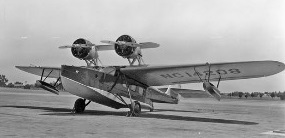
Civilian Dolphins, of which sixteen (including the two Dolphin I Specials) are estiated to have been built between 1933 and 1934, came in many variations ae decreaed by the preferences of individual customers. One registered as NC14286 was completed as a personal transport for William E. Boeing. French industrialist Armand Esders purchased a Dolphin powered by two 550 hp R-1340-51 engines, Standard Oil Company acquired two with 450 hp R-1340-56 engines to be used in overseas operations, and two more were built for the Vanderbilt family. In 1934 Pan American Airways bought two Dolphins that were operated by China National Airways Corp subsidary. After World War II began, one Dophin I Special and one from Standard Oil ended up flying in Australia with the RAAF.
RD-4 Engines: 2 x Pratt & Whitney R-1340-96 Wasp, 450 hp Props: 2 blade, ground adjustable, metal Wingspan: 60 ft 10 in / 18.29 m Wing area: 592 sq.ft / 55.0 sq.m Length: 45 ft 3 in / 13.74 m Height: 14 ft / 4.27 m Empty weight: 7000.9 lb / 3175.0 kg Gross weight: 9737 lb / 4323.0 kg Max speed: 147 mph / 136 kts / 251 km/h Cruise speed: 110 mph / 117 kts / 217 km/h Ceiling: 14,900 lb Range: 660 mi Seats: 8
C-21 Engine: 2 x Wright R-975-3, 261kW Max take-off weight: 3893 kg / 8583 lb Loaded weight: 2659 kg / 5862 lb Wingspan: 18.29 m / 60 ft 0 in Length: 13.36 m / 43 ft 10 in Height: 4.29 m / 14 ft 1 in Wing area: 52.21 sq.m / 561.98 sq ft Max. speed: 225 km/h / 140 mph Cruise speed: 192 km/h / 119 mph Ceiling: 4330 m / 14200 ft Range: 885 km / 550 miles
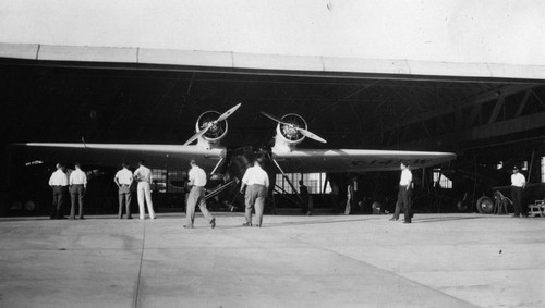
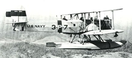
In July 1925 the US Navy Bureau of Aeronautics ordered three Douglas XT2D-1 twin-engined torpedo-bomber/ general-purpose biplanes. They were required to be suitable for use with wheel or float landing gear, and for operation from aircraft-carriers. Two months earlier a single XTN-1 aircraft, with similar general characteristics, had been ordered from the US Naval Aircraft Factory. The first XT2D-1 prototype flew on 27 January 1927 as a landplane. Soon afterwards its 373kW Wright P-2 radial engines were replaced by Wright R-1750s and the other two prototypes were similarly re-engined. The three aircraft participated successfully in trials with US Navy Torpedo Squadron VT-2 in spring 1927 and, nine examples of the production T2D-1 were purchased. The basic configuration of the XT2D-1 prototypes was retained, a large single fin and rudder, wide-track divided landing gear capable of easy conversion to take twin floats, and two-bay equal-span wings with rounded tips. The fuselage of the T2D-1 was 0.90m shorter than that of the XT2D-1 and the engine nacelles were repositioned. A crew of four was carried, the pilot and co-pilot in tandem open cockpits, with gunner/ bomb-aimer in the nose and radio-operator/gunner in the fourth cockpit amidships. The T2D-1 performed satisfactorily in service, operating from aircraft-carriers (being the first twin-engined aircraft to do so) during the 1928 US Navy fleet exercises. However, its size precluded embarkation of the carrier’s full aircraft complement and, as a result, the type was re-allocated to patrol squadrons. T2D-1s flew subsequently with VP-1 and VP-2 from Pearl Harbor, Hawaii, operating on wheels or twin floats as required until scrapped in 1933. Variant P2D-1: in June 1930 the Douglas company received an order for 18 aircraft based on the T2D-1, but intended specifically for over-sea patrol duties; these new P2D-1 aircraft had twin fins and rudders to ensure better flight characteristics, particularly with one engine inoperative, and were powered by 429kW Wright R-1820-E radial engines; deliveries were completed by the end of 1931 and the P2D-1s, almost always in twin-float configuration, flew with VP-3 of the US Navy stationed in the Panama Canal Zone, until withdrawn from first-line service in 1937.
T2D-1 Engine: 2 x Wright R-1750 radial piston engines, 391kW Take-off weight: 4773 kg / 10523 lb Empty weight: 2726 kg / 6010 lb Wingspan: 17.37 m / 56 ft 12 in Length: 12.80 m / 41 ft 12 in Height: 4.85 m / 15 ft 11 in Wing area: 82.31 sq.m / 885.98 sq ft Max. speed: 201 km/h / 125 mph Ceiling: 4215 m / 13850 ft Range: 735 km / 457 miles
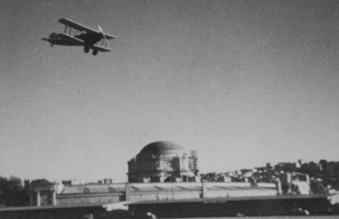
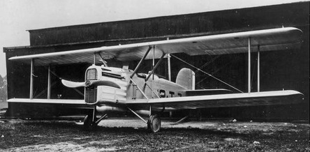
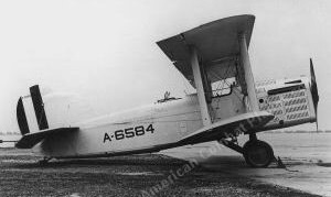
The DT was the first aircraft to be produced in quantity by Douglas aircraft. Based largely on the design of Douglas’s first plane, the Cloudster, the DT was a two-bay biplane featuring a welded, steel tube fuselage, with wings and tail surfaces of built-up wooden construction. It could be rigged as either a landplane or seaplane, and the wings could be folded rearward for stowage.
The 1921 DT-1 was a single-seat 298kW Liberty-powered (with side radiators) torpedo plane. In November 1921, the Navy took delivery of the first of three single seat DT-1s ordered, then after trials concluded in early 1922, directed that the remaining two be completed as two-seaters. Soon afterward, the Navy gave Douglas an order to produce 38 two-seat types as the DT-2 and also contracted L-W-F to build 20 and with NAF to build another six.
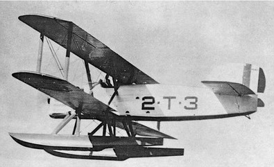
DT-2 2-T-3 of VT-2 early 1920s
The two-seat DT-2, a single-bay biplane was powered with a 335.3kW Liberty engine and nose radiator. The fuselage was of welded steel tubing, braced with tie-rods and provided with stiffening gussets. It was built in three detachable sections: engine section, mid-section and tail section, the first two plated with aluminium and the tail with fabric. The vertical tail surfaces had conventional wooden frames, while the horizontal tail surfaces were of steel tubing. The wings were of standard box-beam and built-up rib construction of wood, fabric-covered. The upper wing was made up of three panels, while the lower had the usual two. The undercarriage had a 3m wide track, although DT-2 could be fitted with two long wooden floats.
DT-2 of 2-T-3 VT-2 1923
As deliveries proceeded, DT-2s began entering operational service in late 1922 with VT-2 in San Diego, California, and during 1923 and 1924, at least six were transferred to the Marine Corps.
A total of about 80 production DT-2-type aircraft were produced in the USA, most as standard DT-2 for the US Navy but including a small number of SDW-1 scouting floatplanes, but excluding five export models delivered to Norway and Peru. The latter had 484.3kW Wright engines and were operated by the small Naval Air Station at Ancon (20 miles from Lima) which was under the command of US Navy officers on loan to the Peruvian government. Seven DT-2 were also built in Norway under licence.
US Navy DT-2 entered service from 1922 and during their four-year career were experimentally flown from the aircraft carrier USS Langley. Several new versions of the DT were developed by fitting new engines into existing DT-2, two NAF DT-2s became DT-4s when they were fitted with 525 hp Wright TA-2 engines, able to carry a bomb load of 748kg. Another modified as a testbed with the installation of a 40 hp Wright P-1 air-cooled radial engine was re-designated DT-6.
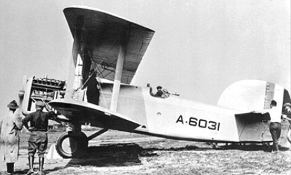
L-W-F DT-2
Three L-W-F DT-2s re-built by Dayton-Wright with deeper fuselages to carry more fuel returned to service as SDW long-range scouts. The 1924 Wright SDW-1 was an LWF DT-2 modified as a long-range USN scout with added fuel tanks. An open cockpit biplane, three conversions were made, including A6596. Landing gear was twin pontoons.
All DTs had been withdrawn from Navy and Marine service by the end of 1927.
DT-2 Engine: 1 x Liberty V-12, 336kW Take-off weight: 2950 kg / 6504 lb Empty weight: 1695 kg / 3737 lb Wingspan: 15.24 m / 50 ft 0 in Length: 10.41 m / 34 ft 2 in Height: 4.14 m / 13 ft 7 in Wing area: 65.68 sq.m / 706.97 sq ft Max. Speed: 163 km/h / 101 mph Ceiling: 2375 m / 7800 ft Range: 472 km / 293 miles Crew: 2 Armament: 1 x 830-kg torpedo
Douglas DT-2 Seaplane Engine: Liberty 12A, 420 hp Prop: 2 blade, fixed pitch, wooden Armament: 1 x .30 mg Bombload: 1 x 1835 lb torpedo Max sped: 99 mph at SL Ceiling: 7400 ft Combat range: 275 mi Empty weight: 4528 lb Loaded weight: 7293 lb Wingspan: 50 ft 0 in Length: 37 ft 8 in Wing area: 707 sq.ft Seats: 2 Total produced: 67
L-W-F DT-2 Engine: Liberty 12A, 420 hp Wingspan: 50 ft Length: 34 ft 2 in Height: 13 ft 7 in Wing area: 707 sq.ft Empty weight: 37 37 lb Gross weight: 6502 lb Fuel capacity: 115 Gal Top speed: 101 mph at SL Landing speed: 49 mph Service ceiling: 7800 ft Climb to 4050 ft: 10 min Range w/torpedo: 293 miles
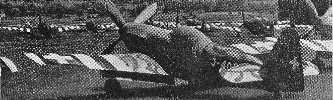
Swiss fighter aircraft. In 1938 the Swiss government purchased two Morane Saulnier M.S.405 fighters from France and, after careful evaluation, purchased a licence for the production version, the M.S.406C. Manufacture of a Swiss version of the 406 was assigned to Dornier Flugzeug at Altenrhein, with the Swiss designation D 3800. This differed from the French aircraft in having a Saurer/SLM licence built Hispano Suiza 12Y 31 of 860 hp, cooled by a fixed ventral radiator.
In 1939 40 Dornier delivered 82, followed in 1940 44 by 207 D 3801 fighters with many refinements and in having the 860 hp Hispano 12Y-31 engine replaced by a 1000 hp Hispano 12Y-51 built by A.G.Adolph Saurer.. Both types had one 20 mm (0.79 in) Hispano cannon and two 7.7 mm (0.303 in) wing guns, with provision for two 50 kg (110 lb) bombs.
D-3801
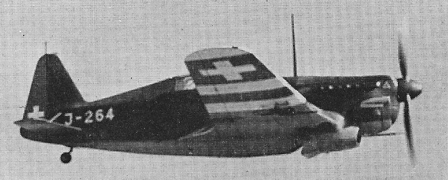
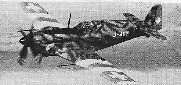
The D 3802 single-seat fighter prototype was built in 1943 by Dornier Werke to designs provided by Morane-Saulnier (designated M.S.450). A second prototype modified up to production standards was produced as the D-3802A, and orders were placed by the Swiss Air Force for 100. With the end of the war in Europe, the order was reduced to ten, built in 1944.
D-3802A
The 1500 hp (12Y 53) D 3803 of 1947 remained a one off, by which time the company had become Flug & Fahrtzeug¬werke (F&FW).
D 3801 Engine: 1000 hp Hispano 12Y-51 Span: 10.61 m (34 ft 9.75 in) Length: 8.16 m (26 ft 9.25 in) Empty weight: 4694 lb Gross weight: 2725 kg (6007 lb). Maximum speed: 523 km/h (325 mph) at 13,950 ft Econ cruise: 190 mph Time to 16,400 ft: 5.4 min Service ceiling: 35,400 ft
D-3802A Engine: Hispano-Suiza 1250 hp 12Y-52 Wingspan: 35 ft 2.75 in Length: 30 ft 7 in Height: 10 ft 11 in Empty weight: 6327 lb Loaded weight: 7716 lb Max loaded weight: 8014 lb Max speed: 391 mph at 21,325 ft Time to 19,865 ft: 7.1 min Ceiling: 33,500 ft Armament: three 20mm (0.79 in) cannon
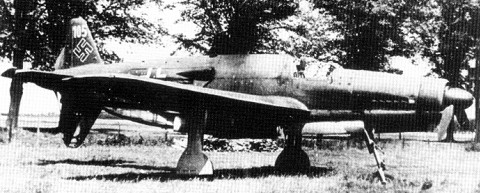
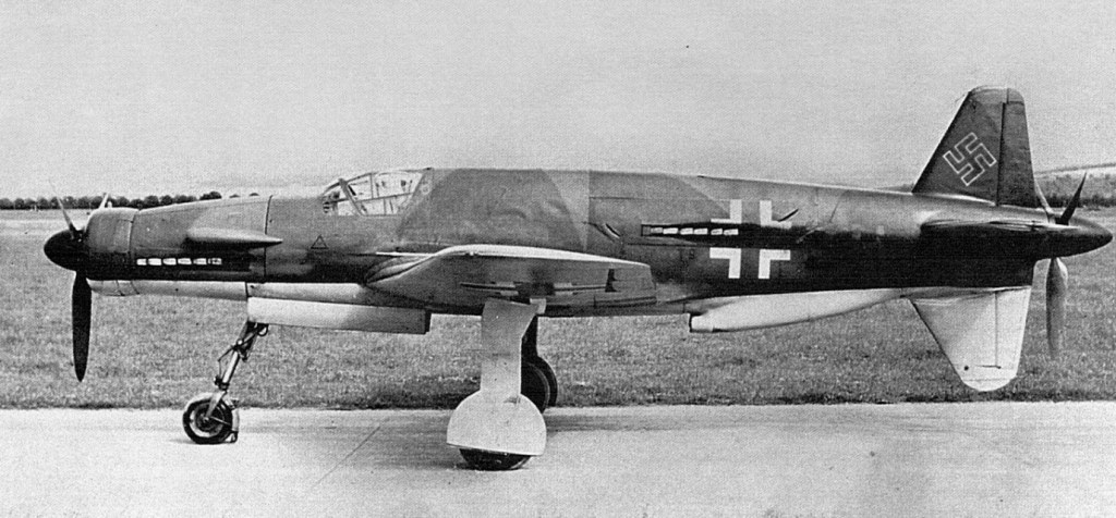
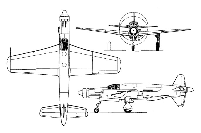
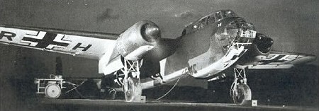
The unconventional layout of the Do-335 – one engine “pulling” in the nose and another “pushing” in the tail – was patented by Claudius Dornier in 1937. The configuration provided the power of two engines, but with reduced drag and better maneuverability. The German Aviation Ministry (RLM) was interested in the design, but initially wanted Dornier only to produce bombers. By 1942, Dornier was still continuing design work and the war situation was worsening. The Luftwaffe now needed a multi-purpose fighter, and the prototype Do-335V-1 (“V” indicating “versuchs” or “experimental”) flew in fighter form in September, 1943 – six years after its conception. Orders were immediately placed for 14 prototypes, 10 A-0 preproduction aircraft, 11 production A-1 single-seaters, and 3 A-10 and A-12 two-seat trainers. The aircraft was large for a single-seat fighter, with a cruciform tail and a tricycle landing gear. The two liquid-cooled Daimler-Benz DB-603 engines were used in four different versions, each displacing 44.5 liters (2670 cu in) and weighing 910 kg (2006 lb). The engine produced 1750 hp from 12 cylinders in an inverted V layout using fuel injection and an 8.3:1 compression ratio. The rear three-bladed propeller and dorsal fin were jettisoned by explosive bolts in an emergency, to allow the pilot to bail out safely using a pneumatic ejection seat. The seat, inclined 13 degrees to the rear, was ejected with a force of 20 times gravity. The ventral fin could be jettisoned for a belly landing. Unlike a normal twin-engined aircraft, with wing-mounted engines, loss of an engine on the Do-335 did not cause a handling problem. Even with one engine out, speed was a respectable 621 kph (348 mph). Because of its appearance, pilots dubbed it the “Ant eater” (“Ameisenbar”), although they described its performance as exceptional, particularly in acceleration and turning radius. The Do-335 was very docile in flight and had no dangerous spin characteristics. Many Do-335 prototypes were built, as the Reich strained desperately to provide day and night fighters and fast reconnaissance aircraft to the failing war effort. One of the many RLM production plans, issued in December 1943, called for the production of 310 Do-335s by late 1945. Initial production was at the Dornier Manuel plant, but this factory was bombed heavily in March-April, 1944, and the Do-335 tooling was destroyed. Powered by a pair of DB-603E liquid-cooled engines arranged in tandem, it has attained a speed in excess of 500 mph with both 12-foot, 3-blade propellers in operation. Operating on one engine, it can move along at a 350¬mph for several minutes.
Do 335 V3 T9+ZH delivered to 1./Versuchsverband OKL and test flown by Lt. Wolfgang Ziese
A big airplane by any standard, the 335 weighs more than 18,000 pounds with standard equipment and loading, topping 22,000 pounds in certain sub-types. With wing span and length of approximately 45 feet, it was originally built as a single seater only to emerge during the last year of war with a pig-a-back seating arrangement for training and reconnaissance utilization. The Dornier has a wing loading of 41 pounds per square foot in the standard model, wing load¬ing of 35 pounds per square foot in one high altitude type. However, interchangeability of armament and equipment brought wide divergence in gross loading on various mis¬sions. With a 520-gallon main tank installed behind the pilot’s compartment, two wing tanks, two drop tanks, and a bomb bay fuel cell, the aircraft carried a total of 1,000 US gallons of gasoline for a range of approximately 2,400 miles. With internal and external belly tanks removed, the Do-335 carried a single 1,000 kg, two 500 kg bombs, or ten 70 kg anti-personnel missiles in the bomb bay, along with one 250 kg bomb in each drop-tank shackle. The full fighter installation included one 30-mm gun firing through the propeller hub, one 20-mm gun on each side of the nose cowling within the propeller arc, and one 20- or 30-mm gun in each wing. Pilots were well-protected with a bullet-resistant glass windshield and cockpit enclosure, and an armored bulkhead between cockpit and main fuel tank. The trapezoidal wing, built around a heavy spar, has stressed metal skin, squared tips with detachable corners, leading edge de-icer, stowage for master unit of remote indicating compass, hydraulic tanks, oxygen bottles. On the A-6 version, radar antennae are mounted outboard on each wing. The all-metal monocoque fuselage is distinguished only by circular radiator in the nose, jettisonable mounting for rear propeller, cushioned stringers for hollow shaft to rear propeller, and explosive canopy release. In two-place models, the extra seat is above the leading edge of the wing and faces into the fuselage, with only the fuel tank separating this seat from the rear engine. The the Pfeil was never encountered in operations, although available in small numbers as the Do 335 A-1 single-seat fighter (with a maximum speed of 763km/h), Do 335A-6 two-seat night fighter and Do 335 B-series heavy fighter and night fighter towards the end of the war. It was the fastest production piston-engined fighter ever built, attaining 846 kilometers per hour (474 mph) in level flight at a time when the official world speed record was 755 kph (469 mph). Powered by two 1800-hp engines in a unique low-drag configuration.
Dornier Do-335A-1 Pfeil Wingspan: 13.8 m (45 ft. 3.33 in.) Length: 13.85 m (45 ft. 5.25 in.) Height: 5 m (16 ft. 4.75 in.) Weight empty: 7,400 kg (16,314 lb.) Max speed: 763 kph.
Dornier DO 335 A-02 Pfeil (Ameisenbär) Length : 45.604 ft / 13.9 m Height : 16.404 ft / 5.0 m Wingspan : 45.276 ft / 13.8 m Wing area : 414.414 sq.ft. / 38.5 sq.m Max take off weight : 20969.6 lb / 9510.0 kg Weight empty : 16317.0 lb / 7400.0 kg Max. speed : 395 kt / 732 km/h Service ceiling : 37730 ft / 11500 m Wing load : 50.64 lb/sq.ft / 247.0 kg/sq.m Range max fuel : 1161 nm / 2150 km Range w/max.payload: 1100 km / 684 miles Engine : 2 x Daimler Benz DB 603A, 1726 hp / 1800kW Crew : 1 Armament : 1x MK 103 30mm, 2x MG 151, 500kg Bomb. int. , 2x 250kg Bomb. ext.
Do-335A-6 two seat night fighter.
Do-335A-12 two seat trainer.
Do 335 Production List
Do 335V series prototypes, 14 aircraft built at Friedrichshafen, mid 1943 to mid 1944, and tested at Mengen.
Model: Do 335V-1 Code: CP+UA Werk Nr: 230001 Notes: 1st prototype. DB603A-1 engines. FF 28.10.43
Model: Do 335V-2 Code: CP+UB Werk Nr: 230002 Notes: to Rechlin, rear engine caught fire, w/o 15.04.44
Model: Do 335V-3 Code: CP+UC/T9+ZH Werk Nr: 230003 Notes: A-4 prototype, to Ob.d.L.
Model: Do 335V-4 Code: CP+UD Werk Nr: 230004 Notes: Do 435 prototype, not completed
Model: Do 335V-5 Code: CP+UE Werk Nr: 230005 Notes: 1st with armament fitted, A-2 engines
Model: Do 335V-6 Code: CP+UF Werk Nr: 230006 Notes: Dornier development a/c, hit by bomb
Model: Do 335V-7 Code: CP+UG Werk Nr: 230007 Notes: Junkers Jumo 213A & E testbed, Dessau
Model: Do 335V-8 Code: CP+UH Werk Nr: 230008 Notes: Daimler-Benz DB603E-1 testbed, Stuttgart
Model: Do 335V-9 Code: CP+UI/V9 Werk Nr: 230009 Notes: A-0 prototype, to Rechlin May 1944
Model: Do 335V-10 Code: CP+UK Werk Nr: 230010 Notes: A-6 prototype night ftr with SN-2 radar
Model: Do 335V-11 Code: CP+UL/11 Werk Nr: 230011 Notes: A-10 prototype trainer
Model: Do 335V-12 Code: CP+UM Werk Nr: 230012 Notes: A-12 prototype trainer
Model: Do 335V-13 Code: RP+UA/13 Werk Nr: 230013 Notes: B-1 prototype, to France for tests
Model: Do 335V-14 Code: RP+UB/14 Werk Nr: 230014 Notes: B-2 prototype, destroyed
Do 335A-0 pre-production batch, 10 aircraft built at Oberpfaffenhofen July-Oct 1944. One example converted to A-4 standard.
Model: Do 335A-0 Code: VG+PG/101 Werk Nr: 240101 Notes: DB603A-2 engines, at Rechlin July 1944
Model: Do 335A-0 Code: VG+PH/102 Werk Nr: 240102 Notes: sole survivor, to USAAF as FE 1012, now at NASM
Model: Do 335A-0 Code: VG+PI/103 Werk Nr: 240103 Notes: to Ob.d.L. late July 1944
Model: Do 335A-0 Code: VG+IJ/104 Werk Nr: 240104 Notes: to Erkdo 335 Sept 1944
Model: Do 335A-0 Code: VG+IK/105 Werk Nr: 240105 Notes: to Erkdo 335 captured by US at Lechfeld 4.45
Model: Do 335A-0 Code: VG+PL/106 Werk Nr: 240106 Notes: to Erkdo 335
Model: Do 335A-0 Code: VG+PM/107 Werk Nr: 240107 Notes: to Erkdo 335
Model: Do 335A-0 Code: VG+PN/108 Werk Nr: 240108 Notes: to Erkdo 335
Model: Do 335A-0 Code: VG+PO/109 Werk Nr: 240109 Notes: to Erkdo 335
Model: Do 335A-0 Code: VG+PP/110 Werk Nr: 240110 Notes: to Erkdo 335 Oct 1944
Do 335A-1 production batch. 11 aircraft built at Oberpfaffenhofen, plus 9 aircraft part assembled, Nov-April 1945.
Model: Do 335A-1 Code: 113 Werk Nr: 240113 Notes: Captured by US
Model: Do 335A-1 Code: Werk Nr: 240161 Notes: Captured by US
Model: Do 335A-1 Code: Werk Nr: 240162 Notes: Captured by US
Model: Do 335A-1 Code: 240163 Werk Nr: Notes: Captured by US
Model: Do 335A-1 Code: Werk Nr: 240164 Notes: Captured by US
Model: Do 335A-1 Code: Werk Nr: 240165 Notes: Captured by US
Model: Do 335A-1 Code: Werk Nr: 240166 Notes: Captured by US
Model: Do 335A-1 Code: Werk Nr: 240167 Notes: Captured by US
Model: Do 335A-1 Code: Werk Nr: 240168 Notes: Captured by US
Model: Do 335A-1 Code: Werk Nr: 240169 Notes: Captured by US
Model: Do 335A-1 Code: Werk Nr: 240170 Notes: Captured by US
Model: Do 335A-1 Code: 01 Werk Nr: 240301 Notes: Partly assembled Captured by US
Model: Do 335A-1 Code: 02 Werk Nr: 240302 Notes: Partly assembled Captured by US
Model: Do 335A-1 Code: 03 Werk Nr: 240303 Notes: Partly assembled Captured by US
Model: Do 335A-1 Code: 04 Werk Nr: 240304 Notes: Partly assembled Captured by US
Model: Do 335A-1 Code: 05 Werk Nr: 240305 Notes: Partly assembled Captured by US
Model: Do 335A-1 Code: 06 Werk Nr: 240306 Notes: Partly assembled Captured by US
Model: Do 335A-1 Code: 07 Werk Nr: 240307 Notes: Partly assembled Captured by US
Model: Do 335A-1 Code: 08 Werk Nr: 240308 Notes: Partly assembled Captured by US
Model: Do 335A-1 Code: 09 Werk Nr: 240309 Notes: Partly assembled Captured by US
Model: Do 335A-2 Code: Werk Nr: Notes: project only
Model: Do 335A-3 Code: Werk Nr: Notes: project only
Do 335A-4 10 aircraft scheduled Jan-Feb 1945, only 4 part assembled at Oberpfaffenhofen.
Model: Do 335A-4 Code: 10 Werk Nr: 240310 Notes: Partly assembled Captured by US
Model: Do 335A-4 Code: 11 Werk Nr: 240311 Notes: Partly assembled Captured by US
Model: Do 335A-4 Code: 12 Werk Nr: 240312 Notes: Partly assembled Captured by US
Model: Do 335A-4 Code: 13 Werk Nr: 240313 Notes: Partly assembled Captured by US
Do 335A-6 none assembled, Heinkel Vienna factory bombed out.
Do 335A-10 aircraft built at Oberpfaffenhofen.
Model: Do 335A-10 Code: 111 Werk Nr: 240111 Notes: flew late Nov 1944. Captured by US at Oberpf.
Model: Do 335A-10 Code: Werk Nr: 240114 Notes: not completed
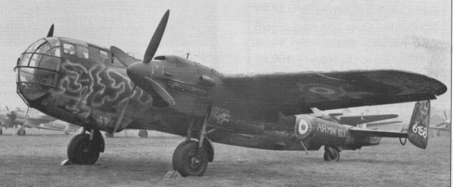
Do 335A-12. 2 aircraft built at Oberpfaffenhofen, plus 2 aircraft part assembled.
Model: Do 335A-12 Code: 112 Werk Nr: 240112 Notes: Air Min 225, to RAE, w/o 18 Jan 1946
Model: Do 335A-12 Code: 121 Werk Nr: 240121 Notes: to England, w/o 13 Dec 1945
Model: Do 335A-12 Code: 122 Werk Nr: 240122 Notes: not completed, scrapped by US
Model: Do 335A-12 Code: Werk Nr: Notes: Partly assembled
Do 335B series prototypes. 6 aircraft part assembled at Oberpfaffenhofen.
Model: Do 335B-2 Code: RP+UB 14/18 Werk Nr: 240118 Notes: B-2 replacement proto, to France with CEV until 4.6.48
Model: Do 335V-15 Code: RP+UC 15/19 Werk Nr: 240119 Notes: B-1 2nd prototype to Lwe 2.45
Model: Do 335V-16 Code: RP+UD 16/20 Werk Nr: 240120 Notes: B-2 2nd prototype night ftr with FuG 218
Model: Do 335V-17 Code: RP+UE 17/16 Werk Nr: 240116 Notes: B-6 prototype to France w/o Autumn 45
Model: Do 335V-18 Code: RP+UF 18/17 Werk Nr: 240117 Notes: B-6 2nd prototype night ftr to Lwe 2.45
Model: Do 335V-19 Code: RP+UG 19/15 Werk Nr: 240115 Notes: B-3 prototype not completed
Model: Do 335V-20 Code: Werk Nr: Notes: B-7 prototype not completed
Model: Do 335V-21 Code: Werk Nr: Notes: B-8 prototype not completed
Model: Do 335V-22 Code: Werk Nr: Notes: B-8 2nd prototype not completed
The Do 217 was one of the few completely new bombers to enter service with the Luftwaffe after the start of the Second World War. Though similar in configuration to the much earlier Do 17 series, it had a totally different structure and was much larger and more powerful. Like the contemporary Fw 190, the Do 217 was an all electric aircraft.
The first prototype, the Do 217 VI, first flew in August 1938. Developed from the basic Do 17 design but was stressed for heavier loads and had a dive brake fitted in the tail which opened out like an umbrella when the aircraft was used as a dive bomber but, With two 1150 hp DB 601 engines, was underpowered. Several prototypes followed, with the Jumo 211 of similar power, until the V7 of 1939 found more power with two of the 1550 hp BMW 139 radials. The Do 217 V7 abandoned the dive brake fitted in the V1 which had rarely been used since the bomber was better suited for level attacks than dive bombing. This engine was not put into production and the Do 217 changed to the heavier but more powerful BMW 801, rated at 1600 hp. Dornier had prolonged difficulties in achieving acceptable flying qualities and clearing the Do 217 for level and dive bombing, torpedo dropping, minelaying and later, reconnaissance, ground attack, anti-shipping strike and night fighting. The problem of poor handling was partially solved by the addition of fixed slots along the leading edges of the twin fins.
The first production version was the Do 217E, which was powered by two BMW 801A engines and armed with one fixed MG 151 and one flexible MG 151 machine-gun in the nose; one MG 131 in a manually operated dorsal turret; one MG 131 in a lower rear-firing position; and two MG 15s in lateral-firing positions.
In most versions a crew of four was accommodated, close together but in fair comfort, in the nose compartment. The wing had hot air de icing and accommodated flexible fuel cells between the spars, which passed through the top of the fuselage above the extremely large bomb bay. Early sub-types had a unique petal type dive bombing airbrake forming a long tailcone, but this was fairly soon abandoned.
The E-2 sub-version was similar but had an electrically operated turret, while the E-5 had attachments under the outer wings for two Hs 293 glider bombs for attacking convoys – special equipment for controlling these bombs was installed in the fuselage. Various armament schemes were fitted to prototypes and the E 0 and E 1, but the first major sub type, the E 2, had a fixed MG 151/15 forward firing cannon, an MG 131 in the dorsal turret, an MG 131 aimed manually from the lower rear and two to four 7.92 mm (0.312 in) MG 15 aimed from nose and beam windows. The Do 217E 2 was initially intended as a dive bomber and was fitted with an umbrella dive brake, and carried a 1000 kg (2200 lb) bombload.
Subsequent bomber versions had MG 81 machine guns in place of the MG 15, often in neat pairs; the R19 Rfistsatze pack (field modification kit) added four MG 81 firing aft in the tail. The bombload was typically 4000 kg (8818 lb), including about 1500 kg (3307 lb) hung externally. Most versions had a bomb bay long enough to accommodate two torpedoes internally. All early versions had 1580 hp BMW 801A or 801M engines with fan cooling and multiple fishtail exhausts.
A handful of E 0, E 1 and E 2 versions saw action over Britain in 1940 41, mainly with KG 40. The impressive capability of the 217 was marred by the structural and control hazards attendant upon steep dive bombing, and this technique was soon erased from the 217’s repertoire. The elimination of this role tended to accentuate the importance of the work already in hand in early 1941 for the development of air launched guided missiles for use against ships and similar important targets.
A Dornier Do 217E-4 was equipped with a Gerat 104 (104 device), prewar experimental design for an airborne anti-shipping gun. It was a recoilless gun firing a 635 kg (1400 lb) armour piercing shell. The gun was slung in the bomb bay and could be swung out when the Do 217 went into an attack.
The Dornier Do 217E 5 was the final production model of the E series and was designed to carry the Henschel Hs 293 rocket powered radio controlled glide bomb on pylons outboard of the engine nacelles. Do 217E 5s saw action with the Luftwaffe in the Mediterranean against the Royal Navy, US Navy and co belligerent Italian warships
The first missile to reach operational service was the Henschel Hs 293, weighing 1045 kg (2304 lb), which became operational with 11/KG 100 based at Cognac in August 1943.The Henschel missile was carried, two at a time, by the Do 217E 5, which was otherwise changed only by addition of the radio guidance equipment. Two days after the introduction of the missile, 11/KG 100 attacked and sank the corvette HMS Egret. Substantial numbers of E series bombers served on the Eastern Front from 1942, while the only Do 217 Geschwader(wing) to remain in the West, Kg 2, lost 65 of its original 88 crews between May and September of that year in sporadic missions against Britain.
On 9 September 1943 Italian Admiral Bergamini’s battleship and flag ship Roma (46,215 tons) was intercepted by 12 Do.217K-2 carrying Fritz X (SD 1400X) glide bombs. Shortly after 3:30pm the Roma was hit by two FX 1400 and torn in two. Admiral Bergamini and the 1254-man crew went down with the ship. Hitler and Goring were not informed of the FX 1400 because General Adolf Galland did not want Hitler any further pretext for increasing bomber production at the expense of fighter planes.
The Do 217K V1, the prototype of the K series which was flown with a single fin and rudder assembly. The K1 had an R25 tail housing to take the Perlon braking parachute which became a standard feature in later models. Though intended as a night bomber the K series could carry four L5 torpedoes or FX 1400 Fritz X stand off glider bombs. With the Do 217K 1 a more capacious crew compartment was introduced, being a redesigned deeper and more rounded nose. Most of this series had the 1700 hp BMW 8011), and the extra power enabled the wing of the K 2 version to be extended to 24.8 m (81 ft 41 in) to lift two of the formidable 1567 kg (3455lb) FX 1400 radio controlled free fall missiles on racks under the inner wings. The K was the fitting of a battery of four fixed rearward-firing MG 81 machine-guns in the tail-cone. Major Bernhard Jope’s III/KG 100 became operational with the FX missile on the Do 217K 2 in the late summer of 1943. They worked up at Graz, moved to Istres (Marseilles) and were ready when the Italian fleet sailed from La Spezia to join the Allies on September 9, 1943. Six K 2s sank the flagship, Roma, which went down with all 1255 men, and crippled Italia. Later Jope himself hit HMS Warspite and his unit sank or damaged other Allied ships during the Salerno landings.
The Do 217J was a somewhat hastily contrived night fighter, some being rebuilt ‘E’ series bombers with heavy nose armament and with light bombs in the rear bomb bay. The J 2 had Lichtenstein FuG 202 (sometimes and/or FuG 212) airborne radar, with a different arrangement of guns and the bomb bay filled with ammunition. The Do 217J 2 had a solid nose mounting four 20mm MG FF cannon, four 7.92mm MG 17 machine guns. The upper and lower rear guns of the E-2 were retained. Most of the ‘J’ series were passed to the Italian Regia Aeronautica (later Aviazione della RSI, after the September 1943 armistice) to help defend Milan and Turin by night.
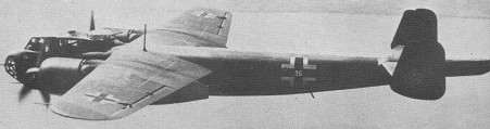
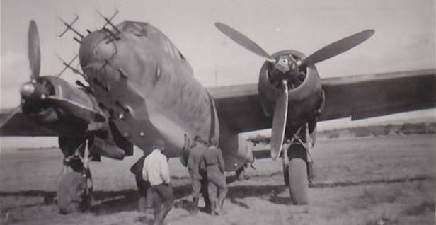
Do 217F with FuG Lichenstien BC antenna array, Sicily 1942/43
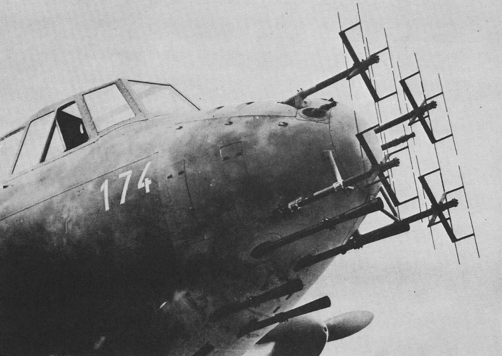
A modest production run of Do 217M bombers in 1943 had the 1750 hp DB 603A engine, while a nightfighter conversion of this model was the 217N. Some of the N series, such as the N 2/R22, had four MG 151 cannon firing steeply upwards at an angle usually near 70′ in the so called ‘Schrdge Musile’ scheme.
Dornier 217M-1
Do.217N-2 with FuG 202 radar, 4 x 20mm MG 151 cannon, 4 x MG 17 machine guns
The Do 217P was planned as a high altitude reconnaissance bomber with pressurized cabin for the crew of four and two DB 603B engines fed with boosted mixture by a vast supercharger in the fuselage driven by a DB 605T. The Do 217P O was a high altitude reconnaissance aircraft, though it could carry two 500 kg (1100 lb) bombs on underwing racks or two 900 litre (198 Imp gal) auxiliary tanks. It carried one Rb 20/30 camera and two Rb 75/30 as a reconnaissance aircraft, but a minimum of defensive armament principally because it flew out of range of enemy fighters. Although the P looked knobbly and bristled with engine inlets, radiators and intercoolers, it could fly at over 15 240 m (50 000 ft) and exceed 585 km/h (363 mph). The remaining 217P development aircraft were stripped of their pressurization and put into service as Do 217R missile carriers armed with the Hs 293. First flown in June 1942, this version failed to enter production. Total production of the Do 217 was only 1905. Of these, 1541 were offensive, the other 364 being night fighters.
Do 217 E Engines: 2 x BMW 801 Span: 19 m (62 ft 4 in)
Do 217 E-2 Engines: 2 x BMW 801 Span: 19 m (62 ft 4 in) Gross weight: 15000 kg (33069 lb) Maximum speed: 515 km/h (320 mph)
Do 217 J Engines: 2 x BMW 801 Span: 19 m (62 ft 4 in)
Do 217 K Engines: 2 x BMW 801 Span: 19 m (62 ft 4 in)
Do 217 K-2 Engines: 2 x BMW 801
Do 217 M Engines: 2 x Daimler-Benz DB 603 Span: 19 m (62 ft 4 in)
Do 217N Prop: four blade Wingspan: 62 ft 4 in Length: 58 ft 9 in Speed: 320 mph at 18,700 ft Ceiling: 31,170 ft Range: 1550 miles Armament: 4 x 20mm cannon, 4 x 7.9mm mg, 1 x 13mm mg Crew: 3
Do.217N-2 Engines: 2 x Daimler-Benz DB 603A, 1720 hp Wingspan: 62 ft 4 in Length: 62 ft Height: 16 ft 4.75 in Empty weight: 22,665 lb Combat weight: 29,101 lb Max speed: 320 mph at 19,685 lb Cruise: 264 lb Service ceiling: 29,200 ft Range: 1090 mi Armament: 8 x 20mm MG 151 cannon / 4 x 7.9mm MG 17 Radar: FuG 202/212 or SN-2