Vickers FB.27 Vimy / Vimy Commercial

Design of the Vickers F.B.27 was initiated in 1917 to meet the requirement to provide bomber aircraft able to attack strategic targets in Germany from bases in Britain. The Vimy was one of three new-generation bombers with which the RAF planned to take the air war to Germany in 1919. Such aircraft as the de Havilland D.H.10 Amiens and Handley Page V/1500 were also built.

Vickers Vimy Article

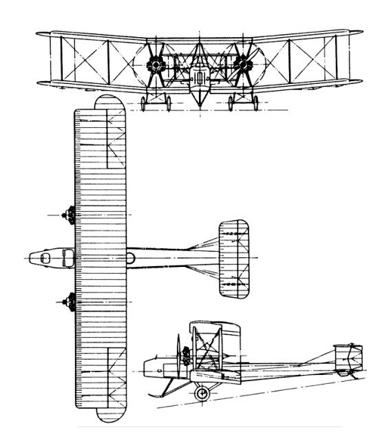
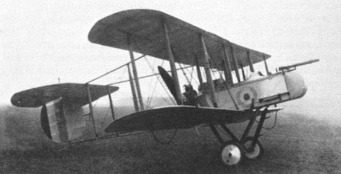
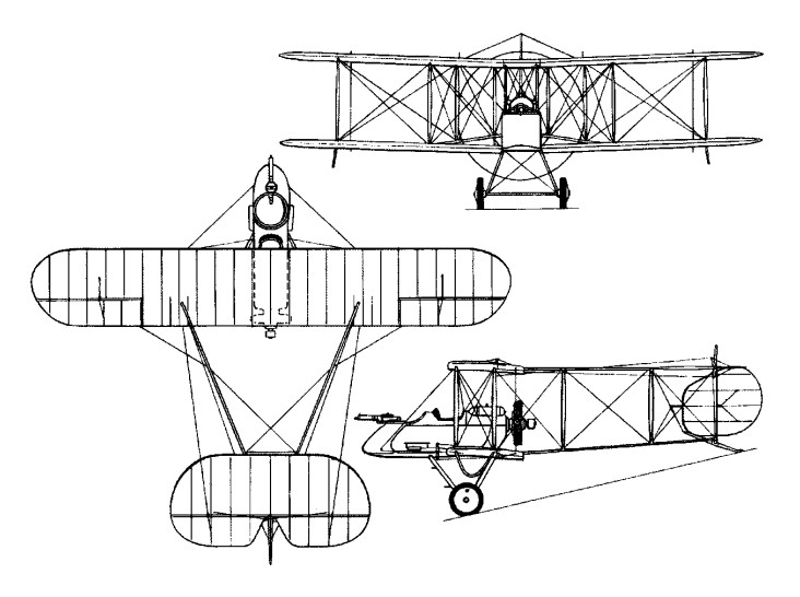
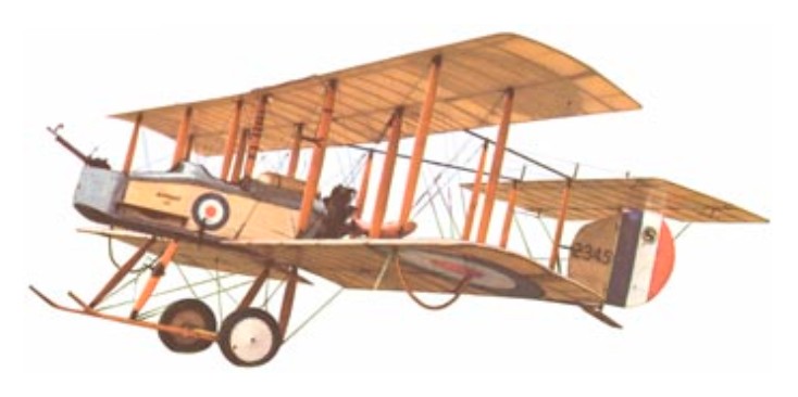
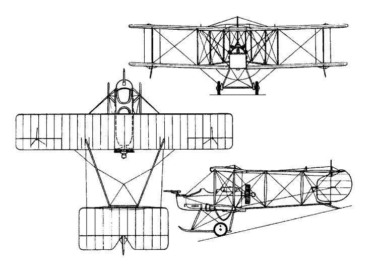
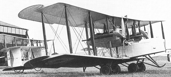
The F.B.27 was a three-bay biplane of conventional construction, with a biplane tail unit which had twin fins and rudders. The wing centre-section – almost one-third span – had the fuselage at its centre with large struts supporting the upper wing. At the outer ends of this centre-section the engines were mounted midway between the upper and lower wings. Two twin-wheel main landing-gear units were mounted beneath the lower wing, one directly below each engine. Outboard of this centre-section the wings had dihedral.

The largest aircraft then built by Vickers, it posed many construction problems; but despite this the first prototype, B9952, flew on 30 November 1917 – little more than four months after the design had been started. This aircraft was powered by two 149kW Hispano-Suiza engines (subsequently re-engined with 194kW Salmsons). Three further prototypes followed, powered respectively with 194kW Sunbeam Maoris, 223kW Fiat A-12s and 268kW Rolls-Royce Eagle VIIIs. It was the latter installation which was selected for production aircraft.

With the introduction of official aircraft names in 1918, the F.B.27 became the Vimy. But only a single example had been placed on an operational footing before the Armistice, which meant that none were used operationally in World War I.

The main production version was the Vimy Mk IV with Eagle VIII engines. Large contracts were cancelled at the end of the war but total Vimy Mk IV production amounted to 240, the last batch of 30 being ordered in 1925. The type entered service in July 1919 with No.58 Squadron in Egypt, home to another three squadrons; the type was retired from Middle Eastern service in August 1926 after operating the Cairo-Baghdad air mail service.

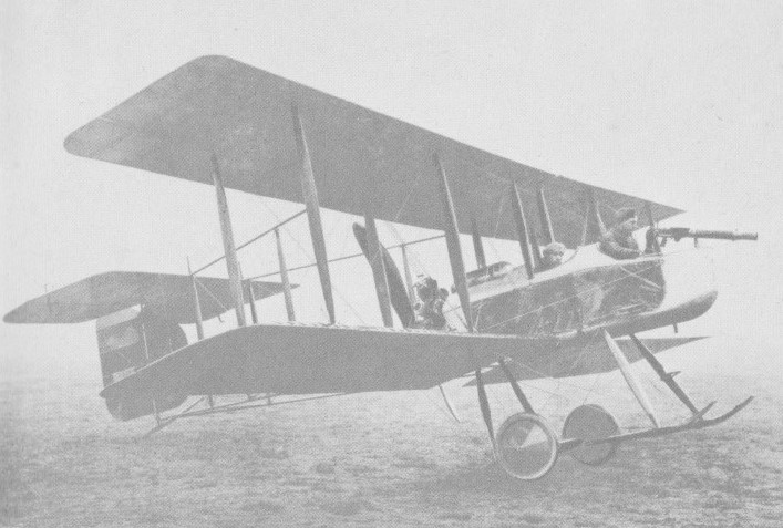
About 300 Vimy IVs of the standard production version were built, each with two 360 hp Rolls-¬Royce Eagle VIII engines. They carried a crew of three and 2476 lb of bombs, and were armed with twin Lewis machine guns in nose and midships positions.

Five home-based squadrons operated the Vimy, which was replaced as a first-line bomber by the Virginia during 1924 and 1925 but remained operational with No. 502 Squadron until January 1929.

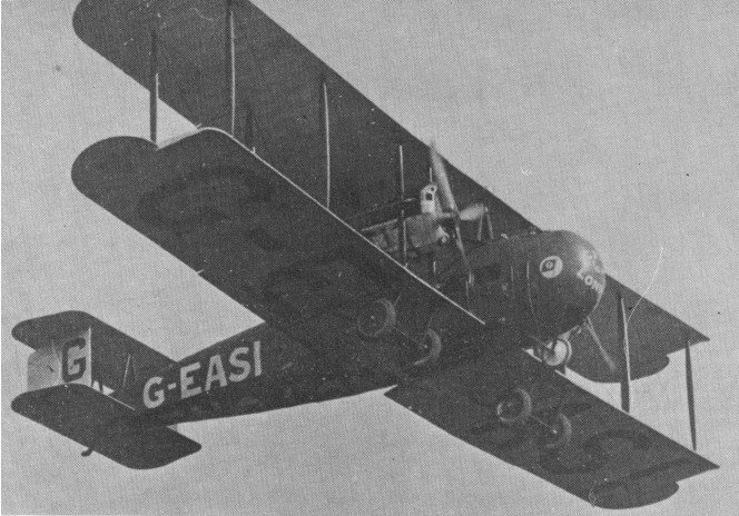
Conversions carried 10 passengers. A small number of commercial and ambulance aircraft were built, known simply as Commercial Vimys. The Commercial was fundamentally the same as the Vimy bomber, with the same wings, engine and tail, but had a rounded fuselage, capable of taking up to ten passengers the two flying crew braving the elements in a high set open cockpit in the nose. G EAAV was the prototype Vimy Commercial, having first flown (as K107) on April 13, 1919.

Vickers Vimy Commercial Article

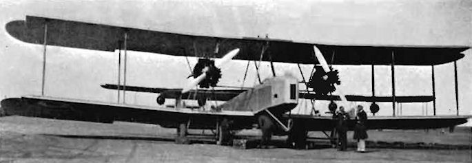
A number of Vimys were used for flying and parachute training duties. Revived as an advanced instructional aircraft for training pilots in multi-engined flying. For this purpose Jupiter VI or Jaguar engines were fitted in about 80 aircraft.

No. 4 FTS Armstrong-Siddeley Jaguar powered Vimy at Abu Sueir, Egypt, in 1930

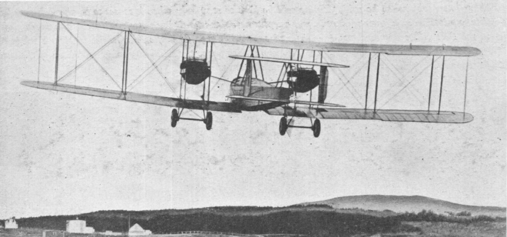
The Vimy is remembered especially in aviation history for the post-war long-distance flights which pointed the way to the air lanes that would link the world. First was the flight by Capt John Alcock and Lt Arthur Whitten-Brown across the North Atlantic, from St John’s, Newfoundland, to Clifden, Eire, during 14-15 June 1919 in a time of 16 hours 27 minutes.

Take-off from St.Johns, Newfoundland
Landing in a bog at Clifden, Ireland, and almost over-turned.

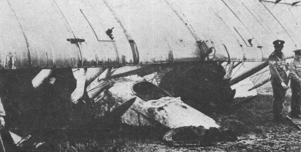
Next was the England-Australia flight of the brothers Capt Ross and Lt Keith Smith, together with Sgts Bennett and Shiers. Taking off from Hounslow (not far from today’s Heathrow Airport) on 12 November 1919, they landed safely at Darwin on 10 December 1919 in an elapsed flying time of 135 hours 55 minutes. Last of the trio of great Vimy flights was an attempt by Lt-Col Pierre van Ryneveld and Sqn Ldr Christopher J. Q. Brand of the South African Air Force to link London and Cape Town. On 4 February 1920 they took off from Brooklands, unfortunately making a crash landing between Cairo and Khartoum. Loaned a second Vimy by an RAF unit in Egypt, they continued to Bulawayo, Southern Rhodesia, where they failed to get airborne because of ‘hot and high’ conditions. They finally completed their flight to Cape Town in a third borrowed aircraft (a de Havilland D.H.9), arriving at their destination on 20 March 1920. They, like Alcock and Brown and the Ross brothers, were awarded knighthoods for their achievement.

Vickers Vimy Atlantic Crossing

In 1919, the Chinese government ordered perhaps 100 (or maybe 40) Vickers Vimy transports to be used to establish passenger service in China. Most remained in their shipping crates; only seven were put into use.

Gallery

Replicas
Vintage Aircraft & Flying Association Vimy

Engines: 2 x 360hp Rolls Royce VIII
Length 43.5 ft (13.2 m)
Wing span 67.1 ft (20.5 m)
Height: 15 ft. 7.5 in
Wing area 1318 sq. ft
Weight loaded: 10885 lb
Weight empty 7,100 lb (3,220 kg)
Crew: 4
Armament: Two machine guns, one each in nose and aft cockpits
Bomb load: 18 x 112 lb (50 kg) bombs 2 x 230 lb (104 kg) bombs
Max speed: 89 kts / 103 mph (166 kph)
Ceiling: 7,000 ft (2,100 m)
Range: 1,000 miles (1,600 km)
Range max. weight: 391 nm / 725 km
Initial climb rate: 295.28 ft/min / 1.5 m/s

Vimy Mk II
Engines: 2 x Rolls-Royce Eagle VIII, 268kW
Max take-off weight: 4937 kg / 10884 lb
Empty weight: 3222 kg / 7103 lb
Wingspan: 20.75 m / 68 ft 1 in
Length: 13.27 m / 44 ft 6 in
Height: 4.76 m / 16 ft 7 in
Wing area: 122.44 sq.m / 1317.93 sq ft
Max. speed: 166 km/h / 103 mph
Ceiling: 2135 m / 7000 ft
Range w/max.fuel: 1448 km / 900 miles
Armament: 2 x 7.7mm machine-guns, 1123kg of bombs
Crew: 3

Vimy Mk IV
Type: three-seat heavy night bomber
Span: 20.75m (68 ft 1 in)
Length: 13.27m (43ft 6.5 in)
Powerplant: 2 x Rolls-Royce Eagle VIII, 268kW (360 hp)
Armament: 2 x 7.7-mm (0.303-in) machine-guns
Bombload: 1123 kg (2,476 lb)
MTOW: 5647 kg (12,500 lb)
Max speed: 103 mph at 6,500 ft
Operational range: about 900 miles

Vickers F.B.27 Vimy

Vickers FB.19

Designed in 1916 by G H Challenger and flown for the first time in August of that year, the F.B.19 was a single-bay unstaggered equi-span biplane with a single 7.7mm Vickers gun mounted on the port side of the fuselage and a 100hp Gnome Monosoupape engine. Ordered by the War Office for the RFC, the series version was powered by either the Gnome or the 110hp Le Rhone. Some 50 F.B.19s were built, and, late in 1916, a batch of six was sent to France where, after operational evaluation, the fighter was deemed un-suited for the fighting conditions then evolving. At this time, some of the F.B.19s were delivered to the Russian government following demonstrations in Petrograd, Moscow, Kiev and Tiflis, but several were still in their crates on the docks at Archangel at the commencement of the Bolshevik revolution. These aircraft were destroyed by the Royal Navy, but a few others assembled prior to the Navy’s action were flown in Bolshevik service. A modified version, the F.B.19 Mk II, was developed with wing stagger and either the Le Rhone or Clerget 110hp rotary. Only 12 Mk IIs were built and several of these were included in a batch of 12 F.B.19s sent to the Middle Eastern theatres of war. These were flown in Palestine and Macedonia from June 1917, but no squadron used the type exclusively and it was not well liked.

F.B.19
Engine: 1 x Gnome Monosoupape, 75kW
Max take-off weight: 670 kg / 1477 lb
Empty weight: 405 kg / 893 lb
Wingspan: 7.31 m / 24 ft 0 in
Length: 5.54 m / 18 ft 2 in
Height: 2.51 m / 8 ft 3 in
Wing area: 19.97 sq.m / 214.96 sq ft
Max. speed: 158 km/h / 98 mph
Ceiling: 5180 m / 17000 ft

Vickers F.B.19

Vickers FB.12

A compact two-bay biplane of pusher type, the F.B.12 was designed for the 150hp Hart static radial engine, in the development of which the Hart Engine Company was being assisted by Vickers.

With a single-seat nacelle faired out to a circular cross section and mounted in mid wing-gap, and tailbooms converging in side elevation to meet at the rear spar of the tailplane, the F.B.12 had a basic structure primarily of steel tube.

Vickers FB.12 Article

Unavailability of an airworthy Hart engine led to the first F.B.12 being fitted with an 80hp Le Rhone rotary, with which it flew in June 1916. Although underpowered, it demonstrated a creditable performance when tested at the Central Flying School in the following August. The Le Rhone was then replaced by a 100hp Gnome Monosoupape, and, subsequently, new wings of greater span were fitted – overall span being extended by 1.09m – with straight raked rather than elliptical tips. Redesignated F.B.12A, this aircraft was sent to France for operational evaluation in December 1916.

A further aircraft was built – by Wells Aviation of Chelsea – with the Hart engine as the F.B.12B. This was flown early in 1917, but promptly crashed, helping to seal the fate of the Hart radial. A contract for 50 aircraft powered by the Hart had, on 10 November 1916, been awarded Vickers, the intention being to fit the series aircraft with a new, wooden nacelle and enlarged vertical tail surfaces as the F.B.12C.

Production of the F.B.12C was sub-contracted to Wells Aviation, but with the loss of the F.B.12B, the Hart engine was abandoned. In the event, only 18 F.B.12C airframes were completed and these were fitted with a variety of engines, including the 110hp Le Rhone nine-cylinder rotary and the 100hp Anzani 10-cylinder radial.

Testing at Martlesham Heath in May 1917 revealed insufficient elevator control at low speeds, heavy lateral control and other problems. Furthermore, the gun (a 7.7mm Lewis) was considered to be badly positioned for changing ammunition drums. By this time, tractor fighters of superior performance were in RFC service and further development of the F.B.12 was therefore discontinued.

F.B.12C
Max take-off weight: 656 kg / 1446 lb
Empty weight: 420 kg / 926 lb
Wingspan: 9.02 m / 29 ft 7 in
Length: 6.65 m / 21 ft 10 in
Height: 2.62 m / 8 ft 7 in
Wing area: 22.02 sq.m / 237.02 sq ft
Max. speed: 140 km/h / 87 mph
Ceiling: 4420 m / 14500 ft

Vickers F.B.12

Vickers FB.9

Dubbed unofficially the Streamline Gunbus, the F.B.9, which emerged towards the end of 1915, introduced numerous refinements over its predecessor, the F.B.5. The fuselage nacelle was of improved aerodynamic form; the wings and tailplane sported rounded tips; streamlined Rafwires replaced stranded steel cables and turnbuckles for interplane bracing, and a plain, Vee-type undercarriage supplanted the twin skids previously used.

The standard power plant remained the 100hp Gnome Monosoupape rotary. Vickers (Wells Aviation) built a total of 95 F.B.9s (5271 to 5290 and A1411 to A1460) plus the prototype (7665), and a further 24(7812 to 7835) were built by Darracq in France, some of which were issued to the RFC (No 11 Sqn) and were used during the Battle of the Somme which began on 1 July 1916. The manufacture of the F.B.9 in Italy by Vickers-Terni fell through owing to political reasons.
The only FB.9s known to have seen operational service were seven examples (Serials 7812, 7813, 7820, 7826, 7827 and 7828), all of which were flown on war patrols by 11 Squadron RFC in France in June July 1916. On July 1, 7828 gained a confirmed aerial combat victory. All other FB.9s were relegated to RFC and RNAS training units, where they gave faithful service until late 1918. As trainers, several FB.9s were modified to have dual controls, and many had a Scarff ring fitted in the front cockpit for gunnery practice. At least one FB.9 was armoured and fitted with an oleo undercarriage. None remained on charge at the time of the Armistice.

Engine: 100 hp Gnome Monosoupape rotary, or 110 hp Le Rhone rotary
Span: 10.3 m (33 ft 9 in)
Length: 8.7 m (28 ft 5.5 in)
Height: 3.5 m (11 ft 6 in)
Wing area: 31.59 sq.m / 340.03 sq ft
Max take-off weight: 858 kg / 1892 lb
Empty weight: 467 kg / 1030 lb
Maximum speed: 132.9 km/h (82.6 mph) at ground level
Climb to 3048 m (10000 ft): 51 min
Service ceiling: 3353 m (11000 ft)

FB.9
Engine: Gnome Monosoupape, 100 hp
Wingspan: 33 ft 10 in
Wing area:
Length: 27 ft 10 in
Height: 7 ft 0 in
Empty weight: 1029 lb
Loaded weight: 1892 lb
Wing loading:
Max speed: 79 mph at 6500 ft
Service ceiling: 11,000 ft
Endurance: 5 hr
Rate of climb: 19 min to 6500 ft
Armament: 1 x Lewis gun
Crew: 2

Vickers F.B.9

Vickers EFB-5 / FB.5 Gunbus / Vintage Aircraft & Flying Assoc. FB.5 Gunbus

Progressive changes introduced by successive E.F.B.3s led to the E.F.B.5 – the E.F.B.4 being a project with a more streamlined nacelle centred between the wings and only two tailbooms – which was flown from Joyce Green to Brooklands on 17 July 1914. In parallel, Vickers developed the E.F.B.6, which, basically similar to the E.F.B.5, had longer-span upper wings. It lacked top decking between the two crew seats and had ailerons in the upper wings only. At Brooklands on 14 July 1914, the E.F.B.6 was taken on strength by the Royal Flying Corps when World War I began, but was not developed.

No orders were received but Vickers felt certain that war was imminent and began building 50 F,B.5s. These were eventually taken over by the RFC, which put a total of 241 in service. The E.F.B.5 was ordered into production for both the RFC and the RNAS on 14 August 1914, the first series aircraft being completed in the following October. At this time, the aircraft became simply F.B. (Fighting Biplane) 5 and was dubbed Gunbus. The E.F.B.5 had retained the semi-circular tail-plane of the E.F.B.2 and early E.F.B.3, but the series F.B.5 had an enlarged tailplane of rectangular planform and a larger rudder. A Lewis gun on a more practical mount supplanted the similar-calibre Vickers in the nose and the standard power plant was the 100hp Gnome Monosoupape nine-cylinder rotary.

The true fighter squadron was born on the 14 February 1915 when No.11 Squadron was formed at Netheravon. Completely equipped with Vickers FB5 aircraft this was the first unit established purely with the intention of destroying other aircraft.

The first F.B.5 reached the Western Front early February 1915, and, on the following 25 July, the first squadron of any air service formed specifically for fighting duties and equipped throughout with a single aircraft type arrived in France, this being the RFC’s No 11 Sqn with F.B.5s.

The RNAS made little use of the F.B.5, and, after the delivery of four to that service, the large majority of subsequent deliveries went to the RFC, although the RNAS did receive two further F.B.5s which, ordered in May 1915, were fitted with the 150hp Smith Static radial engine, its large diameter propeller necessitating the raising of the fuselage nacelle several inches above the lower wing. Two hundred and forty-one F.B.5s were delivered to the RFC, of which 109 were sent to the British Expeditionary Force in France (60 in 1915 and 49 in 1916). Licence production of the F.B.5 was undertaken in France by the Societe Anonym Darracq (which built a total of 99 of these and the later F.B.9) between May 1915 and June 1916. Twelve were also built under licence in Denmark in 1917-18 by the Tojhusvasrksted. At least four F.B.5As were built with armour-plated fuselage nacelles and these were powered by 110hp Clerget 9Z nine-cylinder rotary engines and had oleo undercarriages. Suffering an unreliable engine and a marginal performance throughout its operational career, the F.B.5 was finally withdrawn from the Western Front in the autumn of 1916, being subsequently confined to RFC instructional units.

Built by members of the Vintage Aircraft Flying Association for eventual display at the RAF Museum, a Gunbus reproduction was powered by a Gnome 100 hp Mono rotary with original prop.

Vintage Aircraft Flying Association Gunbus reproduction

The Vintage Aircraft & Flying Assoc. FB.5 Gunbus was built in 1966 at Weybridge. Registered G-ATVP c/n VAFA.01, it first flew at Wisley on 14 June 1966. It was stored for a short while at Henlow but then went on display in the RAF Museum at Hendon.

Vintage Aircraft & Flying Assoc. FB.5 Gunbus at RAF Museum

Gallery

Engine One 100 hp Gnome Monosoupape
Length 27 ft 2 in (8.25m)
Wing span 36 ft 6 in (11.1m)
Height: 3.38 m / 11 ft 1 in
Wing area: 35.49 sq.m / 382.01 sq ft
Weight empty 1,220 lb (553 kg)
Max take-off weight: 930 kg / 2050 lb
Max speed: 70 mph (113 kph) at 5000 ft
Range: 402 km / 250 miles
Service ceiling: 9,000 ft (2,700 m) fully loaded
Endurance 4.5 hours
Seats: 2
Armament: One Lewis machine gun, plus small bombs

FB.5
Engine: Gnome Monosoupape, 100 hp
Wingspan: 36 ft 6 in
Wing area: 362 sq.ft
Length: 27 ft 2 in
Height: 11 ft 0 in
Empty weight: 1220 lb
Loaded weight: 2050 lb
Wing loading: 5.4 lb/sq.ft
Max speed: 60 mph at 5000 ft
Service ceiling: 9000 ft
Endurance: 4 hr
Rate of climb: 19 min to 6500 ft
Armament: 1 x Vickers mg
Crew: 2

Vickers F.B.5 Gunbus

Valtion Humu

The Humu – literally “Reckless” – was produced by Valtion Lentokonetehdas. It was not that the Humu was unconventional in any respect. It was a copy of a seven-year-old American design adapted to make use of locally-available materials and captured equipment, and built without benefit of licence or assistance from the parent manufacturer. The Finnish air arm, Ilmavoimat, had acquired 43 Brewster B-239 shipboard fighters that had been declared surplus to US Navy requirements. These had proved singularly successful in Ilmavoimien service, and, in 1942, it was proposed that an attempt be made by the VL to remedy a shortfall of fighters of this type by producing a copy. Because of shortages of metal, this was to make as much use as possible of wood and to embody so-called “war booty” instrumentation and power plant – equipment captured from the Soviet forces by the Finns themselves and similar equipment captured by the Wehrmacht and sold to the Finns. The task of designing an entirely new wooden wing was assigned to M T Vainio, who was also responsible for the overall project, and, in October 1942, an order was placed with the VL for four prototypes, the intention at that time being to build a series of 90 aircraft. The chosen engine was the 930hp Shvetsov M-63, which was flown on 5 June 1943 in a B-239. Static testing of the wooden wing was not entirely satisfactory. Nevertheless, in September 1943, orders were confirmed for five prototypes of the Humu and 55 production aircraft. The wooden wing was found to add 250kg to air-frame weight, however, and the transfer of the fuel tanks from the wing to the fuselage shifted the CG aft, adversely affecting manoeuvrability. Initiation of series production was, therefore, delayed pending results of prototype tests, and in the summer of 1944 the programme was terminated as it was concluded that the Humu would have inadequate combat capability by the time it achieved service. Only one prototype Humu was completed, and this, having an armament of three 12.7mm guns and a mix of Finnish and Soviet instrumentation, flew on 8 August 1944. The M-63 engine failed to give its full power during subsequent flight testing, but 19 hrs 50 min were flown before, in 1945, the sole example of this aircraft was placed in storage.

The performance of VL Humu was not measured. The information of maximum speed is based on tests of wooden wing and M-63 motor in Brester 239 (BW-392) October 1942. BW-392 was 350 kg heavier than VL Humu and those days the Finns did not adjust the M-63 correctly due to lack of the instruction manual. The Finns got the instruction manual from Germany in 1943.

The prototype of VL Humu (HM-671) is in The Aviation Museum of Central Finland in Tikkakoski, Finland.

Max take-off weight: 2895 kg / 6382 lb
Empty weight: 2050 kg / 4520 lb
Length: 8.03 m / 26 ft 4 in
Max. speed: 430 km/h / 267 mph

Valtion Myrsky

On 8 June 1939, the VL (Valtion Lentokonetehdas) received a contract from the Ministry of Defence to design a new single-seat fighter. Chief designer was Dipl Ing A Ylinen, who was assisted by T Verkkola and M Vainio, and, within nine months of receiving the definitive prototype contract on 20 December 1940, the prototype of the Myrsky (Storm) was in final assembly. A conventional low-wing cantilever monoplane, the Myrsky had a plywood-skinned two-spar wooden wing and a welded steel-tube fuselage covered by dural panels forward and fabric aft. Power was provided by a Pratt & Whitney R-1830-SC3-G Twin Wasp 14-cylinder radial rated at 1115hp for take-off. The prototype was flown on 23 December 1941, but immediately encountered the first of what were to be many teething troubles.
On 30 May 1942, the VL received a contract for three development aircraft which were to embody numerous detail structural and other changes, these including an increase in wing area of 1.3sq.m and a change in armament from two 12.7mm and four 7.7mm guns to three (in first and second) or four (in third aircraft) of the larger-calibre weapons. The first of these was completed on 30 April 1943, but crashed a week later, and the second suffered a wheels-up landing three months later, and broke up in the air shortly after resuming flight test. The third was evaluated in service, and, on 17 March 1944, lost both wings in a dive.
In the meantime, VL had initiated production of the first series model which was referred to as the Myrsky II Series. All the progressive changes that had been introduced in the pre-series aircraft were incorporated, armament was standardised on four 12.7mm LKK/42 guns, and by the end of July 1944 the VL had completed 14 of the II Series aircraft, a further 16 having been delivered by the truce of 4 September. Production continued after the truce and the last five of the 47 built were delivered straight to the Air Force Depot on 30 December 1944 without flight testing. The Myrsky II series was assigned to a tactical reconnaissance squadron (TLeLv 12) which received its first aircraft on 23 July 1944, 20 being delivered to the squadron before the Armistice, and a second squadron (TLeLv 16) initiating conversion to the Myrsky meanwhile. The Myrsky was flown operationally over Lapland against the Wehrmacht under the terms of the Finnish-Soviet agreement, but Ilmavoimat flew this fighter only to a limited extent, and the service’s doubts as to its durability and sturdiness, despite continuous reinforcement of various components, finally came to a head on 9 May 1947 when a Myrsky broke up in a dive, all aircraft of this type then being grounded.

Max take-off weight: 3213 kg / 7083 lb
Empty weight: 2337 kg / 5152 lb
Wingspan: 11.00 m / 36 ft 1 in
Length: 8.35 m / 27 ft 5 in
Height: 3.00 m / 10 ft 10 in
Wing area: 18.00 sq.m / 193.75 sq ft
Max. speed: 535 km/h / 332 mph
Range: 500 km / 311 miles

UTVA C-3 Trojka / BC-3 / Ikarus 251 / Cijan C-3 Trojka

The Utva C-3 Trojka (Trey) was a light aircraft built in Yugoslavia shortly after World War II as a result of a government competition to develop a new, domestically built aircraft with which to equip the country’s flying clubs. The winning design was submitted by Boris Cijan and Dragoslav Petkovic and the prototype was built by Ikarus as the Ikarus 251.

The prototype first flew towards the end of 1946. Series production took place at Utva as the C-3 and the first production Trojka were delivered in 1949. It was a conventional, low-wing cantilever monoplane with fixed tailwheel undercarriage. The pilot and instructor sat side by side under an expansive canopy.

The type remained in production until the mid-1950s. Later examples were powered by a 105 hp Walter Minor 4-III engine from 1953. About eighty were built.

The type was operated by the Yugoslav Air Force.

Gallery

Engine: 1 × Walter Mikron III, 49 kW (65 hp)
Wingspan: 10.49 m (34 ft 5 in)
Wing area: 15.5 m2 (16.7 ft2)
Length: 8.84 m (29 ft 0 in)
Height: 2.08 m (6 ft 10 in)
Empty weight: 374 kg (824 lb)
Gross weight: 602 kg (1,328 lb)
Maximum speed: 166 km/h (103 mph)
Cruise speed: 90 mph
Range: 605 km (376 miles)
Service ceiling: 3,900 m (12,800 ft)
Crew: Two, pilot and instructor

UFAG C.I / 161 / Neuschloss-Lichtig NL Sportplane

The UFAG C.I was a military reconnaissance aircraft produced in the Austro-Hungarian Empire during World War I, by the Ungarische Flugzeugfabrik Abteil Gesellschaft (UFAG). It was introduced in April 1918, and was widely used on the Italian Front in the final months of World War I.

The UFAG C.I incorporated the best features of the Brandenburg C.II(U) with single-bay wings and ‘I’ strut inter-plane bracing, which was replaced wing conventional steel-tube interplane struts in production aircraft. More manoeuvrable than the Phönix C.I, the C.I had good performance, but suffered from a few odd handling characteristics.

Ufag C.Is in service

Production of the C.I continued after the Armistice by MARE and was also built by the Neuschloss-Lichtig factory as the NL Sportplane.

UFAG Brandenburg C.I aircraft in Albertfalva (Budapest) in 1916

The C.I was widely used by the KuKLFT on the Italian front by at least 30 Fliks. The C.I was also used post WWI by the Hungarian Red Airborne Corps as well as the clandestine Hungarian Legügyi Hivatal. Ex-military C.Is were also converted for civil use and as mailplanes.

Twenty UFAG C.I were captured from the Hungarian Soviet Republic in 1919 and used by the Romanian Air Corps.

Variants:

Ufag 161.01
First prototype 8.92 m (29.3 ft) span, 200 hp (150 kW) Hiero 6, ‘I’ type inter-plane struts.

Ufag 161.02
Second prototype, 230 hp (170 kW) Hiero 6, ‘I’ type inter-plane struts.

Ufag C.I
(series 161.03 to 161.22) Production by Ufag, 9.12 m (29.9 ft) span, 230 hp (170 kW) Hiero 6, twin inter-plane struts.

Ufag C.I
(series 161.31 to 161.250) Production by Ufag, 9.5 m (31 ft) span, 230 hp (170 kW) Hiero 6, twin inter-plane struts.

Ufag C.I(Ph)
(series 123.01 to 123.40) Production by Phönix, 9.12 m (29.9 ft) span, 230 hp (170 kW) Hiero 6, twin inter-plane struts.

UFAG 60.01
an improved C.I which would evolve into the UFAG 60.03 / C.II.

Specifications:

C.I second series 161.23 – 161.250
Powerplant: 1 × Hiero 6, 170 kW (230 hp)
Propeller: 2-bladed wooden fixed-pitch
Upper wingspan: 9.5 m (31 ft 2 in)
Lower wingspan: 9.4 m (30 ft 10 in)
Wing area: 26.3 m2 (283 sq ft)
Length: 7.41 m (24 ft 4 in)
Height: 2.7 m (8 ft 10 in)
Empty weight: 750 kg (1,653 lb)
Gross weight: 1,150 kg (2,535 lb)
Maximum speed: 190 km/h (120 mph, 100 kn)
Range: 350 km (220 mi, 190 nmi)
Endurance: 3 hours
Service ceiling: 4,900 m (16,100 ft)
Guns: 1 x 8 mm (0.315 in) Schwarzlose machine-gun forward-firing fixed machine guns; 1 x 8 mm (0.315 in) Schwarzlose machine-gun in trainable rear cockpit mounting
Bombs: 12 x 12 kg (26 lb) bombs (161.131 onwards)
Crew: 2

Turkish Aerospace Industries Kaan

The Kaan program, initiated in 2016 with an investment of $1.18 billion, was designed to replace Türkiye’s aging F-16 fleet. Developed with international collaboration from partners such as BAE Systems and Rolls-Royce, the program prioritizes local production and technology ownership. The aircraft incorporates advanced design features, including supercruise capability and reduced radar cross-section, alongside a suite of indigenous munitions such as the Gökdoğan and Bozdoğan air-to-air missiles. The program emphasizes network-enabled warfare capabilities and interoperability with UAVs and other air force assets.

The Kaan, developed by Turkish Aerospace Industries (TAI), is a fifth-generation twin-engine stealth fighter designed for air superiority and multirole operations. It is equipped with advanced AESA radar capable of detecting targets over 100 kilometers away, internal weapon bays to reduce radar visibility, and a payload capacity of more than 6,000 kilograms. Initial models are powered by General Electric F110 engines, with plans to integrate domestically developed engines in later versions. The Kaan is designed to operate with other platforms in the Turkish Air Force, including the F-35A.

The TAI TF Kaan, a fifth-generation stealth fighter jet, achieved its maiden flight on February 21, 2024, with a second successful flight on May 6, 2024.

Engines: General Electric F110
Wingspan: 14 m
Length: 21 m
Height: 6 m
Speed: Mach 1.8
Operating altitude: 55,000 ft
Combat range: of approx 1,100 km