Fairey Flycatcher

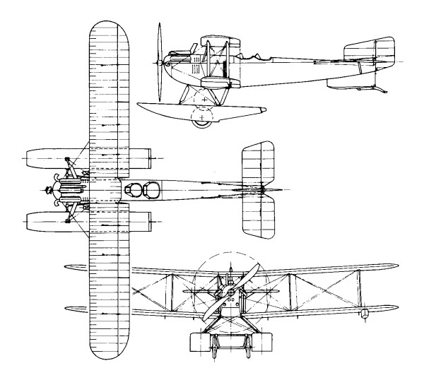
The Specification 21/26, issued by the Air Ministry’s Directorate of Technical Development (DTD) on September 30, 1926, called for a “Single Seater Fighter Ship¬-plane for use from HM ships,” fitted with a land undercarriage which could be replaced by floats, and vice versa, within half an hour. The aircraft, which was to have an all metal structure but could be fabric covered, was to be suitable for launch from a catapult and for taking off from and alighting on the deck of an aircraft carrier. It was to have a good degree of positive stability about all axes in both configurations, and tail incidence had to be adjustable in flight to enable the aircraft to fly horizontally at all speeds without attention from the pilot.
It was to be “highly controllable” at all speeds, and especially close to stalling speed, with no tendency to ‘hunt’ in a steep dive. Control had to be adequate to stop an incipient spin when the machine was stalled. A high degree of manoeuvrability in the air and on the ground or water was desired, and it had to respond quickly to the controls while not being tiring to fly. The ailerons were to have the minimum of yawing effect.
As a seaplane, the machine was to have good static stability in the water, and when under tow or running under its own power it was to be stable about all axes at all speeds.
The engines specified were the air cooled Bristol Mercury radial of 550hp at 2,000rpm or the water cooled Rolls Royce Falcon X of 480hp at 2,300rpm. The installation had to allow for rapid and easy removal of the engine. The cowling, which also had to be easily removable, had to be finished “to prevent the reflection of light which might betray the presence of the aircraft to the enemy or dazzle the pilot”. A metal propeller was specified.
There was to be tankage for 74 gallons of fuel, plus an easily removed 20 gallon auxiliary tank and a gravity tank of sufficient capacity to allow half an hour’s flight at full power at ground level. An 11 gallon oil tank was to be provided if the Mercury engine was used, or an 81/2 gallon oil tank and a 21/2 gallon reserve water tank for the Falcon.
Alternative exhaust systems for day or night flying were required, and were to be easily changed. The night flying system had to provide adequate silencing and flame damping, while the daytime system was to be “of minimum weight”. Additional equipment to be carried during the acceptance flights weighed 5581b and included a Vickers 0.5in gun and 300 rounds, a Vickers 0.303in gun and 600 rounds, a rocket launching (R/L) tube and six bombs, and flotation gear. A second 0.303in gun with 600 rounds was to be provided for if the 0.5in gun was not available in time.
Minimum performance requirements with this load, using the Mercury, called for a horizontal speed of 132kt (152mph) at 10,000ft and a service ceiling of 23,000ft. With the Falcon X the figures were 127kt (146mph) at 10,000ft and 22,000ft. The length of run to take¬off was not to exceed 47ft in a relative wind of 28kt (32mph), and the aircraft was to become airborne at a speed of 55mph when catapulted in still air. The suitability for launching from a catapult or alighting on the deck of an aircraft carrier was “of first importance”, and the aircraft had to be capable of taking off from a turret or cruiser platform.
For fighting, the pilot was to have the best possible view in all directions, and a good view forward and downwards was required for carrier landings. A clear, unobstructed view forward over the machine’s centreline was needed to enable him to sight the fixed guns, the installation of which was to dispense with blast tubes. There was also to be provision for the fitting of a G.3 aerial camera as near to the sights as practicable, and standard clips were to be fitted to allow the new “light carrier” to be installed to carry four 20 lb bombs, sufficient clearance being provided to enable the bombs to be released in a very steep dive.
Despite the emphasis placed on the machine’s naval use, it was stressed that: “The aircraft is to be designed primarily as a landplane fighter and qualities required for this work are not to be sacrificed in order to improve its characteristics when equipped with the float alighting gear”. A padded head support was to be provided to prevent injury to the pilot during catapult launch acceleration.
A limit of 35ft was put on the wing span, the overall length was restricted to 23ft, the height was not to exceed 14ft 9in. Quick and easy removal and erection of the wings was specified, with the ability to remove the wing structure completely in ten minutes and replace it in fifteen minutes.
The contractor was required to provide a full size mock up of his proposed aircraft before constructional work was begun, to enable the Director of Technical Development to examine and approve the layout. This mock up had to include “all parts and components which are likely to interfere with the all round view of the pilot”, and was to show the internal arrangement of the cockpit. Scale model floats for official water tank tests were also to be provided, along with specimens of ribs, a section of wing, and a length of spar.
Tendering for this demanding specification were Armstrong Whitworth, which offered the AW XVI; Fairey, with the Flycatcher II; Gloster, which tendered the Gnatsnapper; Hawker, which offered the Hoopoe; Vickers, with a modified version of its Type 141 Scout; and George Pamall & Co, which had its head office at the Coliseum Works, Park Row, Bristol, and its aerodrome at Yate, in Gloucestershire.
The prototype flew for the first lime in 1922, and 192 were delivered to the Fleet Air Arm as Britain’s standard carrier-based fighters until replaced by the Nimrod.

Flycatcher and HMS Eagle

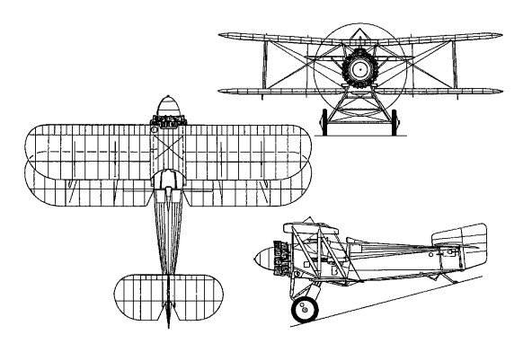
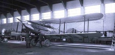
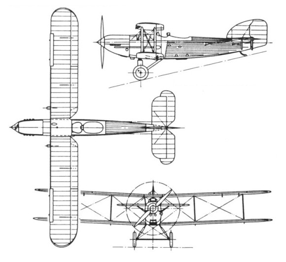
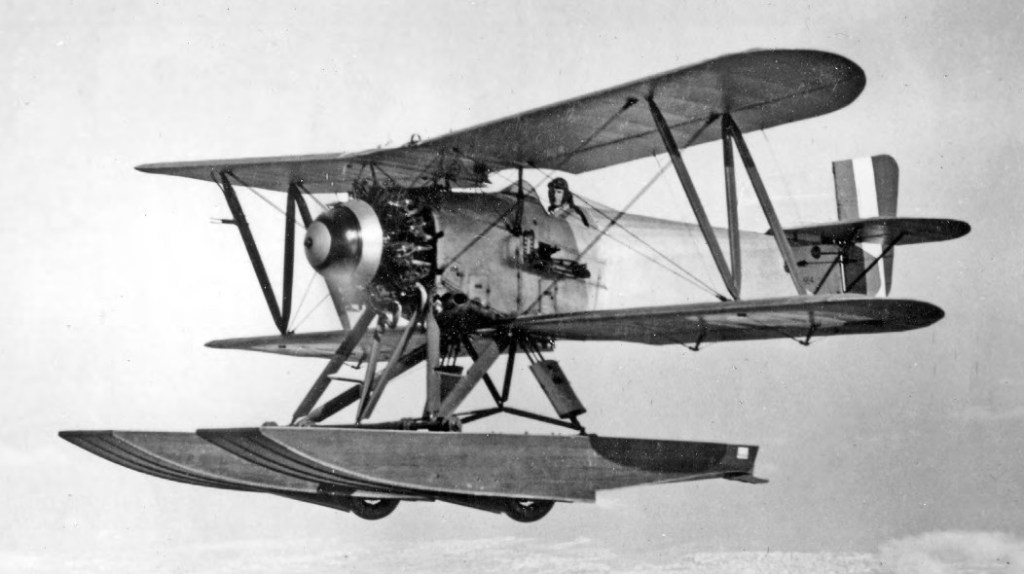
Construction was composite with wooden fabric-covered wings and a fuselage of wood and metal with fabric covering. A single-bay biplane wings, well-staggered, with pronounced dihedral on the upper wing (plus Fairey’s Patent Camber Gear) and a fuselage which appeared to curve upwards to the tail unit.
The Flycatcher was the first aircraft required by the Air Ministry to undertake a terminal velocity dive at the maximum speed to which its 400 hp Jaguar IV engine would thrust it.

Hendon 1924

The aircraft of 403 Flight took part in operations against Chinese Pirates in the mid twenties.
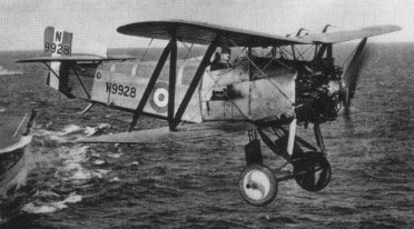
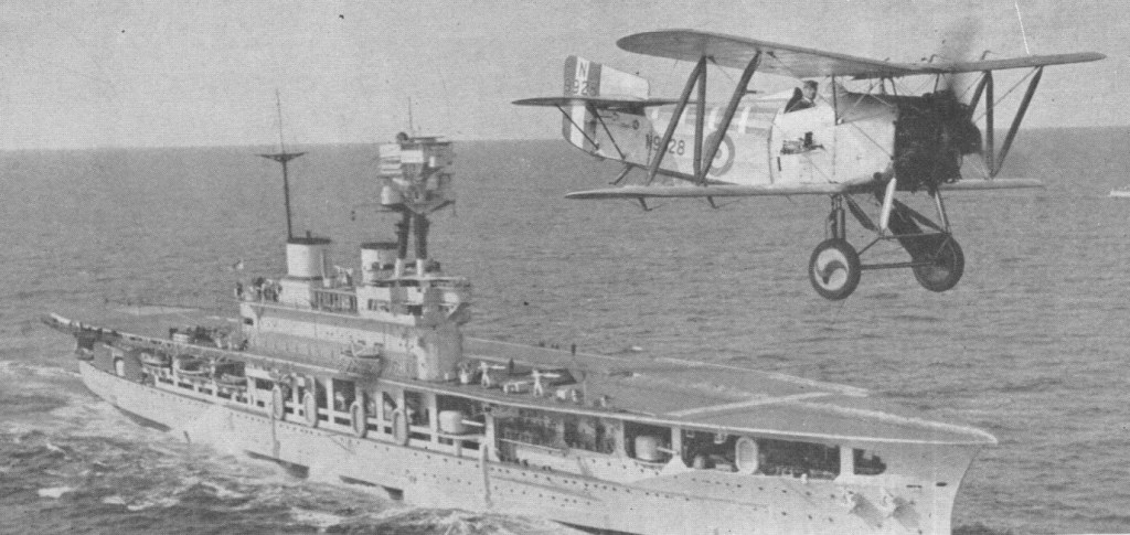
Flycatchers remained in service from 1923 until declared obsolete in 1935. They had the distinction of serving on board all British aircraft carriers of that period. In addition, they operated as landplane fighters from a short 18.3m take-off platform mounted above the gun turrets of capital ships. Their trailing-edge flaps and drooped ailerons provided a steep path of descent which was ideal for carrier landing. One Flycatcher was fitted experimentally with hydraulic brakes which permitted a very short landing run. This was the first FAA aircraft to have such brakes, but they did not then become standard equipment.
Once on deck, they did not have the benefit of folding wings to simplify shipboard stowage. Instead they were designed to be dismantled easily into sections which did not exceed 4.11m in length. The training, skill and enthusiasm of deck handling crews made possible such feats as a record of six aircraft landed and stowed in their hangars in only 4 minutes 20 seconds. Landing was carried out on the main deck.

Replica:
Westward Airways Fairey Flycatcher

Flycatcher
Engine: 1 x Armstrong Siddeley Jaguar III or IV, 400hp
Wingspan: 8.84 m / 29 ft 0 in
Length: 7.01 m / 23 ft 0 in
Height: 3.66 m / 12 ft 0 in
Loaded weight: 3028 lb
Max. speed: 133 mph at 5000 ft
Range at max speed: 263 miles at 10,000ft
Armament: 2 x 7.7mm machine-guns, 4 x 9kg bombs

Flycatcher I
Wingspan: 8.84 m / 29 ft 0 in
Length: 7.01 m / 23 ft 0 in
Height: 3.66 m / 12 ft 0 in
Wing area: 26.76 sq.m / 288.04 sq ft
Engine: 1 x Armstrong Siddeley Jaguar III, 298kW
Max take-off weight: 1372 kg / 3025 lb
Empty weight: 924 kg / 2037 lb
Max. speed: 216 km/h / 134 mph
Ceiling: 5790 m / 19000 ft
Range at 110 mph: 500 km / 311 miles
Armament: 2 x 7.7mm machine-guns, 4 x 9kg bombs

Fairey N10 / F.128 / Fairey III

The Fairey N.10 (F.128) was modified in September 1917 as a landplane, with a wheeled undercarriage, and designated Fairey III. This introduced the Fairey Patent Camber Gear evolved for the Hamble Baby, which was then described as a trailing-edge flap and used to increase the lift of the wings. Tested as a two-seat seaplane, the F.128 was known as the Fairey III. With a single frontal radiator behind the propeller and the floats replaced by a wheel landing gear, the designation became Fairey IIIA. One N10 (III) even had its 46 foot wings reduced to about 25 feet, fitted with floats and entered in the 1919 Schneider Trophy Race. The race was flown, but foggy conditions prevented anyone from properly completing the course. This N10 (III) – at one stage G-EALQ – served as a prototype – floats on, floats off – wings long, wings short – 450 hp Napier Lion and so on.
Fifty examples were ordered as ship-borne two seat bombers, and production began in 1918 (N2850-N2899), and the first IIIA was flown on June 6, 1918. Powered by a 260 hp Sunbeam Maori 12 cylinder engine, it had 46ft 2in equal span two bay wings; the variable camber being fitted to the lower wing only. The end of the war prevented any widespread use of the IIIA, however. The IIIB was also produced in small numbers as a two seat floatplane bomber, and a few examples saw active service before the Armistice mainly on coastal patrols around the United Kingdom. The IIIB had float landing gear, increased wing area, and ailerons on the upper wing in addition to the Patent Camber Gear on the lower. Both versions employed a 260 hp Sunbeam Maori engine, and could carry a bombload of approximately 272 kg (600 lb).
The IIIB did have the top mainplane span increased to 62ft 9in was a specially strengthened catapult version. It seems that about eighty-two IIIAs and Bs were built – some later converted to the IIIC.

The third variant to be designed and produced during 1918 was the IIIC, a seaplane which had a performance increase of some 14%. Powered by a Rolls Royce Eagle VIII engine, the IIIC total production of 36 machines were all either IIIBs converted on the production line, or built as IIICs from that line. Too late for war service in 1918, at least seven examples saw operational duties with the North Russian Expeditionary Force, based at Archangel, in 1919. Four IIICs appeared on the Civil Register later, one of which, G-EBDI (ex N9253), took part in an attempted global flight in 1922, but finally sank in Far Eastern waters on August 24,1919.
Progression in design next produced the IIID variant, first flown in prototype form in August 1920. An overall total of 227 IIIDs were eventually built, and the type’s adaptability to both float and landplane configurations gave it a relatively long life. The prototype IIID, N9450, retained the Eagle VIII engine and made its first flight in August 1920 as a seaplane, and an initial production batch of 50 machines was put in hand. Of the 207 IIID built for service with the RAF and Fleet Air Arm, 152 were powered by Napier Lion IIB, V or VA engines.
On 30 October 1925, a IIID became the first standard FAA seaplane to be catapulted from a ship at sea.
In landplane form, the IIID was one of the first service aircraft to have oleo-pneumatic (oil/air) shock-absorbers.
Six IIID seaplanes went to the Australian government in August 1921. Several other European coun¬tries purchased a few machines in the same period. Copies were sold to Sweden, Portugal, and Netherlands.
Long distance flights characterised the IIID era; Portugese IIIDs flew across the Southern Atlantic; 4 RAF IIIDs on a Cairo-Cape-Cairo flight in 1926. Led by Wg Cdr C. W. H. Pulford, between 1 March and 21 June 1926 IIIDs completed a flight of almost 22,530km, Cairo-Cape Town-Cairo and thence to Lee-on-Solent. At no time throughout the period of almost four months was any delay caused by mechanical failure of any of the aircraft. They operated from Singapore, Shanghai, British Guiana and Australia. The basic design was still much the same; 46ft span, double bay, variable camber, Napier Lion (or alternating R.R. Eagle VIII). In service from 1924 until 1930 the IIID played a significant part in the development of military aviation.
Last in the III series was the IIIF. Originally designed to meet a 1924 specification which required a 3 seat spotter reconnaissance aircraft for the Fleet Air Arm, the IIIF was a much modified development of the IIID, having an all metal fuselage and propeller, folding wings, and easy change to either wheeled or float undercarriage. The first prototype, N198, first flew on 19 March 1926, and initial deliveries of production aircraft went to various naval units during 1927. The Fairey IIIF had no dual controls and were used extensively on naval co-operation with its two man cockpit aft of the pilot. No raked wings, no stagger, no sweep back, the top wing in perfect symmetry with the bottom. Although many of the same characteristics still applied it was a vastly improved design over the IIID. Nearly 600 of these were built.

Fairey IIID

It was in Fleet Air Arm use that the IIIF made its largest contribution, serving aboard every British aircraft carrier of the time, as well as ashore with many naval air stations, training establishments, and specialized naval schools. It also became the vehicle for a variety of experiments and testing in many roles; including catapult trials, landing on a carrier with strengthened float and empennage, and many trials of radio-controlled aircraft. The IIIF was also subjected to many years of scientific tests at the RAE, Farnborough. At least 25 IIIFs were purchased by non British governments, including Russia, Ireland, Argentina, Greece, Chile and New Zealand. In all a total of 622 Fairey IIIFs were built, of which 243 were RAF versions and the rest FAA variants. At least three examples recorded as still in RAF service (as target tugs) as late as February 1941.

Fairey IIIF Irish Air Corp

Two further developments, the IIIF Mk V and Mk VI, were to give further service under the designations Gordon and Seal respectively, but were merely the final examples of a line of Fairey III series aircraft which had spanned almost 23 years of service usage.

Gallery

F.128
Engine; 1 x 260hp Sunbeam Maori II 12-cylinder in-line engine
Max take-off weight; 4159 kg / 9169 lb
Empty weight; 2970 kg / 6548 lb
Wingspan; 46.2 m / 151 ft 7 in
Length; 36 m / 118 ft 1 in
Height; 11.10 m / 36 ft 5 in
Wing area; 476 sq.m / 5123.62 sq ft
Max. Speed; 104 km/h / 65 mph
Ceiling; 14000 m / 45950 ft
Armament; 1 x 7.7mm machine-gun, 2 x 50kg bombs
Crew; 2

IIIA
Span: 14.07 m (46 ft 2 in)
Length: 9.45 m (31 ft)
Height. 3.25 m (10 ft 8 in)
Engines: 260 hp Sunbeam Maori
Maximum speed: 175.4 km/h (109 mph).
Service ceiling: 4572 m (15000 ft).

IIIB
Engine: Napier Lion XIA, 570 hp.
Wing span: 62 ft 9 in.

IIIB
Engines: 260 hp Sunbeam Maori
Span: 19.13 m (62 ft 9 in)
Length: 11.3 m (37 ft 1 in)
Height: 4.27 m (14 ft)
Maximum speed: 152.9 km/h (95 mph)
Service ceiling: 3139 m (10300 ft).

IIIC
Engine: 375 hp RR Eagle VIII
Span: 14 m (46 ft 1 in)
Length: 11.3 m (37 ft 1 in)
Height: 4.27 m (14 ft)
Maximum speed: 177.8 km/h (110.5 mph).
Service ceiling: 2774 m (9100 ft).

IIID
Engine: 375 hp RR Eagle VIII or 450 hp Napier Lion II.
Span: 14 m (46 ft 1 in)
Length: 11 m (36 ft 1 in)
Height. 3.96 m (13 ft)
Maximum speed: 193 km/h / 120 mph
Service ceiling: 6096 m (20000 ft) (Landplane/Lion).

IIIF prototye
Length: 11.07 m (36 ft 4 in)
Height. 3.83 m (12 ft 7 in)

IIIF
Engine: Napier Lion XIA, 570 hp / 425kW.
Span: 13.94 m (45 ft 9 in)
Length 34ft 4in.
Height 14ft 2in.
Wing area; 41.2 sq.m / 443.47 sq ft
Empty weight: 1779 kg / 3923 lb
Loaded weight: 2858 kg / 6301 lbs
Maximum Speed: 120 mph.
Ceiling; 6095 m / 20000 ft
Maximum speed: (Mk 1 landplane) 241.4 km/h (150 mph)
Armament; 2 x 7.7mm machine-guns, 220kg of bombs

IIIM – Engine: Napier Lion XIA, 570 hp.

IIIM/B
Engine; 1 x Napier Lion XIA, 425kW
Max take-off weight; 2858 kg / 6301 lb
Empty weight; 1779 kg / 3922 lb
Wingspan; 13.94 m / 45 ft 9 in
Length; 10.82 m / 35 ft 6 in
Height; 4.26 m / 13 ft 12 in
Wing area; 41.2 sq.m / 443.47 sq ft
Max. speed; 209 km/h / 130 mph
Ceiling; 6095 m / 20000 ft
Armament; 2 x 7.7mm machine-guns, 220kg of bombs

Fairey IIIF
Fairey N10

Fairchild C-123 Provider

Chase Aircraft developed the larger C-123 Avitruc, first flown 14 October 1949, derived from XG-20 cargo glider. Chase Aircraft constructed the first five examples before Fairchild took over production. Taken over by Fairchild as C-123B and renamed Provider. An XC-123A prototype (four General Electric turbojets) flew on April 21,1951: first flight of a U.S. transport powered by jet engines. Chase became wholly owned subsidiary of Willys Motors Inc. of Toledo, Ohio, in 1953, itself owned by Kaiser- Fraser.

Fairchild C-123 Provider Article

A production order for 300 C-123B, held by the Kaiser-Frazer Corporation (which had acquired a majority interest in the Chase company in 1953), was cancelled in June 1953. New bids were asked for, as a result of which production of the C-123B was assigned to Fairchild. The first Fairchild-built C-123B flew on 1 September 1954 and production aircraft entered service with the USAF’s 309th Troop Carrier Group in July 1955. Orders totalling more than 300 aircraft were completed by mid-1958, six going to Saudi Arabia and 18 to Venezuela.

The M.205 was designated C.123B, H and J.

In 1955 the prototype C-123B was fitted experimentally with two Fairchild J44-R-3 1000-lb static thrust turbojet engines mounted at the wingtips to provide auxiliary power for use in an emergency. As a result ten production aircraft were modified into C-123J with P&W 2,500 bhp R-2800-99W radials and turbojet engines fitted. Meanwhile a small number of C-123H had been produced with wide-track landing gears.

The prototype YC-123H was later experimentally fitted with CJ610 auxiliary turbojet engines and flown on 30 July 1962. After successful tests of a prototype C-123H Provider with jet pods in Viet Nam operations in 1963, the USAF wanted to modify 40 to 50 C-123’s to add a pair of General Electric CJ610 jet engines of 2859 lb thrust to go with the C-123’s standard Pratt & Whitney R-2800’s. Funding may not have been available because of heavy expense of B-52 modification. 183 more C-123B were given 12.68kN General Electric J85-GE-17 auxiliary turbojet engines in underwing pods and designated C-123K (M.473). Some were further converted to AC-123K Spectre gunships for service during the Vietnam conflict.

One of two NC-123X modified into BLU ‘bombers’ for blasting enemy on the trail

The C-123 grossed out at 60,000 lbs and cruised on piston power at 160 knots.

C-123B

When C-123 production ceased on 31 July 1958, Fairchild had built 303, 138 more than the original contract called for.

By 1956, Stroukoff Aircraft Corporation had already gained experience working on the C-123 Provider, having completed two contracts based on that airframe. During November 1954 the Air Force assigned Stroukoff Aviation one of the Providers to be equipped with the system of boundary layer control.

Its YC-123D had introduced a Boundary Layer Control (BLC) system to the C-123B. With the aid of the turbocompressor air was selected from under the inboard flaps between the fuselage and the pods and was blown out through the slots above the ailerons and the outboard flaps. The modernized aircraft XC-123D successfully underwent tests, after showing low stalling speed, small takeoff and path. This greatly improved landing and take-off performance, gross weight capability, and lowered the C-123’s stall speed.

The Air Force hurried to give Stroukoff a contract to build a troop series of six XC-123D. However the head of the firm proposed a more attractive modification, finished in accordance with the advanced concept “Pantobase” (being rested everywhere). The aircraft had a pressurized fuselage, lower part of which were attached the form, which resembles the bottom of boat, usual chassis, two removed water skis even two underwing floats. It could be operated practically from any surface: the earth, water, ice, snow and sand.

The YC-123E had been another experiment in improving the C-123’s ability to operate wherever it might need to, introducing Stroukoff’s own Pantobase system: two high-stress skis fitted to the lower fuselage, wingtip mounted floats, along with sealing the fuselage itself. The first flight took place on 28 July, 1955 and this gave the YC-123E the ability to operate on water, as well as ice and snow, and with the BLC from the previous YC-123D, the new aircraft could effectively be operated from almost any runway surface available, and airstrips of shorter length.

YC-123E with pantobase landing gear

Gallery

Engines; 2 x P+W R-2800-99W, 1840kW
Take-off weight; 27240 kg / 60054 lb
Empty weight; 14100 kg / 31085 lb
Wingspan; 33.6 m / 110 ft 3 in
Length; 23.3 m / 76 ft 5 in
Height; 10.4 m / 34 ft 1 in
Wing area; 113.6 sq.m / 1222.78 sq ft
Max. speed; 392 km/h / 244 mph
Ceiling; 7000 m / 22950 ft
Range w/max.fuel; 2350 km / 1460 miles
Crew; 2

C-123B
Assault transport.
Engines: 2x Pratt & Whitney R2800-99W, 2500 h.p.
Wingspan: 110 ft
Length: 75 ft. 9 in
Loaded weight: 71,000 lb
Max. speed: 245 m.p.h.
Ceiling: 29,000 ft.
Typical range: 850 miles at 205 mph at 5,000 ft with full load.
Crew: 2
Capacity: 61 troops or 16,000 lb cargo.

C-123J
Engines: 2 x P&W R-2800-99W radials, 2,500 bhp & 2 x J44-R-3 turbojet, 1000-lb thrust.

Fairchild C-119 Flying Boxcar / M-105 / M-110 / M-160

During 1947 Fairchild developed an improved version of the C-82, the XC-82B prototype being a conversion from a production C-82A. It differed primarily by having the flight deck resited into the nose of the aircraft and the installation of 1976kW Pratt & Whitney R-4360-4 Wasp Major 28-cylinder radial engines.

Fairchild C-119 Flying Boxcar Article

The M.105 was designated XC.119A
Following service tests the M.110 was ordered into production as the C-119B Flying Boxcar (55 built), these having the fuselage widened by 0.36m, structural strengthening for operation at higher gross weights, and more powerful R-4360-20 engines, and M.110 / C.119C.
Accommodating up to 62 paratroops, and with increased cargo capacity, the C-119s serviced during operations in Korea and Vietnam. C-119s also served with the air forces of Belgium, Brazil, Ethiopia, India, Italy, Nationalist China and South Vietnam, many supplied under the Military Assistance Program.

C-119F

In addition, some surplus military aircraft, both C-82s and C-119s, were acquired by civil operators.

The Fairchild AC-119G ‘Shadow’ and AC119K ‘Stinger’ gunships were a stop-gap replacement for the AC-47 as there were not enough spare C-130s around for conversion at the time, under the AC-130 Gunship 2 programme.

The C-119G is similar to the C-119F but has Aeroproducts airscrews. The C-119B and -G are designated R4Q-1 and -2 by the US Marines.

C-119G

The AC-119G was armed with four 7.62mm minigun pods and used for the support of troops in contact with the enemy and for airbase defence. It was about 25 per cent more effective than the AC-47. The AC119K, with its additional pair of underwing jet pods and improved armament in the shape of two 20mm cannon to supplement the four miniguns, was used exclusively in the truck-hunting role over the Ho Chi Minh Trail. The first AC-119G ‘Shadow’ squadron arrived in Vietnam in November 1968 and the first AC-119K ‘Stinger’ squadron a year later in November 1969.

The M.160 was designated C.119H. The C-119H was an extensively redesigned version of the C-119 Packet with 2 x 3500 h. p. Wright Turbo-Cyclones, increased wing and tailplane span, and all fuel carried in external underwing tanks. Payload increased to 27,200 lb. No production order.

C-119H Skyvan

In the early 1950s, the number of Fairchild employees reached approximately 10,000 who built 1112
C-119s between 1948 and 1952.

In 1961 Steward-Davis Inc. of Long Beach, California, developed a Jet-Pak conversion for C-119 aircraft. This involved the installation of a 1542kg thrust Westinghouse J34-WE-36 turbojet engine in a specially-developed nacelle mounted on the upper surface of the wing centre-section.

At least 26 Indian Air Force C-119s had a more powerful HAL-built Orpheus jet pod to enable them to operate with greater payloads under ‘hot and high’ conditions.

In 1967 Steward-Davis built the Stolmaster C-119 conversion with quick-attach J34 jet-paks, registered N383S.

Gallery

C-119F
Engines: 2xWright R3350-85WA, 3350 h.p.
Wingspan: 109 ft. 3 in.
Length: 86 ft. 6 in.
Loaded weight: 72,800 lb
Max. speed: 270 m.p.h.
Ceiling: 22,000 ft.
Typical range: 2,300 miles at 205 m.p.h.
Crew: 4
Passenger capacity: 42-78.

C-119G
Engines; 2 x Wright R-3350-85, 2610kW
Max take-off weight; 33747 kg / 74400 lb
Empty weight; 18136 kg / 39983 lb
Wingspan; 33.3 m / 109 ft 3 in
Length; 26.37 m / 86 ft 6 in
Height; 8.0 m / 26 ft 3 in
Wing area; 134.43 sq.m / 1446.99 sq ft
Max. speed; 470 km/h / 292 mph
Cruise speed; 322 km/h / 200 mph
Ceiling; 7300 m / 23950 ft
Range w/max.fuel; 3669 km / 2280 miles
Crew; 5

C-119G
Engines; 2 x Wright R-3350-32W, 3599 hp
Empty weight; 38,751 lb
Normal loaded weight: 64,000 lb
Max take-off weight; 72,800 lb
Max. speed; 296 mph at 17,000 ft / 258 mph at SL
ROC; 800 fpm
Range w/max.fuel; 3480 miles
Wingspan; 33.3 m / 109 ft 3 in
Length; 26.37 m / 86 ft 6 in
Height; 8.0 m / 26 ft 3 in
Wing area; 134.43 sq.m / 1446.99 sq ft

C-119H Skyvan
Engines: 2 x 3500 h. p. Wright Turbo-Cyclone
Span: 148 ft
Weight: 85,900 lb
Cruising Speed: 190 mph
Payload: 27,200 lb

C-119F

Fairchild M-92 / XNQ-1 / T-31

Towards the end of the Second World War the US Navy set out to issue specifications for a replacement for the basic and primary aircraft trainers that were used during the war. These specifications were released to industry on 26 April 1945 by the Bureau of Aeronautics (BuAer).

Three companies entered designs – Temco entered the T-35 Buckaroo, adapted from the Globe Swift, Beechcraft entered the T-34 Mentor, a tandem seat adaptation of the Bonanza and Fairchild chief engineer, Armand Thiebolt, entered a custom-designed aircraft that had the Navy designation XNQ and the later USAF designation T-31.

The Fairchild XNQ (T-31) (Model M-92) was the fastest primary trainer to date. The Model M-92 featured a controllable pitch propeller, flaps, electronically operated retractable landing gear and all-metal skin with fabric-covered rudder, ailerons and elevators.

Its unobstructed, one-piece bubble canopy provided instructors and students seated in tandem with all-round visibility, and its cockpit instruments were arranged to match those found in a 600 mph jet fighter or a 5,000-mile, long-range patrol plane. To help students recognize the instruments, the landing gear handle was in the shape of a tiny landing gear wheel, and the flap handle was shaped like the airfoil of a flap.

The Fairchild XNQ-1/T-31 was designed in 1945. The first of three constructed made its maiden flight in 1946. Of the three XNQs/T-31s, one was destroyed for structural testing, and one was destroyed in a landing accident.

Two prototypes were flown as XNQ-1 [75725/75726]. Registered with a civilian tail number N5726, the first XNQ, built at Fairchild’s Hagerstown, Maryland, plant, made its first flight there on 10 February 1947 with Fairchild’s chief test pilot, Richard Hansen, at the controls. The 20-minute maiden flight was uneventful and showed only some simple rework of the aileron tabs were necessary. After a series of company test flights, the XNQ was delivered to the US Navy at Anacostia, Washington for formal evaluation. After an initial series of flights in the Washington DC area, the flight test program continued at NAS Patuxent River after which the aircraft returned to Fairchild to prepare it for evaluation by the USAF as the T-31.

The third ship built, s/n 75726, was first flown on February 10, 1947. On its first flight, the test pilot forget to lower the landing gear. The second aircraft (BuNo. 75726) with a larger stabilizer was evaluated by the USAF in 1949 as a replacement for the AT-6, being selected on 24 March 1949 as a primary trainer. Designed to be acrobatic to teach pilots basic maneuvers, such as stalls, spins, rolls and dive pullouts, Fairchild received a contract for 100 aircraft as the model 129, USAF designation T-31. However, the order was cancelled later in 1949, in favor of the Beech T-34 Mentor.

In November 1948, it was pointed out that normal procurement channels had not been followed, and Beech requested a fly-off competition even before the YT-34 was test flown. On March 17, 1949, the Chairman of the Evaluation Board voted the XNQ-1 first, the T-34 second, and the T-35 third. In September of 1947, the USAF requested XNQ procurement as follows:

January 1950 – 50
April 1950 – 114
July 1950 – 176

The influence of the Korean War, politics, and the tricycle gear were factors leading to the eventual selection of the T-34.

Delivered to the U.S. Navy in 1947 for trials, they were rejected. Tests had revealed problems with exhaust fumes leaking back into the cockpit. The first prototype was subsequently to receive a number of engine upgrades, first powered with 320 hp Lycoming R-680-13, then finally with an inline 350 hp Lycoming GSO-580. The aircraft was destroyed in a crash in 1950.

Both XNQs as T-31s were flown to Randolph AFB outside of San Antonio, Texas, for their formal USAF evaluation in a fly-off with both the Beech and Temco candidates. At the time the USAF also considered the De Havilland Canada DHC-1 Chipmunk as well as the British Boulton Paul Balliol, but both were quickly eliminated from consideration, leaving Fairchild, Beech, and Temco remaining in the USAF evaluation. Like the US Navy, the USAF selected the Beech T-34 Mentor, again, its tricycle landing gear layout being one of its strong points. It was the second rejection of the Fairchild design. The aircraft was passed on to the US Navy where it was flown by student test pilots at the US Navy’s Test Pilot School at NAS Patuxent River and after a gear up landing that resulted in only minor damage in 1953, the Navy declared the unique aircraft surplus to its needs after it had only amassed just over 1,000 flight hours.

Fairchild dropped plans to develop the design as the company concentrated on other production contracts, including the Fairchild C-119. The second aircraft, privately owned, was still on the civil register on 15 January 2006 and airworthy.

The wing commander for the National Capital Wing of the Civil Air Patrol arranged to take ownership of the XNQ and in October 1953 the aircraft was repaired at NAS Patuxent River before being flown to a small airfield south of Alexandria, Virginia where it was stationed for the next 2 years, only clocking 12 flight hours in that time period. Part of the problem with the XNQ wasn’t its performance or handling, but that its wingspan was just over a foot too wide for the standard 40-foot hangar at the airfield and it ended up spending most of its time outdoors which adversely affected its condition. In 1955 the aircraft was ferried to Rockville, Maryland, but again, was stored outdoors which resulted in further deterioration. When that small airfield was closed, the Fairchild was abandoned in situ.

John St. Clair, the operations officer of the Congressional Squadron of the Civil Air Patrol, trucked aircraft to his home 8 miles away to try and save it given its unique history. He later assumed formal ownership of the aircraft to keep it from going to the junkyard. Fast forward to 1978, the aircraft is still on the St. Clair farm in rural Maryland and Armand Thiebolt’s son visited John St. Clair and asked about purchasing the aircraft, the deal of which fell through. Later, Robert Taylor, the founder of the Antique Airplane Association, asked St. Clair if he would donate the XNQ to a museum, which he agreed to and a crew from the association trucked what was left of the aircraft to Waco, Texas with plans of restoring her to flight status. The history of the XNQ took a new turn after its arrival in Waco when general aviation pilot Don Pellegrino and his wife were weathered in at the airport and he found the XNQ in storage in a hangar and approached Taylor about purchasing the aircraft.

While negotiations proceeded, the aircraft was moved to Oklahoma City in 1982 but still no restoration work had started. At a fly-in in Iowa, Taylor approached Pellegrino and told him “Make me an offer I can’t refuse” and with that, Pellegrino become the XNQ’s new owner for $800. In September that year Pellegrino trucked the aircraft to his farm in Iowa and began restoration work in earnest.

Ten years were spent rebuilding the aircraft in an Iowa barn. The rebuilding process involved re-skinning the bottoms of the center section, the wings, the horizontal stabilizer, and the cowling. Needless to say, numerous “small” parts were also rebuilt. The Lycoming R-680-13 engine and all the instruments needed to be replaced. Having been exposed to the climate and moves from Maryland to Texas and Oklahoma, and finally Iowa, the basic airframe was hurting but rebuildable.

After ten years of working on it in his free time, the XNQ made its second maiden flight on 1 June 1992, the first time the aircraft had flown since 1955. Pellegrino flew the 25 FAA-required hours of flight testing himself and since then he has since moved to Rhome, Texas, just outside of the Dallas-Fort Worth area and has flown the XNQ to airshows around the country. She still has her same tail number of N5726.

Gallery

Engine: 1 × Lycoming R-680-13 radial, 238 kW (320 hp)
Wingspan: 12.4 m (40 ft 8 in)
Length: 8.3 m (27 ft 3 in)
Height: 2.7 m (8 ft 10 in)
Empty weight: 1,338 kg (2,974 lb)
Gross weight: 1,754 kg (3,898 lb)
Fuel: 80 USG
Maximum speed: 282 km/h (175 mph)
Cruise: 135-140 mph
Range: 1,537 km (955 miles)
Service ceiling: 4,880 m (16,000 ft)
Crew: two, pilot and instructor

Fairchild M-78 / Fairchild C-82 Packet / Steward-Davis Inc Skytruck I / Skypallet

For a US Army requirement of 1941 for a specialised military freighter, Fairchild began work on the design of its Fairchiid F-78. Following approval of the design and a mock-up in 1942, a contract for a single prototype was awarded and the designation XC-82 allocated.

The XC-82 was a cantilever high-wing monoplane of all-metal construction, the fuselage incorporated a flight deck for a crew of five and a large-capacity cabin/cargo hold with clamshell doors at the rear to provide easy access for wheeled ortracked vehicles. The rear doors could be removed completely for the deployment of heavy loads by parachute extraction techniques, could accommodate 78 persons for emergency evacuation, 42 fully-equipped paratroopers or 34 stretches.

The undercarriage was a retractable tricycle and power was two 1566kW Pratt & Whitney R-2800-34 Double Wasp 18-cylinder radial engines in wing-mounted nacelles. Extending aft from these nacelles were tail-booms carrying twin fins and rudders and united at the rear by the tailplane mounting a single elevator.

First flown on 10 September 1944, the US Army Air Force placed an initial contract for 100 C-82A aircraft, named Packet. The first were delivered for evaluation in 1945 and a contract for 100 more followed.

Fifty-two were modified as AC-119G Shadow and AC-119K Stinger gunships.

Because of wartime demands a second production line was laid down by North American Aviation at Dallas, Texas, but from a contract for 792 C-82N only three were completed as North American NA-135 before the contract cancellations that followed VJ Day. Fairchild eventually built a total of 220 with deliveries ending in 1948.

The Packet serviced to the USAF’s Tactical Air Command and Military Air Transport Service until it was retired in 1954.

During 1947 Fairchiid developed an improved version of the C-82, the XC-82B prototype being a conversion from a production C-82A. It differed primarily by having the flight deck resited into the nose of the aircraft and the installation of 1976kW Pratt & Whitney R-4360-4 Wasp Major 28-cylinder radial engines. Following service tests it was further modified and ordered into production as the C-119B Flying Boxcar.

In 1964 Steward-Davis Inc converted C-82A N74127 to a Skytruck I with higher weights, performance, and hot-air de-icing system. The MTOW increased to 60,000 lb.

The 1965 Steward-Davis Inc Skypallet was a C-82A design with the fuselage floor separating from the aircraft from nose to tail for large cargoes, and fitted with an internal hoist. One was converted; N4828V.

Gallery

C-82A
Engines; 2 x Pratt & Whitney R-2800 Double Wasp, 1566kW
Wingspan; 32.46 m / 106 ft 6 in
Length; 23.5 m / 77 ft 1 in
Height; 8.03 m / 26 ft 4 in
Loaded weight; 24300 kg / 53573 lb
Max. speed; 400 km/h / 249 mph
Cruise speed; 260 km/h / 162 mph
Ceiling; 8000 m / 26250 ft
Range w/max.fuel; 3400 km / 2113 miles
Crew; 5
Payload; 78 passangers or 42 paratroopers

Fairchild 80 / AT-21 Gunner / XAT-13 / XAT-14

AT-21 Gunner

The increasing importance and complexity of multi-engined aircratt fitted with power-operated turrets compelled the development for the USAAF of a specialist trainer. The all-plywood XAT-13 medium bomber crew trainer with two 447-kW (600-hp) R-1340-AN-1 radials, a ball-mounted nose gun, a turret-mounted dorsal gun, a small bomb bay and, in addition to an instructor, stations for a pilot, bomb-¬aimer, navigator, gunner and radio operator, met that requirement.

The USAAC ordered two specialised gunnery trainer prototypes from Fairchild. The first (XAT-13) was intended to provide team training for a bomber aircraft’s entire crew, and this aircraft was powered by two Pratt & Whitney R-1340-AN1 Wasp 9-cylinder radial engines.

The second prototype (XAT-14) was of similar layout and powered by two 388kW (520-hp) Ranger V-770-6 inline engines. It was adapted subsequently as a specialised trainer for bomb-aimers, with its defensive guns removed, under the designation XAT-14A. Testing and evaluation of these aircraft resulted in the procurement of a specialised gunnery trainer under the designation AT-21 Gunner.

A cantilever mid-wing monoplane of mixed construction, the AT-21 had a deep oval-section fuselage, a tail unit incorporating twin fins and rudders and retractable tricycle landing gear. Accommodation was provided for a crew of five, including pilot, co-pilot/gunnery instructor and three pupils.

The AT-21 production type, was optimised for gunnery training with a two-gun turret but no bomb bay.

AT-21-BL

Of the 175 AT-21s constructed, 106 were built by Fairchild and, to speed deliveries to the USAAF, 39 were built by Bellanca Aircraft Corporation and 30 by the McDonnell Aircraft Corporation at St Louis. Entering service with newly-established air gunnery schools, the AT-21s remained in service until 1944, when they were displaced by training examples of the operational aircraft in which the air gunners would eventually serve. Many of these surplus aircraft were then converted for use as target tugs.

XAT-13
Engines: 2 x R-1340-AN-1 radials, 447-kW (600-hp).

XAT-14
Engines: 2 x Ranger V-770-6 inlines, 388-kW (520-hp).

AT-21
Engine; 2 x Ranger V-770-11/-15, 388kW / 513 hp
Max take-off weight: 5129 kg / 11308 lb
Empty weight: 3925 kg / 8653 lb
Wingspan: 16.05 m / 52 ft 8 in
Length: 11.58 m / 38 ft 0 in
Height: 4.0 m / 13 ft 1 in
Wing area: 35.12 sq.m / 378.03 sq ft
Wing loading: 29.93 lb/sq.ft / 146.0 kg/sq.m
Max. speed: 195 kts / 362 km/h / 225 mph
Cruise speed: 170 kts / 315 km/h / 196 mph
Service ceiling: 6750 m / 22150 ft
Cruising altitude: 12008 ft / 3660 m
Range: 791 nm / 1460 km / 907 miles
Armament: 3x MG cal.30 (7.62mm)
Seats: 5

Fairchild M-62 / PT-19 / PT-23 / PT-26 / Cornell

PT-23

The Fairchild M-62 first flew in March 1939 and was used by the USAAF as a primary trainer. Between February 1940 and May 1944, some 8,000 aircraft were produced in the United States, Canada and Brazil.

M.62A

The PT-19 basic trainer was the military version of the M-62. The aeroplane was ordered in 1940 as the PT-19 with open cockpits and the 130.5-kW (175-hp) Ranger L-440-1 inline. These 270 aircraft proved to be only the beginning of a veritable flood, for next came 3,703 PT-19As with minor improvements and the 149-kW (200-hp) L-440-3 engine, and 917 PT-19B blind-flying trainers with a hooded front cockpit. Sales commenced in 1940 but so many orders resulted in licence production. Airframe production out-stripped engines and the Continental R-670 was substituted in 1942 resulting in the PT-23; the PT-23A was the blind-flying equivalent of which 261 were built.

The St. Louis Aircraft Corporation built 44 Fairchild PT 19 and 306 PT 23. The Army gave St. Louis Aircraft production contracts for the Fairchild designed PT-19 trainer. During 1942-44, St. Louis Aircraft built and delivered 350 of these primary trainers, in two versions: the PT-19A, with a Ranger in-line engine, and PT-23/PT-23A, with a Continental radial. These trainers were all test-flown at St. Louis Aircraft’s own flying field, adjacent to the St. Louis Car factory on North Broadway in St. Louis.

Fairchild PT-19A (left) and PT-23A (right) trainers in St. Louis Aircraft factory, 1944

PT-19s were operated by Civilian Pilot Training schools throughout the war in conjunction with the Army Air Force, the principal user.

The RCAF adopted the PT-23 and PT-26 as the Cornell, built by Fleet Aircraft Ltd, Toronto. country Fleet Aircraft Company of Canada built 1642 Cornells under license, and they were designated either as PT-23s or PT-26s. The latter were distinguished by their cold-weather, enclosed canopy. The RCAF selected the Cornell as a successor to the Tiger Moth and Fleet Finch. The RCAF first flew Cornells in 1940 and retired the last one in 1947.

The more advanced PT-26 was fitted with an enclosed heated cockpit and IF instruments. 1,727 of this type were built in PT-26, PT-26A and PT-26B variants.

Two developments of the Fairchild M-62s appeared in the 1960s. One was the Funk F-23 built at Broken Arrow in Oklahoma and first flown in 1962, and the other was the Weatherly WM62C.
An overall total of 7260 were eventually constructed by mid-1944.

Gallery

M-62
Engine: 130.5-kW (175-hp) Ranger L-440-1
Wing span: 31 ft 11 in.
Length: 27 ft 8 in.
Wing area: 200 sq.ft.
Empty weight: 2,000 lbs.
MAUW: 2,700 lbs.

PT-19
Engine: Ranger L-440, 175 hp.
Cruise: 113 mph
Range: 430 miles

Fairchild PT 19 A Cornell
Engine : Ranger L-440-C5, 197 hp
Length : 27.723 ft / 8.45 m
Height : 7.612 ft / 2.32 m
Wingspan : 35.991 ft / 10.97 m
Wing area : 199.995 sqft / 18.58 sq.m
Max take off weight : 2736.4 lbs / 1241.0 kg
Weight empty : 2022.0 lbs / 917.0 kg
Max. speed : 106 kts / 196 km/h
Cruising speed : 88 kts / 163 km/h
Service ceiling : 13205 ft / 4025 m
Wing load : 13.74 lb/sq.ft / 67.00 kg/sq.m
Range : 348 nm / 644 km

PT-23
Engine: Continental R-670-4, 220 hp.

PT-23A
Engine: 1 x Continental R-670-4, -5 or-11, 164kW (240hp).
Span: 10.97m (36ft ).
Length: 7.9m (25ft 11 in)
Max TO weight: 1111 kg (2,450 lb)
Max speed: 128 mph at sea level.
Operational range: 330 miles.

PT-26 Cornell
Engine: Ranger L-440, 200 hp.
Gross weight: 2,741 lbs
Empty weight: 2,022 lbs
Fuel capacity: 45 Usgals
Top speed: 126 mph
Cruise speed: 114 mph
Stall speed: 53 mph
Initial climb rate: 675 fpm
Range: 450 nm
Service ceiling: 17,300 ft
Seats: 2

Fleet Aircraft Ltd PT-26B / M62-A3
Engine: Ranger 6-440-C5, 200 hp
Wing Span: 36ft 11in (11.2m)
Length: 28ft 8in(8.43m)
Height: 7ft 7in(2.3m)
Speed: 122 mph (195 km/h)

Eurofighter / EF-2000 / Typhoon

Eurofighter

The Eurofighter program started in 1992. The aircraft is a canard delta with a maximum take-off weight of 17,000kg, a wing area of 50sq.m, and two turbofans giving a total thrust of l80kN. The prototypes was to have either Turbo-Union RB.199 or General Electric F404 engines, but production aircraft were to be powered by Eurojet EJ.200s, which was being developed by a consortium consisting of Rolls-Royce, Fiat, MTU, and SENER. A multimode pulse-Doppler radar fitted, and armament was to include an internal gun plus AIM-120 Amraam and AIM-132 Asraam. The Eurofighter will be optimised for air-to-air roles but will have a secondary air-to-surface capability.

Eurofighter EF-2000 / Typhoon Article

The design features a delta wing design with canards set well forward of the wing. These features combined with two powerful EJ200 engines and digital flight control systems produce a highly agile fighter.
The Eurofighter design has been named Typhoon by the Royal Air Force, dropping the EF2000 project name. Spain and Italy and the industry have taken on the name Typhoon as well.
The first prototype DA.1 flew in Germany on 27 March 1994. Seven development aircraft (DA) were built, as well as several Instrumented Production Aircraft for evaluation, weapons and systems testing.
Tranche 1 production aircraft are used primarily for evaluation, instructor and pilot conversion training, but have also entered operation attending large-scale exercises and taking on the air defense role.

Eurofighter EF-2000 Typhoon FGR4

A total of 620 aircraft have been ordered by the participating countries. Delivered aircraft were being upgraded to the latest Tranche 1 production standard, Block 5, to bring all Tranche 1 aircraft to a near-common standard, including limited air-to-ground capability with a selection of precision guided weapons.
The RAF is primarily replacing the Tornano F.3 air defence fighters, but has also retired its remaining Jaguar fighter-bombers. The Eurofighters for the Luftwaffe will replace its fleet of F-4F Phantom IIs (and fill the gap left by the retirement of the MiG-29 Fulcrum-C). Italy has retired its last F-104ASA Starfighters and returned the leased RAF Tornado F.3s. However because of the delays in the program, it had to lease ex-USAF F-16 ADF to fill the gap. It has equipped its third wing with the Typhoon. Spain has equipped its first squadron with the Eurofighter, but the Mirage F1 aircraft have been put through a modernisation program to keep them in service for some years.


Although Greece was the first to sign a contract for delivery of a first batch of Eurofighters, having initially ordered 60 aircraft with an option for 30 more. However the contract was cancelled and any order would be postponed until after the Olympic Games. It remains to be seen if Greece would renew the Eurofighter contract.
Austria ordered 18 Eurofighter Typhoons, with an option for six more, the contract was revised in 2007 and the number was reduced to 15 aircraft of Tranche 1 standard. .
Saudi Arabia signed a declaration of understanding with regards to the purchase of 24 Typhoons in Trache 2 standard to replace its Tornado ADV fleet. Follow-on is expected as it is reported Saudi Arabia has a requirement for at least 72 Typhoons.

The Eurofighter Typhoon was once the epitome of European airpower. Fast, agile, and lethal, it was a Cold War-era air superiority fighter optimized for an age when speed, maneuverability, and firepower conferred dominance in the skies.
But as air superiority and supremacy is increasingly a function of stealth, sensor fusion, and network-centric operations, the Typhoon is beginning to show its age by 2025. It is not yet entirely obsolete, but it is fighting an increasingly desperate rearguard action against the steadily advancing forces of future aerial warfare.
The uncomfortable reality is that fourth-generation platforms like the Eurofighter Typhoon, no matter how upgraded, are becoming increasingly less able to hold their own in high-intensity conflicts.
With a powerful twin-engine design, excellent thrust-to-weight ratio, and canard-delta aerodynamics, it outmaneuvers most of its contemporaries. Its supercruise capability gives it an edge over other fourth-generation jets, allowing it to maintain supersonic speeds without afterburners.
Armed with the Meteor missile, one of the most advanced air-to-air weapons out there, it poses a serious threat to any enemy aircraft that enters its engagement range. Recent upgrades, such as the integration of the CAPTOR-E AESA radar and enhanced electronic warfare suites, have further extended its lifespan and improved its lethality and survivability.

Yet, despite all of these upgrades, the Typhoon remains fundamentally disadvantaged against fifth-generation stealth aircraft. The transformation of air combat over the past two decades has been revolutionary. It is no longer about raw flight performance or even missile range – rather, it is about situational awareness, sensor fusion, and the ability to strike pre-emptively without being seen.
A stealth fighter like the F-35 or China’s J-20 does not simply enjoy reduced radar visibility; it enjoys advantages derived from the fact that it is a node within an information network, receiving data from satellites, drones, and other assets that radically enhance its survivability and lethality.
The simple fact is that in a contested environment, a Typhoon will be detected, targeted and shot down long before it can locate its stealthy adversary. Even with AESA radar and electronic countermeasures, it cannot change the fundamental physics of radar cross-section reduction and detection timelines. Air combat has always favored the pilot who sees first, shoots first, and eliminates the enemy before they can react. In that equation, the Typhoon is on the losing end against modern stealth fighters.

Gallery

Variants:
DA
IPA
Tranche 1 / RAF F.2 single-seat / T.1 two-seat
Tranche 2

Typhoon
Engines: two 90 kN (20,250 lb st) Eurojet EJ200 afterburning turbofans
Length 15.96m (52 ft 4 in)
Height 5.28m (17 ft 4 in)
Wing span: 10.95m (35 ft 11 in)
Aspect ratio : 2.21
Wing area: 551.117 sq.ft / 51.2 sq.m
Empty weight: 10.995 kg (24,239 lb)
Max Take-Off Weight: 23000 kg (50,700 lb)
Max level speed clean at 11000 m (36,0069 ft): Mach 2.0 / 2125 km/h (1,321 mph)
Landing speed: 130 kt / 241 km/h
Service ceiling: 15,240+m (50,000+ ft)
g limits +9/-3
Runway requirement: 700m (2,300ft)
Armament: one Mauser Mk27 27mm cannon/ 150rds; up to 6500 kg (14,330lb) ordnance
Hardpoints: 13
Auxiliary fuel: three tanks
Crew: 1

DA.1
Engines: 2 x Eurojet EJ.200 turbofans, total thrust of l80kN.
MTOW: 17,000kg.
Wing area: 50sq.m.

DA.2

DA.7

Eurofighter Jagdflugzeug GmbH

Aeritalia, British Aerospace, CASA and MBB formally launched EuroFighter in June 1986 as collaboration between four nations to develop a new Mach 2 air-superiority fighter with attack and reconnaissance capabilities, what was the European Fighter Aircraft (EFA), known simply as Eurofighter (named Typhoon by RAF).
By 1995 the consortium incorporated Aerospatiale Matra, Daimler Chrysler and Construcciones Aeronautics.
Shareholding was DaimlerChrysler of Germany (33 percent), Alenia of Italy (21 percent), CASA of Spain (13 percent) and British Aerospace (33 percent). Powered by two Eurojet EJ200 afterburning turbofans with fully variable nozzles, has been designed for supersonic, beyond-visual-range air defense, offering also high performance and agility in subsonic close air combat. Has fly-by-wire control system and low radar cross section. First flown March 1994, and well over 700 test flights achieved by seven development aircraft by mid- 1998. RAF expected to receive at least 232 from year 2002, Germany 140 air defense and 40 multirole from 2003, Italy 130 from 2002 and Spain 87 from 2003; interest from several other nations.