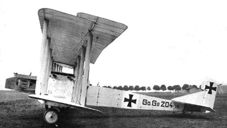
The Gotha G.II and G.III bombers made their appearance in 1916. The two bombers were remarkably similar, differing only in their engines and internal details. The G.II entered service in March of 1916 and was powered by a pair of direct drive 164kW six-cylinder liquid-cooled Mercedes DIV engines mounted in a pusher configuration. Some 15 G.IIs were used in the Balkans until they were withdrawn due to unreliable engines. Both aircraft were armed with two 7.92mm Maxim IMG Parabellum machine guns – one in the nose and another in the aft fuselage – and carried approximately 540kg of bombs. A few G.IIs and G.IIIs were equipped with a trapdoor in the undersurface of the rear fuselage, which permitted the rear gunner to take up a prone position and fire aft or downwards from a ventral position to defend the bomber’s vulnerable ‘blind spot.’ The G.II used straight-eight DIV engines of 220hp, the G.III straight-six DIVa’s with 260hp. Also the G.II did not have the trap-door, this was on G.IIIs only. Only 10 G.IIs were apparently built.
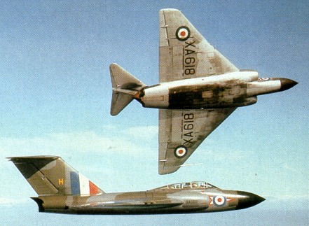
Designed to meet the requirements of Specification F.4/48 for a two-seat twin-engined all-weather interceptor fighter, the Javelin was of tailed-delta configuration and the first of seven prototypes was flown on 26 November 1951. The Javelin suffered a protracted development period, being subjected to delays arising from poor handling qualities and difficulties with integration of the radar.
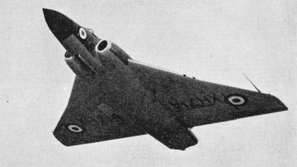
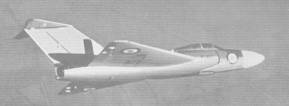
The third prototype, WT827, had a straight wing and early cockpit canopy. WT830, the fourth prototype, had a revised “cranked” leading edge giving a better fineness ratio over the ailerons, and also the old cockpit and no guns; and WT 836, the fifth prototype, which is to full production standard. This has a more extensive transparency over the rear cockpit with a streamlined fairing behind instead of the former rather abrupt cut off to the canopy. The fifth prototype also had the standard “cranked” wing and the full armament of four 30 mm cannon mounted just outboard of the angle in the leading edge.
It was not until late 22 July 1954 that the first production specimen made its maiden flight. This was the Javelin FAW.Mk 1, powered by two 3629kg Armstrong Siddeley Sapphire ASSa 6 turbojets and carrying an armament of four 30mm Aden cannon, which began to enter service with No. 46 Squadron in February 1956.
Forty F(AW) Mk Is for the RAF were followed by 30 F(AW) Mk 2s, the first example of this version flying on 31 October 1955.
The FAW.1 was su¬perseded in production by the Javelin FAW.Mk 2 which featured American (APQ 43) interception radar in place of the Brit¬ish (AI17) equipment originally fitted. Both of these models were armed with four 30-mm Aden cannon, as was the Javelin FAW.Mk 4 which intro¬duced an all-moving tailplane in an attempt to eliminate excessive stick force requirements when flying at high indicated speeds. First flown on 19 September 1955, differed in having a fully-powered all-moving tailplane, 50 being built.
The F(AW) Mk 4 paralleled production of 21 T Mk 3 dual-control trainers.
Additional fuel capacity in the wings and having provision for four de Havilland Firestreak AAMs was introduced in the Javelin FAW.Mk 5, which was otherwise virtually identical to the Javelin FAW.Mk 4, and both of these variants duly entered service during 1957. Sixty-four F(AW) Mk 5 were built.
The final ‘first-generation’ model was the Javelin FAW.Mk 6, which was basically a Javelin FAW.Mk 5 fitted with American radar. 33 F(AW) Mk 6s were built.
Whilst production of these was progressing, a major redesign effort had been initiated with the objective of installing the rather more powerful 4990kg Sapphire ASSa 7 200 series engine, and the first model to appear with this power-plant was the Javelin FAW.Mk 7, which also incorporated increased fuel capacity, Firestreak infra-red homing missiles modified flying controls, an extended rear fuselage with raised topline, and later interception equipment, though this entailed the loss of two Aden cannon. Armament comprised two 30mm Aden cannon and four Firestreak AAMs, and 142 were built. The Javelin FAW.Mk 7 took to the air for the first time in November 1956, deliveries get¬ting under way in August 1958.
The FAW.7 model was succeeded by the Javelin FAW.Mk 8 with US radar, drooped wing leading edges and a Sapphire ASSa 7R engines with limited afterburning boosting output to 5579kg above 6100m. Entering service with No. 41 Squadron during early 1960, the Javelin FAW.Mk 8 was the last new-build Javelin variant to appear. Forty-seven were built during 1957-60.
Production of the type terminating on 16 August 1960 when the 381st example made its initial flight.
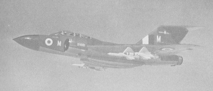
Subsequently 76 Javelin FAW.Mk 7s were updated to the definitive Javelin FAW.Mk 8 configuration, though retaining British radar, as Javelin FAW.Mk 9 aircraft standard during 1960-61, with Armstrong Siddeley Sapphire Sa.7R after-burning engines. It had a maximum speed of 702 mph and a service ceiling of 52000 feet. Armament was four Firestreak air-to-air missiles and two 30 mm Aden guns.
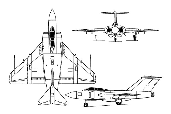
Javelin F.(A/W.) Mk.9
The Mk.9 having 28.5 degrees sweepback on the inner wings and 33.8 degrees on the outer section. Split flaps are under the wings and slotted-plate airbrakes above and below the wings, near the trailing edge, aft of the flaps.
The tricycle undercarriage has a single wheel on each unit. The mains retract inward into the wings and the nose wheel retracts rearward. They can have a flight-refuelling boom from the right side of the cockpit area.
Fuel tanks are in the wings and fuselage and can be supplemented by two 259 Imp.Gal tanks flush under the fuselage and up to four underwing tanks.
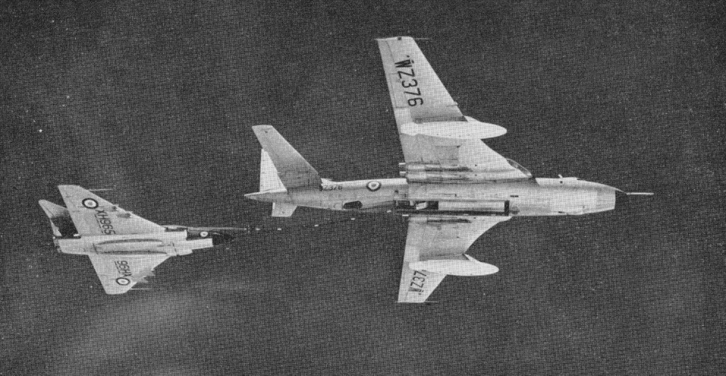
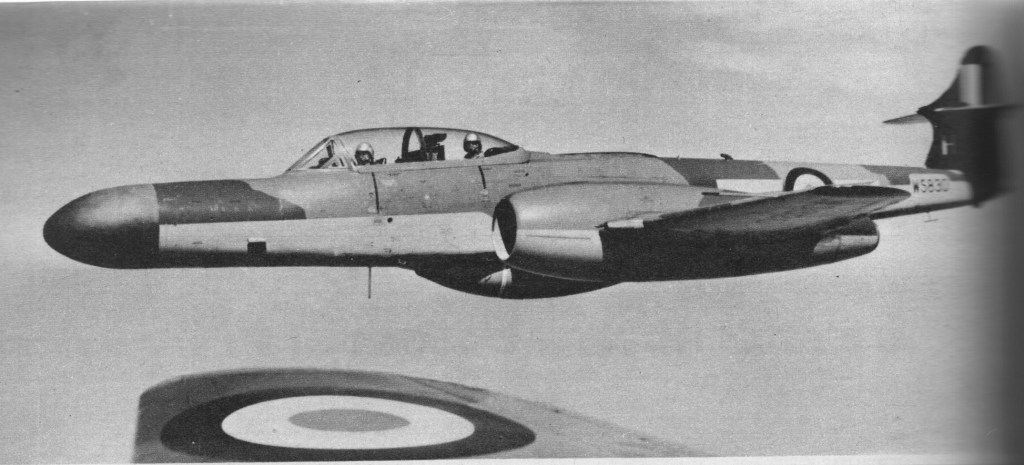
Late marks of Javelin were modified circa 1960 to accommodate aerial-refuelling equipment.
Javelin FAW.8 refuelling from a Vickers Valiant
The Javelin was finally withdrawn from RAF service in 1967.
Javelin F(AW). Mk 1 Engnes: 2 x Armstrong Siddeley Saphire ASSa.6 turbojets, 35.6kN Max take-off weight: 14324 kg / 31579 lb Wingspan: 15.85 m / 52 ft 0 in Length: 17.15 m / 56 ft 3 in Height: 4.88 m / 16 ft 0 in Wing area: 86.12 sq.m / 926.99 sq ft Max. speed: 1141 km/h / 709 mph Ceiling: 16000 m / 52500 ft Crew: 2
FAW Mk.8 Engines: two 5548-kg (12,230-lb) afterburning thrust Bristol Siddeley Sapphire Mk 203/204 turbojets. Maximum speed 1101 km/h (684 mph) at sea level Iinitial climb rate 3734 m (12,250 ft) per minute Service ceiling 15645 m (51,330 ft) Rnge with two 1137-litre (250-Imp gal) drop tanks 1497 km. (930 miles). Mximum take-off weight (40,000 lb). Wing span 15.85 m (52 ft 0 in) Legth 17.16 m (56 ft 3.5n) Hight 4.88 m (16 ft 0 in) Wing area 86.12 s (927 sq ft). Armament: two 30-mm Aden cannon, plus four Firestreak air-to-air missiles
Javelin F.(A/W.) Mk.9 Engines: 2 x Bristol Siddeley Sapphire 203/204, 12,300 lb with reheat Wingspan: 52 ft Wingarea: 928 sq.ft Length: 56 ft 4 in Height: 16 ft Wheel track: 23 ft 4 in Armament: 2 x 30 mm Aden cannon
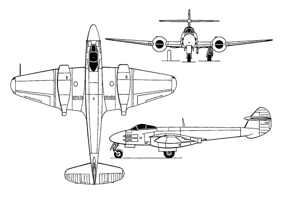
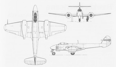
Designed by George Carter, the Gloster Meteor began life in response to Specification F 9/40, which called for a single-seat interceptor. The jet engine was still very much in its infancy when this project got under way and the low thrust available from early powerplants of this type necessitated the adoption of twin-engine layout from the outset. Under the impetus of war, design progress was swift and was rewarded with a contract for 12 prototypes in February 1941, although only eight of these prototypes were eventully completed.
The eight original F.9/40 airframes were used to test several different types of British gas turbines including the Rover-built Power Jets W2B, the parent design of the Rolls-Royce Welland with which the Meteor I was fitted; the Metropolitan Vickers F.2/1, the first British axial-flow unit to fly (13 November 1943); the Halford H.1, the predecessor to the de Havilland Goblin; and the Rolls-Royce Trent, the first turboshaft engine to fly. Actually the 6530kg Halford-engined F.9/40 was the first version of the Meteor to fly (on 5 March 1943) as the W2B engines (4360kg) installed in another F.9/40 in July 1942 were not ready for flying until June 1943.
The eight prototypes built (DG202 – DG209) were used for both airframe and powerplant development trials. Due to difficulties with supplies of the first jet engines the first flights of the prototypes were spread over several years with the last of them flying after the first F.Mk I’s were in service with the RAF.
Developmental aircraft –
DG202 First Flight: 24th July 1943 Rover W.2B/23 turbojets.
DG203 First Flight: November 1943 First flown in 1943 with two Power Jets W.2/500’s. Its next flight was almost a year later in October 1944 with more powerful W.2/700’s.
DG204 First Flight: 13th November 1943 Metropolitan-Vickers F.2, Axial-Flow turbojets, crashed 1st April 1944 after just 3 hours 9 minutes flying time.
DG205 First Flight: 12th June 1943 Rover W.2B/23’s, second to fly.
DG206 First Flight: 5th March, 1943 First to fly. de Havilland Halford H.1 turbojets (2,700 lbs thrust).
DG207 (prototype Meteor Mk II) First Flight: 24th July 1945 de Havilland H.1 Goblin, later became the prototype F. Mk II.
DG208 First Flight: 20th January 1944 First to be fitted with dive brakes and Rolls Royce W.2B/23 engines. Modified fin and rudder
DG209 First Flight: 18th April 1944 Early version of W.2B/37 Derwent I.
Although the first flight of a Meteor was with the de Havillands turbojet, production Meteors were powered by engines developed by Rover and later Rolls-Royce W.2B/23 Welland 1 reverse-flow turbojets with centrifugal-flow compressors, with the de Havilland engines allocated entirely to Vampire production which entered service shortly after the end of WW II. Trials with the Metropolitan-Vickers engines also were not wasted despite being cut short by the crash of DG204 and plagued by early problems as the F.2 developed into the successful Beryl turbojet and led directly to the Armstrong Siddeley Sapphire two of which were fitted to a Meteor making it the most powerful ever to fly.
The first of these began taxi trials with four types of engine in June 1942 but it was not until 5 March 1943 that the type took to the air for the first time, this maiden flight being made by the fifth prototype. By then, the Meteor had been ordered into production.
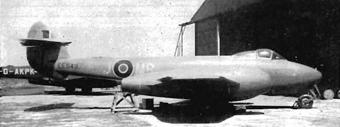
Only twenty Mk I’s were built, sixteen of them serving with RAF. Two of the three prototype Mk I’s EE211 & EE212 were delivered to RAE Farnborough for trials and design development, while the first EE210 (First flight 12th January 1944) was delivered to Muroc AFB in exchange for an example of the Bell X59 Airacomet.
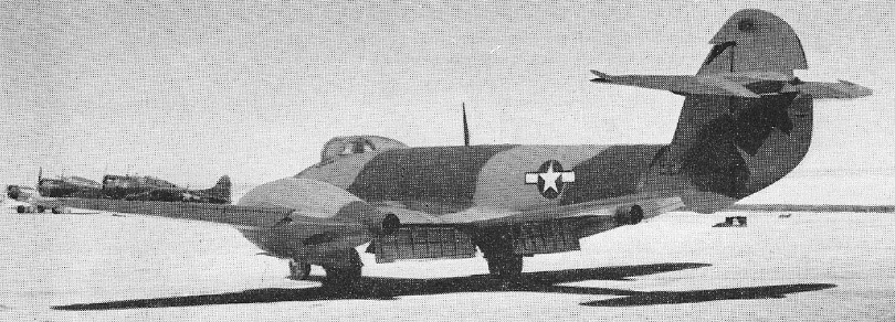
Gloster Meteor I EE210/G first production model at Muroc, Spring 1944
The /G (guard at all times) and prototype designation on the fuselage are still carried by DG202 at Cosford today. EE211/G was the second production Meteor, an F.Mk 1. Armed with four 20-mm cannon andpowered by two Wellan d I turbojets, it could reach a speed of 668 km/h (415 mph). Meteors provided good training for American bomber crews now faced with attacks from Me 262s.
616 Squadron at Cultrihead took delivery of the next ten EE213 – EE222 and the four aircraft EE224 – EE227 in July 1944. The last two deliveries EE228 & EE229 being attrition replacements for EE224 & EE226 with the latter crashing just two days after delivery. The first took delivery of the Meteors at Culmhead on the 12th July 1944 moving shortly afterwards to Manston in Kent where they started operations against the V1 flying bombs.
The squadron then moved to Manston where they would later take the Meteor into Europe although they were prohibited from flying over enemy lines because of the secrecy of the materials used in the engines. At 2.30pm on Thursday 27 July 1944, an RAF Gloster Meteor of No.616 (South Yorkshire) Squadron left its airbase at Manston, Kent, to make its first anti-V-1 patrol flight over the Channel, but it met no flying bombs. Shortly after, two more Meteors took off, and Sqn.Ldr. Watts saw a V-1, overtook it near Ashford, and pressed the firing button; but the guns jammed and the V-1 got away
On 4 August 1944 Meteor III won its first aerial victory, when Flt.Lt. P.J. Dean met a V-1 flying bomb about 3.5 miles south of Tonbridge, Kent. His Meteor cannon jammed repeatedly, so he knocked the flying bomb off course with his wings and made it crash. Several minutes later a second Meteor pilot, Fl.Off. J.K. Roger, reported that he too had downed a V-1 near Tenterden, Kent. Starting 11 August, 616 kept two Meteors on patrol duty throughout the day; each pair would patrol for 30 minutes while two more waited to take off and replace them. The squadron later moved to Belgium where it was joined by No. 504 Squadron with Meteor Mk III aircraft, also with Welland engines, but fitted with sliding hoods.
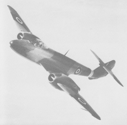
Meteor F.III EE245 No.15 Sqn Derwent engines
A Meteor was also used in the first tests of a ground level ejection seat. The production Meteor F.1 was powered by two 7400kg Rolls-Royce Welland 1 turbojet engines and had a cockpit canopy that was side-hinged.
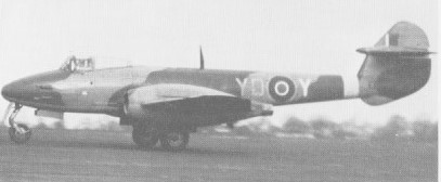
Meteor F.I of 616 Sqn July 1944
At RAE Farnborough EE211 was fitted with a pair of Powerjets W2/700’s and long cord engine nacelles which improved its high speed performance while at Rolls Royce EE223 in addition to being the first Mk 1 to have a pressure cabin for high altitude flight was also fitted with the more powerful W2B/37 Derwent I’s. The most interesting developmental Mk I was EE227, on its retirement by 616 Squadron in favour of the Meteor Mk III it became the world’s first turboprop, powered by a pair of Rolls Royce Trent’s.
The only Meteor F Mk II was the prototype based on DG207, also designated the G.41B it was powered by two DH Halford H.1 engines but did not enter production because its H1 engines (later known as the Goblin) were instead allocated to DH Vampire production following greater success with the W2/B Welland & Derwent designs after Rolls Royce became involved in engine production.
The first volume production version of the Meteor was the Mk III (G.41C) with a total of 210 aircraft built. Similar to the MK I except for the new sliding Malcolm canopy and slotted airbrakes it had a strengthened airframe to absorb the additional power from the 2,000 lb thrust Derwent I engines. Due to production difficulties the first 15 had to make do with W.2B/23 Welland engines although some of these aircraft may have been retrofitted later once sufficient engines were available. These early aircraft almost all operated by 616 Squadron can be distinquished from the Derwent powered Meteors due to their slightly longer jet-pipe which protruded from the rear of the nacelle to a greater extent.
The Meteor F.Mk III saw operational service with 504 Squadron as well, being mainly em¬ployed in ground attack duties, but only a few of the 280 Meteor F.Mk IIIs built had entered service by VE-Day. Many of the first Meteor F. Mk III deliveries were painted white. This may have been an effort to prevent the Meteor from being mis¬taken for a German jet, as was the only No.616 Sqn Meteor F. Mk 1 to be shot at in the first three months (by a Spitfire).
The standard engines were two 8720kg Rolls-Royce Derwent Is, although the first 15 Mk 3s were fitted with Wellands. Sliding cockpit hoods were standard and provision was made for a long-range fuselage drop tank. The last 15 F.3s were fitted with the lengthened engine nacelles standardised on the Mk 4.
Many F Mk III’s were used in aviation research either directly from the Gloster production line or after squadron service including EE416 which went to Martin-Baker for ejection seat trials. Two others were fitted with strengthened undercarriage and a V Frame arrestor hook for deck landing trials on HMS Immplacable.
One of the thirty F Mk. III’s allocated for tests and trials showed the benefit of increasing the chord (length) of the engine nacelles. With the longer nacelles there was less compressibility buffetting at high speeds leading to an increase in the redline speed at 30,000 ft of 75 mph. As a result of these tests the last fifteen F Mk. III’s were delivered with longer nacelles. The increased power of the Derwent engine and this performance improvement led directly to the Meteor F4 and its successful attempt at the world absolute air speed record.
Two F Mk III’s were evaluated by foreign air forces with Mk III, EE311 going to the RCAF although it didn’t last long, running out of fuel and being ditched in June 1946. The second aircraft was operated for some years by the RNZAF. Re-serialled NZ6001 it was demonstrated throughout New Zealand from late in 1945 and eventually purchased for £5,000. It later became an instructional airframe and was scrapped in 1957.
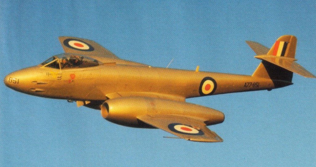
In May 1946 a F.3 Meteor was taken on charge by the Royal Australian Air Force, becoming the first RAAF jet fighter. It was not until 1951 that Meteors entered regular service with the RAAF and then they did so with a true “baptism of fire”. Meteor F.8 aircraft were taken into action by 77 Squadron RAAF, in Korea, against the Mig-15.
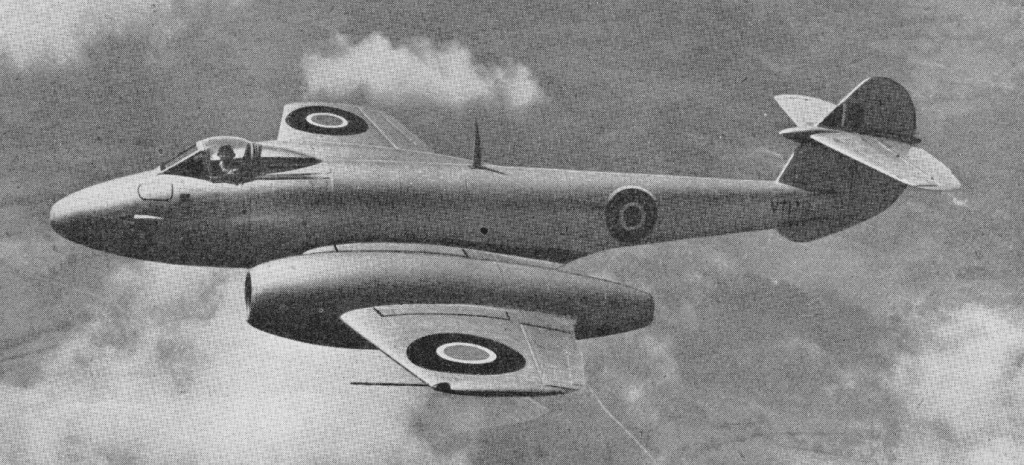
Production then switched to the Meteor F.Mk 4 with much more powerful engines, 583 being built be-tween 1945 and 1950.The first example flying on 12 April 1945. Power was provided by two Derwent 5 engines and the wing span was reduced to 11.33m to improve the rate of roll. Other features included long engine nacelles, pressure cabin, and fittings for bombs and rocket projectiles. An aircraft of this version set up world speed records on 7 November 1945 and 7 September 1946, flown by Group Captain E. M. Donaldson, of 975km/h and 991km/h respectively.
The Meteor 4 once used by Air Chief Marshal Sir James Robbs as his personal aircraft.
The private venture Meteor T.7 was a two-seat training version of the Mk 4, with the forward fuselage lengthened by 0.76m to accommodate tandem cockpits under a continuous canopy. No armament was carried. The first T.7 flew on 19 March 1948 and over 600 were built.
In the markings of the Brazilian Air Force, Meteor 7s were used in Britain to train Brazilian pilots. Brazil purchased 70 Meteor fighters and trainers.
Brazilian Gloster Meteor 7s
The F.8 was the most built of all Meteors with 1,522 being produced, first flown on 12 October 1948.
F.8
The F.8 differed in having a lengthened fuselage, redesigned cockpit and tail assembly.
The F.8 established international point-to-point records on London-Copenhagen, Copenhagen-London and London-Copenhagen-London in 1950 and in the following year set up a new international speed record over a 1,000km closed circuit of 822.2km/h.
The FR.9 and PR.10 were fighter-reconnaissance and unarmed photo- reconnaissance variants, the PR.10 having a similar nose and cockpit to the FR.9 but a 43 ft wingspan and an F.4 tail.
By 1950 the Meteor F.Mk 8 was well established in service, this model also being built under licence in Belgium and the Netherlands, embracing powerful Derwent engines, modified cockpit and canopy. 1090 F.8s were built.
Other single-seater variants included the Meteor FR.Mk 9 fighter-reconnaissance version of the Mk 8, and Meteor PR.Mk 10 unarmed version for high-altitude reconnaissance aircraft.
In addition to seeing widespread service as a day fighter, the Meteor also successfully adapted to night-fighter tasks, albeit as a two-seater. The initial variant engaged in this mission was the Meteor NF.Mk 11, the design of which was undertaken by Armstrong Whitworth was first flown in May 1950. The NF.11 had the longer span wing of the photo-reconnaissance Meteor, a lengthened nose to house the radar, tandem cockpits, and the tail of the F.8 day fighter. The four 20mm guns were transferred outboard of the nacelles. The NF.11 weighed about 14 ton at MAUW which included 700 gallons of fuel, two integral tanks of 375 gallons, an external ventral of 175 gallon, usually permanently fitted and two 100 gallon wing tanks. The NF.11 being succeeded by the Meteor NF.Mk 12 of April 1953 had a lengthened nose and improved radar, and a faired tail bullet which effectively increased fin area with a different radar, the NF.Mk 13 with tropical equipment, and the Meteor NF.Mk 14 was tested late in 1953 with a clear-vision canopy and other refinements.
The Meteor NF.14 Night Fighter was the last major development of the line. The NF.14 was a two-seat, twin-engined monoplane, powered by two Rolls-Royce Derwent 8 turbojets, each delivering 3,600 lb thrust. The service ceiling was 40,000 feet and the maximum speed was 579 mph. Its range, with ventral and underwing tanks, was approximately 950 miles at altitude. A ventral fuel tank was normally carried and two under-wing tanks of 100 Imp.Gal. were optional.
Meteor night-fighters were used for experimental launching of guided missiles.
Night-fighter production by Armstrong Whitworth totalling 547 aircraft.
Production of night-fighter variants eventually totalled 578, some later being modified for target towing duty as the Meteor TT.Mk 20 whilst many single-seaters served as Meteor U.Mk 15, Meteor U.Mk 16 and Meteor U.Mk 21 drones developed by Flight Refuelling Ltd.
The Meteor proved a success and over a thousand of the new fighters were built to re-equip twenty Fighter Command squadrons and ten squadrons of the Royal Auxiliary Air Force.
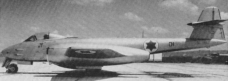
A total of 3,545 Meteors was produced by Gloster and Armstrong Whitworth., more than 1,100 of which were F.8s. Meteors were also exported in considerable numbers for service with the armed forces of Argentina, Australia, Belgium, Brazil, Denmark, Ecuador, Egypt, France, Israel, the Netherlands and Syria.
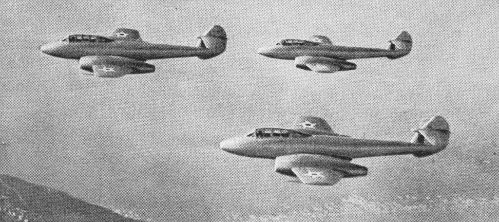
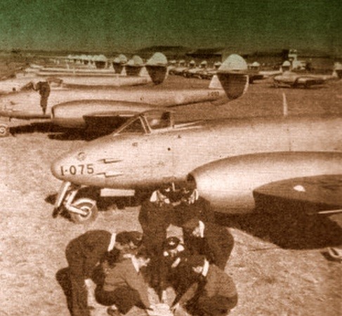
Argentine Meteors
Part of the group of Gloster Meteors that Argentina bought from England in the beginning of the 1950s to serve as interceptors. The Air Force ordered 100 F4, 50 were ex-RAF, 50 were new. It was due to a large debt that England owed to Argentina that the airplanes were acquired. England could not pay the debt outright so arrangements were made for the airplanes.
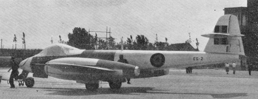
The Fokker assembled Meteor 8 (the first from British parts) were powered by Rolls-Royce Derwent 8s built in Belgium.
First Fokker assembled Meteor 8
By July 1950 production of 300 Meteor 8, to be evenly divided between the Dutch and Belgian Air Forces was underway at Fokker.
Two Belgian Meteor 8 and a Dutch Meteor 4 at Schiphol
To investigate a prone piloting position a Meteor F.8 was converted by Armstrong Whitworth circa 1955 to feature a prone position in a special elongated nose. Aft is a normal cockpit with a safety pilot. The prone-pilot Meteor was flown extensively from Baginton and Farnborough.
G.41 Meteor F. I Engines: two 771-kg (1,700-lb) thrust Rolls-Royce Welland 1 turbojets Maximum speed: 668 km/h (415 mph) at 3050 m (10,000ft) Service ceiling: 12190 m (40,000 ft) Empty weight: 3692 kg (8,140 lb) Maximum take-off weight: 6257 kg (13,795 lb) Wingspan: 13.11 m (43 ft 0 in) Length: 12.57 m (41 ft 3 in) Height: 3.96 m (13 ft 0 in.) Wing area: 34.74 sq.m (374.0 sq ft) Armament: four nose-mounted 20-mm Hispano cannon (provision for six) Crew: 1
Gloster G. 41 Meteor F.I Engines: 2 x Rolls Royce W.2B/23C Welland, 7564 N / 771 kp Length: 41.24 ft / 12.57 m Height: 12.992 ft / 3.96 m Wingspan: 43.012 ft / 13.11 m Wing area: 373.941 sq.ft / 34.74 sq.m Max take off weight: 13796.7 lb / 6257.0 kg Weight empty: 8140.9 lb / 3692.0 kg Max. speed: 361 kts / 668 km/h Service ceiling: 39993 ft / 12190 m Wing loading: 36.9 lb/sq.ft / 180.0 kg/sq.m Range: 1164 nm / 2156 km Crew: 1 Armament: 4x 20mm MG
Meteor F.III Engines: 2 x 2,000lb Rolls Royce Derwent IV Turbojets Span: 43ft Length: 41ft 3in. MAUW: 14,750 lb Maximum speed: 415mph at 30,000ft Service Ceiling: 40,000ft Rate of Climb: 3,300ft/min Range: 510 miles Armament: 4 x 20mm Hispano cannon
F.4 Engines: 2 x Rolls-Royce Welland, 1700 lb. Wing span: 37 ft 2 in (11.33 m). Length: 41 ft 4 in (12.6 m). Height: 13 ft 0 in (3.96 m). Max TO wt: 15,175 lb (6883 kg). Max level speed: 585 mph ( 941 kph).
F.8 Engines: 2 x 1633-kg (3,600-lb) thrust Rolls-Royce Derwent RD.8 turbojets. Wingspan 11.33 m (37 ft 2 in) Wing area 32.52 sq.m (350 sq ft) Length 13.26 m (42 ft 6 in) Height 4.22 m (13 ft l0 in) Empty weight 4846 kg(10,684 lb) Maximum take-off 7836 kg (17,275 lb) Fuselage Tank Capacity: 330 Imp Gal / 1,500 lt / 396 U.S. Gallons Ventral Tank Capacity: 175 Imperial Gallons / 796 Litres / 210 U.S.Gallons Maximum speed 953 km/h (592 mph) at sea level Initial climb rate 2134 m (7,000 ft) per minute Service ceiling 13410 m (44,000 ft) Range, clean 1110 km (690 miles) Range: 767 mi at 40,000 ft Armament: four 20-mm Hispano Mk V cannon / Two 1000lb (455 kg) bombs or eight 60 lb (27.3 kg) air to ground rockets. Wheel track: 19 ft 5 in Wheelbase: 13 ft 4 in
PR.10 Engines: 2 x Rolls-Royce Derwent R.D.8, 3600 lb Wingspan: 43 ft Length: 43 ft 6 in Height: 13 ft 10 in Wing area: 350 sq ft
NF.11 Engine: 2 x Rolls-Royce Derwent, 3500 lb. Fuel cap: 375 internal (+375 external) Imp.Gal. Armament: 4 x 20mm Hispano cannon. Max speed: 520 kts (430 kts with wing tanks).
Meteor NF.14 Engines: 2 x Rolls-Royce Dewent Span: 43 ft Length: 49 ft 11 in MAUW: 20,000 lb approx Max speed: 590 mph approx
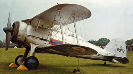
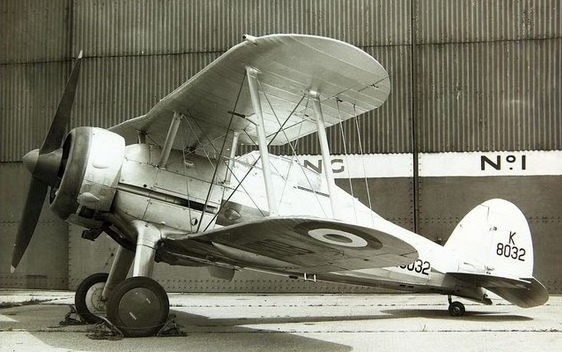
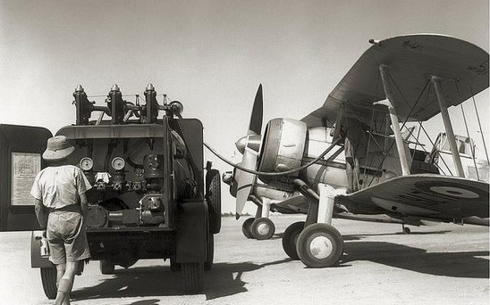
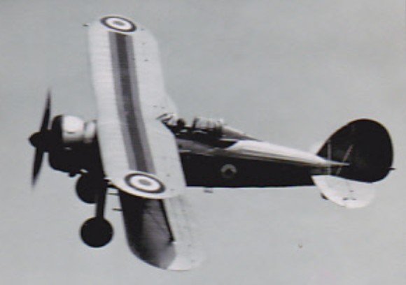
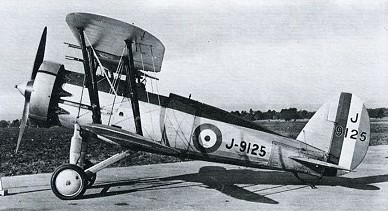
An improved version of the high-performance Gauntlet, in the Gloster SS.37Gladiator H. P. Folland endeavoured to satisfy the requirement of the Air Ministry’s F.7/30 specification which the Gauntlet had failed to meet. However the Gauntlet’s maximum speed was some 32km/h below the F.7/30 requirement, which also called for an offensive armament of four machine-guns. The Gauntlet represented a close approach to the requirement and Folland decided that aerodynamic improvements of the basic Gauntlet fuselage (together with installation of a more powerful engine) should prove adequate for the Gloster design to be ordered into production. It had been intimated by the Air Ministry that submissions for the F.7/30 requirement which were powered by the new Rolls-Royce Goshawk evaporative-cooled engine would receive favourable consideration. This meant that of the seven other contenders for this contract, five were designed to utilise the Goshawk. When this engine failed, it eliminated most of Gloster’s competitors. Folland pinned his hopes on the Bristol Mercury ME.30 radial which was then promising a power output of some 521.6kW. But it was not available when the prototype SS.37 was nearing completion and the first flight, on 12 September 1934, was made with an 840 hp / 395kW Mercury IV. The prototype Gladiator had an open cockpit, no gyro instruments and only 645 hp; the production airplane had a greenhouse that you closed by winding it forward by means of a bicycle chain and sprocket arrangement.
Features included each of the four planes having small hydraulically depressed drag flaps and cantilever landing gear with Dowty internally sprung wheels. Most early production had the Watts wooden propeller, though performance was better with the three-blade metal Fairey-Reed type.
On 1 July 1935 the Air Ministry ordered 23 aircraft in July 1935, as Gladiators, one going to Greece. These were powered by the 618.5kW Bristol Mercury IX. Other improvements included an enclosed cockpit with a sliding canopy and a redesigned tail unit.
It introduced refinements such as wing flaps and cantilever undercarriage which enabled it to combine a top speed of 253 mph but the maximum speed, between 174 and 217 knots, was slower than those of the newest bombers. The armament was four .303 Browning machine guns (two, engine synchro¬nized, in cutaways in the fuselage sides, and two in blisters under the lower wings) was inadequate. Metal structure, fab¬ric covered, no armor plate, no self-¬seal around the fuel tanks and no proper fire wall behind the engine.
It first entered service with Nos. 3 and 72 Squadrons in January 1937 as a replacement for the Bulldog. The early Gladiator I were followed by an improved Gladiator II in 1938 powered by the Bristol Mercury VIIIA engine. Other improvements comprised the addition of a battery and electric starter and the inclusion of a full blind-flying instrument panel.
Production also included 60 Sea Gladiators for the FAA. Generally similar to the Gladiator II, they differed by being equipped for catapult launch and deck landing – although not intended for operational use from carriers – and carried an inflatable dinghy in a fairing beneath the lower wing centre-section.
When World War II began, in 1939, the RAF still had 13 Gladiator squad¬rons; one home squadron was still fly¬ing them when the Battle of Britain started in 1940. Production of the type finished that year, but two squadrons went to France with the Advanced Air Striking Force in 1939.
In just ten days of hard fighting, following the opening of the German assault on 10 May 1940, all the aircraft had been lost. In a desperate attempt to provide fighter cover for the ‘little ships’ involved in the Dunkirk evacuation a detachment of home based aircraft, known as ‘G’ Flight, was formed at RAF Manston in late May. One squadron (No. 247) served during the Battle of Britain. In Norway during April, May and June the Gladiator, flown by Pilots of No. 263 Squadron from a frozen lake, offered opposition to the Luftwaffe forces supporting the German invasion of that country, fighting on until all its aircraft had been destroyed in the air or on the ground. Only two home based units used the Gladiator operationally during the Battle of Britain; No.247 Squadron at RAF Exeter and RAF Roborough and No.804 Squadron, Fleet Air Arm at stations in Scotland. A flight of four Sea Gladiators, flown by RAF pilots, defended Malta with such success that the Maltese named three of them Faith, Hope and Charity and, after the war, preserved one as a reminder.
The last biplane fighter to serve with the RAF and Royal Navy, of the total 747 Gladiators which were built, almost 30% were exported, serving with the armed forces of Belgium, China, Finland, Greece, Iraq, Irish Republic, Latvia, Lithuania, Portugal, Norway and Sweden. In addition some aircraft transferred from the RAF operated with Egyptian and South African forces.
After the Russian invasion of Finland in 1940, slowly reinforcements began to arrive for the Finnish air force. The first to come were 5 Gloster Gladiators, 12 Hurricanes, 17 Lysanders and 24 Blenheims, all from Britain. After that, 76 Morane-Saulnier and Koolhoven F.K. fighters arrived from France. Italy sent 17 Fiat fighters, Sweden 12 Gloster Gladiators, and the USA 44 Brewster Buffalo, of which however only 5 reached Finland in time. Even the Union of South Africa sent 25 Gloster Gladiators. Pilots and ground personnel from a number of countries also volunteered to assist them.
At the peak of its deployment the Gladiator was flown by 29 home and 11 overseas squadrons and many remained in RAF service until early 1945.
Total production amounted to at least 767, including 480 for the RAF, 60 Sea Gladiators and 216 exported to 12 countries. The last delivered in May 1940.
Latvia model
Users were Belgium, China, Egypt, Finland, Greece, Iraq, Ireland, Latvia, Lithuania, Norway, Portugal, South Africa, Sweden, and the RAF and RN.
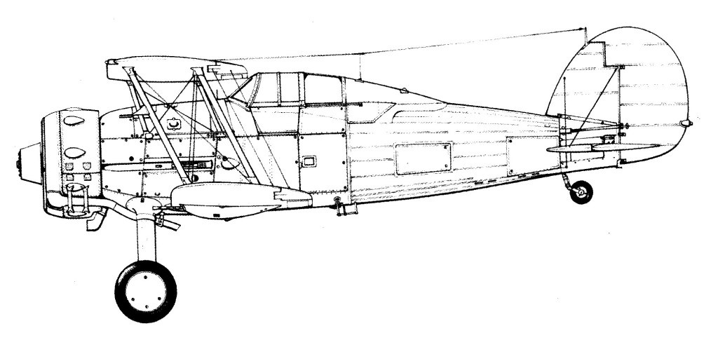
Gladiator I Engine: Bristol Mercury IX or IXS Wingspan: 32 ft 3 in / 9.85 m Length: 27 ft 5 in / 8.38 m Height: 10 ft 4 in / 3.17 m Empty weight: 3450 lb / 1565 kg Loaded weight: 4750 lb / 2155 kg Max speed: 253 mph / 407 kph ROC: 2300 fpm / 700 m/min Service ceiling: 33,999 ft / 10,060 ft Range: 440 mi / 708 km Armament: first 71 aircraft 2 x 0.303in Vickers in fuselage, 2 x 0.303in Lewis lower wings, subsequent 4 x 0.303in Browning in same locations. 600 rounds each in fuselage, 400 in wings
Sea Gladiator Empty weight: 3475 lb Loaded weight: 5420 lb Max speed: 245 mph Range: 425 mi
Gloster SS 37 Gladiator Mk. II Engine: Bristol Mercury IX, 840 hp / 620kW Prop: 10ft 9in dia Watts two blade fixed pitch wooden MAUW: 4,750 lb. Empty weight: 3,450 lb. (1,565 kg). Wingspan: 9.8 m / 32 ft 2 in Length: 8.4 m / 27 ft 7 in Height: 3.2 m / 10 ft 6 in Wing area: 30.0 sq.m / 322.92 sq ft Max speed: 213 kts/253 mph at 15,000 ft. Ceiling: 7500 m / 24600 ft ROC: 2,450 fpm. Endurance: 2hr at 210 mph. Fuel cap: 100 (U.S.) gallons. Range: 400 miles. Crew: 1 Armament: 4x .303 MG (7,7mm)
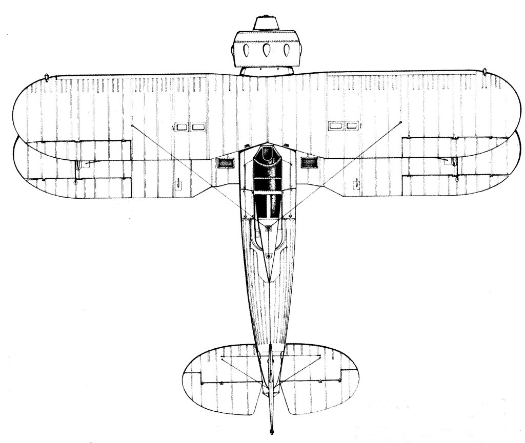
Specifications F.9/26 and F.20/27 remained unfulfilled; and F.7/30 calling for a 402km/h four-gun fighter seemed initially even more unlikely to be attained. Gloster’s first submission had been an improved version of the all-metal Goldfinch, and with the progression of time this design had been subjected to several permutations of airframe innovations and differing engines. When, in 1933, Gloster’s SS.19B demonstrated a maximum speed of 346km/h during tests at Martlesham Heath, it was ordered into production under the name Gauntlet I. During the period 1935 to 1937 Gauntlets were the fastest fighters in RAF service, partially replaced by Gladiators and Hurricanes in 1938 and finally ousted by Spitfires in 1939. Aircraft produced from 1935, after Hawker Aircraft had taken over the Gloster company, were constructed according to Hawker production methods, bringing changes to wing spar and fuselage structure. These differing aircraft were designated Gauntlet II.
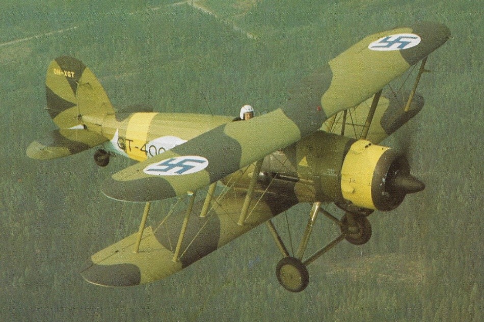
Gloster Gauntlet Mk.II GT-400
Last open-cockpit biplane in RAF service, the Gauntlet equipped 14 squadrons at its peak period of usage. It was during this same period that a very different performance was given under most secret conditions when (in November 1936) three of No 32 Squadron’s Gauntlets intercepted a civil airliner under the guidance of an experimental ground-radar installation at Bawdsey Manor, Suffolk. Thus the Gauntlet has the distinction of carrying out the world’s first radar-controlled interception.
Gloster SS 19 B Gauntlet Engine: Bristol Mercury VI S.2, 631 hp Length: 26.411 ft / 8.05 m Height: 10.236 ft / 3.12 m Wingspan: 32.776 ft / 9.99 m Wing area: 314.955 sq.ft / 29.26 sq.m Max take off weight: 3971.2 lb / 1801.0 kg Weight empty: 2769.5 lb / 1256.0 kg Max. speed: 200 kts / 370 km/h Service ceiling: 33497 ft / 10210 m Wing load: 12.71 lb/sq.ft / 62.0 kg/sq.m Range: 400 nm / 740 km Crew: 1 Armament: 2x cal.303 MG Vickers (7,7mm)
Gauntlet Mk II Engine: 1 x Bristol Mercury VIS2, 477kW Max take-off weight: 1801 kg / 3971 lb Empty weight: 1256 kg / 2769 lb Wingspan: 9.99 m / 32 ft 9 in Length: 8.05 m / 26 ft 5 in Height: 3.12 m / 10 ft 3 in Wing area: 29.26 sq.m / 314.95 sq ft Max. speed: 370 km/h / 230 mph Ceiling: 10210 m / 33500 ft Range: 740 km / 460 miles Armament: 2 x 7.7mm machine-guns
In 1923 Gloster built a two-seat private-venture research aircraft which became known as the Grouse, to carry out flight evaluation of new and special biplane wings. Simultaneously a single-seat version was built. When demonstrated to Air Ministry officials, its performance was considered to be so impressive that three prototypes were ordered. The first of these became the Grebe prototype which, following evaluation, was ordered into production under the designation Grebe II. This differed from the two-seat version by having a more powerful Jaguar IV engine (instead of a Jaguar III) and several other modifications.
The Grebe entered service in October 1923 with the RAF’s No 111 Squadron, and total production numbered 113 aircraft, including a small number of two-seat dual-control trainers. The Grebe was found to have wing flutter problems, resulting in the addition of outward-sloping Vee struts to brace the overhang of the upper wing. Two Grebes were modified during 1926 with special release attachments on the top surface of the upper wing. This allowed them to be carried into the air beneath the keel of the British rigid airship R-33, and used for launching experiments.
Grebes remained in service until their replacement by Armstrong Whitworth Siskins in mid-1928.
Grebe Mk II Engine: 1 x Armstrong Siddeley Jaguar IV, 385-425 hp Max take-off weight: 1189 kg / 2621 lb Empty weight: 780 kg / 1720 lb Wingspan: 8.94 m / 29 ft 4 in Length: 6.17 m / 20 ft 3 in Height: 2.82 m / 9 ft 3 in Wing area: 23.60 sq.m / 254.03 sq ft Max. speed: 243 km/h / 151 mph @ SL Ceiling: 7010 m / 23000 ft Armament: 4 x 7.7mm forward-firing machine-guns Crew: 1
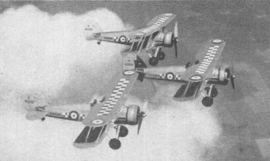
A development of the Gloster Grebe fighter, the Gamecock was initially to Specification 37/23, a re-engined variant of the Grebe using the new 398hp Bristol Jupiter IV radial engine. Of wooden construction with fabric skinning and retaining the then-standard armament of two synchronised 7.7mm Vickers guns. Ordered originally as the Grebe II in August 1924, the prototype Gamecock 1 (as it became titled) was delivered to Martlesham Heath for service tests on 20 February 1925. Trial reports were enthusiastic, resulting in an initial order for 30 production Gamecock Is machines in September 1925 powered by the 425hp Jupiter VI. First to take delivery of the production Gamecocks was 23 Squadron RAF, at Hen¬low, in May 1926; followed by 3, 17, 32 and 43 Squadrons. Although designed for day fighting, the Gamecocks issued to 3 and 17 Squadrons were specially modified for night interception duties. During the next five years, Gamecocks were prominent in the many public displays organized by the RAF, and demonstrated the type’s manoeuvrability in many superb aerobatic exhibitions. A further 60 Gamecock Is were built for the RAF (1925-27), one of these (unofficially known as the Gamecock III) at one time flying with a lengthened fuselage, new and enlarged fin-and-rudder assembly and narrow-chord ailerons.
Gamecock II
The Gamecock recorded a relatively high accident rate in service use; 22 having crashed within 19 months of its introduction to the RAF, and killing eight pilots. A variety of modifications were embodied progressively to eliminate the Gamecocks’ tendencies to spin abruptly and give wing flutter at high speed. Despite such characteristics, service Gamecocks quickly demonstrated their fast performance by tak¬ing the first three places in the 1927 Sassoon Cup Race for RAF fighter squadrons. A developed version, the Gamecock II, with a steel-tube upper wing centre section, narrow-chord ailerons and a larger rudder, appeared in 1928. This was adopted by Finland, two pattern aircraft and a manufacturing licence being acquired. Fifteen Gamecock IIs were built for the Finnish air arm 1929-30 by the State Aircraft Factory (Valtion Lentokonenetehdas), these having the lengthened fuselage tested earlier in the UK by the so-called Gamecock III and being powered initially by the 420hp Gnome-Rhone Jupiter (IV) 9Ab or 9Ak and later by the 480hp Jupiter (IV) 9Ag. By 1929 licensed production of the design (renamed Kukko) began at Helsinki. One unit, Fighter Squad¬ron 24, continued to fly this variant from 1929 until 1935; while one Finnish Gamecock (GA¬46) remained in service until late 1944.
Though development of the basic Gamecock was undertaken, resulting in the Gamecock II and III, the latter saw no service use. In 1928 the Finnish government, having been much impressed by various dis-plays of the Gamecock’s versatility, placed an order for the type.
Last of the all wood construction fighters in RAF use, the Gamecock achieved fame in perpetuity when the reformed 43 Squadron adopted a fighting cock as its chosen official badge motif; the unit being known ever since as ‘The Fighting Cocks’.
The last Gamecock Is were withdrawn from first-line RAF service mid-1931, Gamecock IIs remaining first-line Finnish equipment until 1935. In total 108 were built.
Gamecock Mk I Engine: 1 x Bristol Jupiter VI, 317kW Max take-off weight: 1299 kg / 2864 lb Empty weight: 875 kg / 1929 lb Span: (upper) 9.07 m (29 ft 9.5 in) Spun (lower) 7.89 m (25 ft 11 in) Length: 5.99 m / 19 ft 8 in Height: 3.06 m / 10 ft 0 in Wing area: 34.63 sq.m / 372.75 sq ft Max. speed: 249 km/h / 155 mph Ceiling: 6736 m / 22100 ft Armament: 2 x 0.303 in (7.7 mm) Vickers Mk 1, 1200 rounds. Endurance: 2.5 hr at 4572 m (15000 ft)
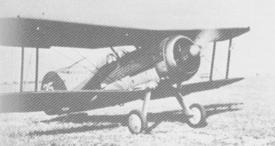
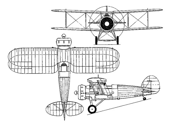
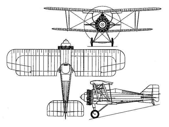
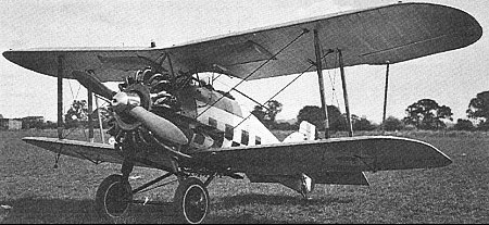
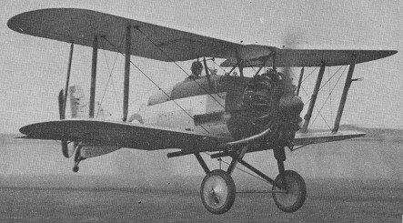
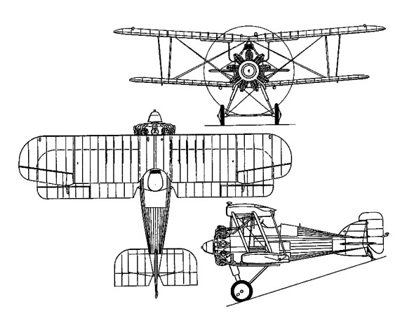
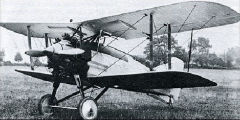
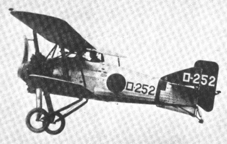
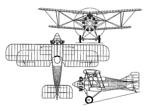
During 1926, in which year Gloucestershire Aircraft changed its name to Gloster Aircraft, the company was approached by the Japanese Nakajima, which (together with Aichi and Mitsubishi) had been asked to submit a design for a new shipboard fighter for the Imperial Japanese Navy. At this time, H P Folland was designing a shipboard fighter as a company venture. Named Gambet, the prototype was of wooden construction and powered by a 420hp Bristol Jupiter VI nine-cylinder radial, armament consisting of two 7.7rnm Vickers guns mounted in troughs in the fuselage sides. This prototype was acquired by Nakajima in July 1927, together with manufacturing rights. After modification by a team led by Takao Yoshida and installation of a 520hp Nakajima built Jupiter VI engine, the Gambet competed against prototypes of indigenous design and was ordered into production in April 1929 as the Navy Type 3 Carrier Fighter (A1N1).
Nakajima A1N1-2
Engine: 1 x Bristol Jupiter VI, 313kW Max take-off weight: 1395 kg / 3075 lb Empty weight: 912 kg / 2011 lb Wingspan: 9.70 m / 31 ft 10 in Length: 6.49 m / 21 ft 4 in Height: 3.25 m / 10 ft 8 in Wing area: 26.38 sq.m / 283.95 sq ft Max. speed: 245 km/h / 152 mph Ceiling: 7070 m / 23200 ft
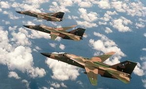
During the 1950s, the general development of tactical aircraft moved in the direction of greater performance, at the expense of long field length, high cost and inflexibility. By 1959, USAF Tactical Air Command was ready to plan a new aircraft, in the first instance to replace the F 105, which would combine many new features and offer outstanding capability and versatility. In particular, it would be the first combat aircraft to have a variable sweep (so called ‘swing wing’) aerofoil to match the conflicting needs of high lift at takeoff or landing, low speed efficiency in subsonic cruise or loiter, and minimum-area minimum span shape for low level attack at the highest possible speed.
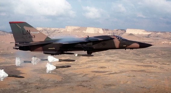
What caused great difficulty was that, in the first place, the TAC planners set their sights too high in drafting Specific Operational Requirement 183, so that the figures could not be met. Second, the US Navy in 1959 also wanted an important new aircraft, a Fleet Air Defense Fighter, carrying a powerful radar and long range missiles. In 1960, the new Secretary for Defense, Robert S McNarnara, studied the two requirements and, in his words, ‘was struck by the high degree of similarity’. After discussion with his civilian aides, he decided to urge that the USAF and Navy work towards a common aircraft design. His advisors suggested that such a move, called ‘commonality’, would save a billion dollars. After the longest and most hard fought procurement battle in history, General Dynamics Fort Worth won over Boeing¬ Wichita, the choice being announced on November 24, 1962. There had been an unprecedented four rounds of detailed technical and cost bidding, and in each round the consensus of customer opinion had, it was claimed, favoured Boeing. The Wichita team had not only offered what was in some respects a superior product, but they had consistently quoted a lower price. After Pentagon adjustments, the quotation for research, development and production of a total of 1726 aircraft (231 of them to be of the navy version) by Boeing was $5387 million and that from GD was $5803 million. As soon as the decision was announced, there was a storm of protest in Washington. It grew, as there was a prolonged public enquiry, and the position was later exacerbated by trouble with the winning aircraft and consistent failure to meet the impossible specification. GD flew the first F 111A on December 21, 1965, and on the second flight operated the wings through the whole range of sweep, from 16 degrees to 72.5 degrees, ahead of schedule. An attempt to win a further bonus by exceeding Mach 1 was thwarted by severe engine compressor stall. The chosen engine, the Pratt & Whitney JTF10A 20, later given the military designation TF30 P 1, had been selected because it was a typically conservative Pratt & Whitney product. It was likely to deliver the modest specified performance maxi¬mum thrust with full afterburner was only 8390 kg (18500 lb) and give little trouble. It was the world’s first afterburning turbofan, calculated to combine high performance in the supersonic dash mode with excellent fuel economy in the subsonic cruise regime. The new feature of afterburning in both the core and fan streams gave little difficulty, but the installed powerplant was a disaster. Part of the problem was that, to save weight, General Dynamics had cut the inlet ducts back under the wings, and turbulent air was hitting the aerodynamically tricky compressor. It took considerable redesign of the engine and a total redesign of the inlet system, with a so-called triple flow 3 inlet, before the installation would work properly in all flight regimes. Further extremely severe trouble was met with aircraft weight and drag, so that at first the specified range was not even approached. During 1965 66, using 18 development aircraft, the Fort Worth team restored some of the lost range by increasing the internal fuel capacity. This naturally raised the gross weight sharply, and accentuated the already marginally acceptable large size and weight of the F 111B Navy fighter version, co-producer of which was Grumman. After years of toil the F 111B came to an end in 1968 simply by the refusal of Congress to vote any further funds. This removed the captivating goal of commonality, leaving the F 111A not quite the way it would have been designed for the USAF alone. A further fundamental point is that, partly owing to confusion over the concept of a ‘fighter’, the F 111 had been planned to replace all the tactical aircraft of the USAF, including fighters, and attack bombers and fighters of the navy. In fact, the resulting aircraft was in no way a fighter, though with different radar and missiles it might have been a long range intercepter. Though it had been given an internal gun, a 20 mm (0.79 in) M61 Vulcan, with its ammunition drum occupying the internal weapon bay instead of bombs, this gun had no air combat role and was removed from most of the delivered aircraft. The F 111A was instead a bomber. Though the internal bay had been included to carry two B61 nuclear bombs at supersonic speed in a low level or high altitude attack, the main weapon load has always been hung externally. There are eight hard points on the wings, and all are on the swinging part; there are no pylons on the fixed gloves or fuselage. The outer pylons are seldom fitted, and a normal weapon load is 24 bombs (eight triplets) of a nominal 226 kg (500 lb) on the four inners, a true weight of 6314 kg (13920 lb). The F 111A can also carry a wide range of cluster bombs, dispensers, ALQ 119V ECM pods and other stores.
The F 111A was the first tactical aircraft to go into service with blind first pass strike capability. The equipment needed includes a large multi mode nose radar (in most versions, by General Electric), with two small dishes serving a terrain following radar (TFR). The right seater is an observer or weapons system officer, with comprehensive navigation and radar displays, and in the terrain following mode it is his job to keep the pilot constantly informed about obstructions or other objects coming up ahead.
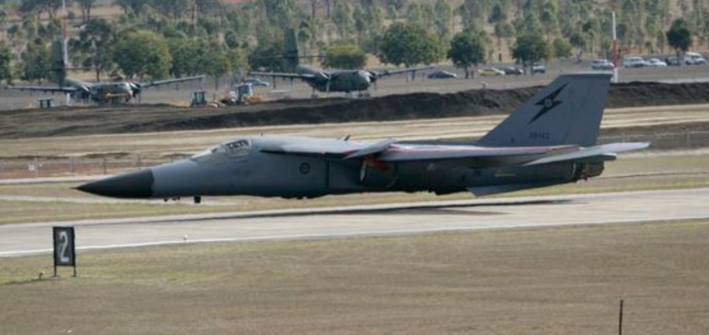
The F-111 crew sits side-by-side, both are enclosed in a capsule which separates from the aircraft in an emergency, a proven escape system which obviates the need for ejection seats. In addition to 17 F-111As for development work, 141 went to the 4881 Tactical Fighter Squadron at Nellis AFB in July 1967, for intensive trials evaluation. With four tandem triplets of bombs, the maximum speed proved to be about 925 km/h (575 mph) at typical attack height; with two bombs in the weapon bay and nothing exter¬nal it was Mach 1.1, roughly according with SOR 183. At height the attainable speed in the clean condition was about Mach 2. Ferry range with six 2271 litre (500 Imperial gallons) drop tanks is about 6400 km (3980 miles). These were powered by two 8392kg afterburning thrust Pratt & Whitney TF30-P-3 turbofans. In March 1968, six F-111As of the wing’s 428th Tactical Fighter Squadron under Colonel Ivan H. Dethman were rushed to Takhli, Thailand, to begin combat operations against North Vietnam. The first three aircraft launched on the first three missions vanished for ever, although the detachment later flew 55 missions successfully. The USAF discovered, as a prisoner of war from this deployment would later confirm, that a tailplane problem caused uncontrollable pitch-up and roll. A separate fatique problem caused wing spar cracks and, in 1969, resulted in the loss of an F-111A when its wing was torn off. In 1969, the entire fleet of 300 aircraft was grounded while an exhaustive structural review programme remedied these problems. GD delivered 141 of the A model with TF30 3 engines, including two YF 111A air¬craft rebuilt from a cancelled British order for 50 F 111K. The Strategic Air Command’s FB-111A, operating with two wings, is a very long-range variant powered by two 9230kg afterburning thrust Pratt & Whitney TF30-P-7 turbofans, with modified inlets, long-span wing, and provision for nuclear or thermonuclear weapons or up to 50 340kg HE bombs; 76 FB-111As were built. The Royal Australian Air Force bought 24 F 111C with long span wings and stronger landing gears, these suffering a nine year delay due to structural problems and contract uncertainties and were delivered to Australia in 1973 after lengthy delays. The F-111C differs from the F-111A model in having a longer-span wing and stronger landing gear. Four F-111Cs have been converted to the reconnaissance role and the remainder, like many USAF ‘Aardvarks’, are being equipped with Pave Tack pods for laser acquisition of ground targets.
One of six RAAF F-111C at Red Flag 07
The Royal Australian Air Force operates three versions of the F-111:
the F-111C strike fighter
the unique RF-111C, modified for photo-reconnaissance work, and
ex-US Air Force F-111G’s, which help ensure Australia maintains its strike capability until the F-111 is retired.
The F-111D, F-111E and F-111F are variants of what has become a highly specialised long-range strike aircraft ideal as a counter to the Soviet Sukhoi Su-24 and as a means of hitting targets in eastern Europe from the British Isles. These variants are located respectively at Cannon AFB, New Mexico, RAF Upper Heyford and RAF Lakenheath, England. Production amounted to 96 F-111D, 94 F-111Es and 106 F-111Fs. The F-111H was a proposed strategic bomber once perceived as an ideal interim step for the 1980s when it appeared that the Rockwell B-1 had been cancelled. The F-111K was the intended version for the UK’s Royal Air Force. Neither was built, and total production amounted to 562 airplanes.
The F 111D, of which 96 were built, has the slightly more powerful 8891 kg (19600 lb) TF30 9 engine and the totally different ‘Mk II’ avionics, with mainly solid state digital circuits. The F 111E (94) had only improved engine inlets, otherwise resembling an A. The final F 111F version (106) has the vastly improved TF30-100 engine, rated at 11385 kg (25100 lb) thrust, and a simpler and cheaper version of the F 111D avionics. In 1967 some $118 million was spent in the development of a multi sensor reconnaissance pallet which was test flown in the eleventh F 111A. There remained an intention to rebuild some or all D models as RF-111Ds. Since 1976 much further development has been in progress to update this vital and powerful tactical attack force. Grumman has been developing the EF 111A electronic warfare aircraft by transferring the ALQ 99 tac jamming system of the EA 6B Prowler to rebuilt F 111A airframes. In 1965 McNamara, before leaving the Pentagon, announced that 210 strategic bomber versions designated FB-111A would be bought to replace Strategic Air Command’s B 58 and older B 52 bombers. Increased costs caused the eventual force to be terminated at only 76, and these equip two small (30 aircraft) wings, styled Bomb Wing (Medium), the 380th at Plattsburgh and 509th at Pease. The FB 111A has a modest engine, the 9230 kg (20350 lb) TF30 7, a so called ‘Mk 2B’ avionics system, and the long span wing and strong landing gear. It can carry a theoretical bombload of 50 free fall bombs of nominal 340 kg (750 lb), actually weighing a total of 18710 kg (41250 lb). 76 FB-111As were completed in 1971. Using the fuselage and intakes of the F-111E, the FB-111A introduced the larger wings designed by Grumman for the US Navy’s F-111B, plus uprated engines.
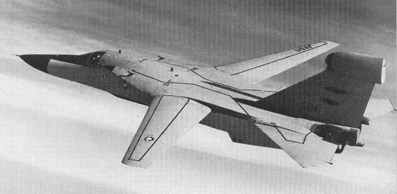
EF-111A
The EF 111A was born out of a series of studies undertaken during the late ’60s aimed at providing the USAF with a tactical EW system to replace its ageing fleet of EB 66 aircraft. The emergence of ALQ 99E tactical jamming system gave the green light for full scale airframe development and in January 1975, Grumman was awarded a $85.9 million contract for the construction of two prototype EF-111s. These aircraft were in fact preceded by an F 111A fitted with a ventral ‘canoe’ radome of the type proposed for the production models and which was used to test the aerodynamics of the installation together with five static air frames which were used in a series of electronic tests. The first fully aerodynamically representative prototype (AF serial 66 0049) made its maiden flight on 10th March, 1977 and was followed by a second aircraft (66 0041) which carried a complete electronic suite on 17 May 1977. Both aeroplanes were involved in an 84 flight company test programme and an 86 flight evaluation by the USAF. Surplus F 111A airframes were chosen for the programme and Grumman was assigned the task of converting the type into a dedicated EW platform.
In November 1979, full scale production of the EF 111A was sanctioned and the two prototypes were re worked to definitive standard. Aircraft number 049 reappeared on 19th June, 1981 and was initially retained by Grumman for further testing whilst 041 became the first ‘production’ air¬craft to be delivered to the USAF. Despite outward appearances, the EF-111A is a virtual re build of the original aircraft. During conversion, Grumman remove the wings and tail surfaces and strip the fuselage back to a basic keel structure. When the re build is complete, the original components have a fatigue life of approximately 8,000 hrs whilst the new features are rated for 10,000 hrs. The forward avionics bay remains unchanged and continues to carry the AN/APQ 160 navigation and the AN/APQ 110 terrain following radars which are standard to the F 111A. Aft of the radar boxes, a new oxygen converter has been installed along with a considerable quantity of new electronic equipment, the exact nature of which has not yet been cleared for publication. The basic geometry of the crew escape capsule is retained but the right hand side of the cockpit has been completely re built to house an electronic warfare officer (EWO) and his related controls. The pilot’s instrumentation remains essentially similar to that carried by the original aircraft but with some additions and re arrangement of individual items. The complete EF 111A cockpit layout is shown in the accompany¬ing illustration. Aft of the cockpit, the weapons bay has been extensively re worked to house the transmission and other elements of the Al Q 99. The installation takes the form of a pallet structure hung across the bay with nine transmitters attached to its underside and a range of related electronics above. What is known about the exact distribution of these items is shown in the accompanying inboard profile. Completing the weapons bay modifications is a 4.9m long canoe’ radome for the ALQ 99’s transmission antenna built into the underside of the bay doors. The electronics pallet is quoted as weighing 1,939kg with the ‘canoe’ adding a further 210kg, giving a total installation weight of 2,149kg. To provide power for the system, the original 60kVA engine mounted generators have been replaced with units rated at 90kVA. To cope with this increase, a new electrical sub system has been installed involving extensive re wiring. To cope with the heat output of the palletised ALQ 99, two new environmental control systems have been installed, namely the air cycling system from the F 111F and a refrigeration system to provide a constant 4.4 degrees C air flow for electronics cooling. The air cycling unit uses a ram air intake below the starboard main engine inlet duct and two exhausts mounted on either side of the rear of the under fuselage. The remaining modification of note concerns the vertical tail surface which has been re stressed to carry a fin top fairing and four side blisters designed to house a systems integrated receiver (SIR) group which is used to provide threat data for the various onboard EW systems. The fin top ‘pod’ is produced by Canadair and weighs, fully equipped, a respectable 432kg. An integral ‘glove’ is used to fair the installation into the vertical surface. The standard F 111A vent tank and HF antenna are retained within the fin structure. The EF-111A flew in production form on 28 June 1981. Production Ravens achieved an initial operational capability in November 1983 and entered service with a USAF unit in England in 1984. The 42nd and last was delivered in December 1985.
F-111A Engines: 2 x Pratt & Whitney TF30-P-3 turbofan 12.500/21,000 lb (5,670/9,525 kg). Wing span: 63 ft 0 in (19.20 m) fully forward, 31 ft 11.5 in (9.74 m) fully swept. Length: 73 ft 6 in (22.40 m). Height: 17 ft 1.5 in (5.22 m). Gross weight: approx 80,000 lb (36287 kg). Max speed: 1,650 mph (2,655 km/h) above 36,000 ft (11,000 m). Max range (internal fuel): 2,750 (4,425 km). Crew: 2.
EF-111A Engine: 2 x P&W TF30-P-3 turbofan, 18,500 lb thrust. Installed thrust: 164.6 kW. Wing span: 19.2-9.8 m (63-32 ft). Length: 23.16m. Height: 6.10m. Wing area: 48.8 sq.m Empty wt: 25,070 kg. MTOW: 40,340 kg. Max combat speed: 2,216 kph. Initial ROC: 5690 m / min. Service ceiling: 13,715 m. T/O run: 1350 m. Ldg run: 600 m. Fuel internal: 19,000 lt. Ferry range (on internal fuel): 3,706km. Unrefuelled endurance: 4 hr plus. Combat radius: 370-1,495km.
F-111B First fight: 18 May 1965. Wing span: 70 ft. Length: 67 ft 6 in
FB-111 Span: 72.5deg 10.34 m (33 ft 11 in); 16deg sweep 21.34 m (70 ft) Length: (with probe) 23.1 m (75 ft 9.5 in) Gross weight: (after in flight refuelling) 55747 kg (122900 lb) Maximum speed: (Sea level, clean, most versions) 1346 km/h (836 mph, Mach 1.1); (high altitude, clean) 2335 km/h (1450 mph, Mach 2.2)
FB-111A Engines: 2 x Pratt & Whitney TF30-P-7 turbofan, 20,350 lb / 9231 kg thrust. Wingspan: 70 ft 0 in / 21.34 m Wingspan swept: 33 ft 11 in / 10.34 m Length: 73 ft 6 in / 10.34 m Height: 17 ft 1.5 in / 5.22 m MTOW: 114,300 lb / 51,846 kg Speed: 1650 mph / 2655 kph Ceiling: 60,000 ft / 18,290 m Range: 2925+ mi / 4707+ km Armament: six SRAM missiles (or nuclear bombs) or up to 37,500 lb (17,010 kg) of conventional bombs. Crew: 2
F-111C Engine: Two Pratt and Whitney TF-30 turbofans (9,500 kg thrust each) 21.3m extended, 10.3m swept Sweep: 72.5-16deg Length: (with probe) 23.1 m (75 ft 9.5 in) Height: 5.3m Basic Weight: 24,000kg Gross weight: 51846 kg (114300 lb) Maximum speed: (Sea level, clean, most versions) 1346 km/h (836 mph, Mach 1.1); (high altitude, clean) 2335 km/h (1450 mph, Mach 2.2) Crew: 2
RF-111C Wing span: 19.2 m / 9.8 m (63-32 ft).
F-111D Span: 72.5deg sweep 9.74 m (31 ft 11.5 in); 16deg sweep 19.2 m (63 ft) Length: (with probe) 23.1 m (75 ft 9.5 in) Gross weight: 41958 kg (92500 lb) Maximum speed: (Sea level, clean, most versions) 1346 km/h (836 mph, Mach 1.1); (high altitude, clean) 2335 km/h (1450 mph, Mach 2.2)
F-111E Span: 72.5deg sweep 9.74 m (31 ft 11.5 in); 16deg sweep 19.2 m (63 ft) Length: (with probe) 23.1 m (75 ft 9.5 in) Gross weight: 41958 kg (92500 lb) Maximum speed: (Sea level, clean, most versions) 1346 km/h (836 mph, Mach 1.1); (high altitude, clean) 2335 km/h (1450 mph, Mach 2.2)
F-111F Span: 72.5deg sweep 9.74 m (31 ft 11.5 in); 16deg sweep 19.2 m (63 ft) Length: (with probe) 23.1 m (75 ft 9.5 in) Gross weight: 45360 kg (100000 lb) Maximum speed: (Sea level, clean, most versions) 1346 km/h (836 mph, Mach 1.1); (high altitude, clean) about Mach 2.5.
The F 16 was not originally planned as an equipment item for the inventory, but as a candidate for a Light Weight Fighter (LWF) technology demonstrator programme to examine the possibility of building a fighter significantly smaller and cheaper than the F 15. Five companies submitted proposals for an LWF on February 28, 1972, General Dynamics and Northrop were selected to build two prototypes each, designated YF 16 and YF-17, respectively, on April 13, 1972, and on January 13, 1975, the Secretary of the Air Force announced that the F 16 was the final choice. By this time, the emergence of a market, especially among a group of European NATO nations, had caused the programme rather quickly to be recast as an Air Combat Fighter (ACF), with procurement of an operational version promised by the USAF. At the same time, the original concept of a light and uncompromised close-combat dogfighter was changed to include all-weather capability in both the air to air and air to surface roles, with heavy loads of the full spectrum of tactical stores.
The first of two prototypes (72-01567) of the YF-16 (GD model 401) was airlifted from Fort Worth to Edwards AFB in January 1974 and was officially flown for the first time of the 2nd of February 1974, although this aircraft had made an unofficial and unscheduled flight on 20 January after becoming airborne in the hands of Philip Oestricher, who elected to take off when the tailplane was damaged during high-speed taxi tests. An ‘official’ first flight followed on February 2, and subsequent testing was encouraging. The chosen engine was a single Pratt & Whitney F100 PW 100 two shaft augmented turbofan, with maximum thrust rating of 10800 kg (23810 lb) with full afterburner. This engine was chosen because it was already fully developed and in production for the F 15. Although it has a modulated variable profile nozzle, it is fed from a simple fixed inlet and ventral duct to reduce complexity and cost. This reduces maximum high altitude Mach number to below 2.0, but this is considered of little consequence. Virtually all modern air combat takes place at medium to low altitudes at speeds in the order of 650 km/h (404 mph), and turn radius is far more important than speed. The F 16 pilot sits in a reclining McDonnell Douglas seat (of course, with zero/zero capability) and flies with a sidestick controller resembling a miniature control column on the right cockpit console. This small controller is easy to manage under conditions of high g acceleration, and the sloping seat also helps the pilot resist g forces. The controller hardly moves under the pilot’s input demands; instead it contains transducers which sense the pilot’s applied forces. The resulting electrical signals, and those from the rudder pedals, serve as primary inputs to a fly by wire (FBW) control system which also includes the digital autopilot, computer, weapon delivery system and power units driving the flight controls.
F-16E
The wing and fuselage are blended structurally and aerodynamically and, like the tail, incorporate major portions of graphite‑epoxy composite, glass‑fibre, titanium and other advanced materials. There are only five ribs in each wing, but no fewer than 12 spars, all linked to body frames. Long vortex extensions at the root give powerful lift at high angles of attack and allow the wing proper to be made significantly smaller. Along the top of the left extension strake is the M61 20‑mm (0.79‑in) cannon, with a 500‑round ammunition drum lying transversely in the top of the fuselage. About 3162 kg (6971 lb) of fuel is housed in various cells in the wing and fuselage which are governed as two tanks, with a flight‑refuelling receptacle in the top of the mid‑fuselage matched to the SAC Flying Boom type of refuelling method.
Moveable leading-and trailing-edge flaps, controlled automatically by the aircraft’s speed and attitude, enable the wing to assume an optimum configuration for lift under all conditions of flight. All flying controls are operated by a ‘fly-by-wire’ electronic system.
The F-16 has a single vertical tail surface, mid-set all-moving tailplane and mid-set wings of 40 degree leading-edge sweep.
The tailplane is of the taileron type, the two halves operating in unison for pitch control and differentially for roll control.
The full-span ailerons are of the flaperon type, again operating differentially for roll control and in unison for increased lift.
The leading edges are hinged to allow the automatic flight-control system to schedule them as automatic leading-edge flaps and, in concert with the ‘flaperons’, provide a measure of variable camber to the wing.
Take-off and landing has the leading edge flaps at 2 degrees and the flaperons down 20 degrees.
Initial climb has the leading-edge flaps angled down at 15 degrees and the flaperons down at 20 degrees.
High speed flight has the leading-edge flaps and the flaperons both at 2 degrees up.
For manoeuvring, the leading-edge flaps are angled down at 25 degrees and the flaperons level.
Approach has the leading-edge flaps at 15 degrees and the flaperons down at 20 degrees.
In the nose is a Westinghouse X‑band pulse‑doppler radar, with planar‑array aerial. It can function in many modes including air-to‑air look‑up or look‑down, auto‑acquisition dogfight, air‑to‑ground ranging, ground mapping, expanded mapping, doppler beam-sharpening, beacon, ‘freeze’ (fixed display), and two types of Sea Mode for anti-shipping missions. Delco make the computer, Marconi‑Elliott of Britain, the advanced HUD (head‑up display), Kaiser the head‑down display (HDD) and Singer‑Kearfott the inertial navigation system. Up to 6894 kg (15 200 lb) of weapons, ECM pods and tanks can be carried on nine pylons.
The YF-16 prototypes were being flown by six pilots, two each from General Dynamics, the Air Force Flight Test Centre and the Tactical Air Command. The single-seat, single-engine aircraft, 47 feet long with a 30-foot wingspan, is designed as a compact, low-cost fighter for air-to-air combat. It also can carry nearly 9,0001b of missiles and bombs for air-to-ground missions. The YF-16 is powered by a Pratt & Whitney F-100-PW-200 turbofan, the same engine used in the Air Force F-15 fighter. The F-100 engine produces about 25,0001b / 10814kg of thrust with full afterburner.
The F-16 is built in three major subsections. Some 80 percent of the airframe is made of conventional aluminium alloy, and about 60 percent is from sheet metal. Steel, composites and titanium represent about 8 percent of the structure. The wing is a cropped delta with a 40-degree leading-edge sweep. It has a 4 percent thickness/chord ratio and a 64A204 airfoil section. The structure consists of eleven spars and five ribs. Upper and lower skins are machined from a single piece. The wing is blended into the fuselage which creates a significant stowage area for internal fuel, which accounts for 31 percent of the loaded weight of the F-16. Leading edges are blended into the fuselage with strakes which, at high angles of attack, create vortices that maintain energy in the airflow over the wings, delaying root stalling and contributing to directional stability. Trailing edges have inboard “flappers” which combine the functions of flaps and ailerons. They can be drooped to 20 degrees. Leading-edge flaps contribute to the aircraft’s legendary manoeuvrability. The single vertical tail is of multi-rib, multi-spar construction in aluminium, with the skin made of graphite epoxy. Two ventral fins are made of glass fibre. There is an all-flying tailplane. Main and nosewheel gear retract into the fuselage. The single air intake is mounted underneath the fuselage, giving the F-16 its distinctive profile. This location was chosen to provide minimal airflow disturbance over a wide range of aircraft attitudes. Location of the nosewheel gear aft of the intake means that FOD (foreign object damage) ingestion problems have been minor. The intake is of fixed geometry. A separation strut provides additional tunnel ridigity. Many parts are interchangeable between port and starboard including the horizontal tail surfaces, flaperons and most of the main landing gear. The view from the cockpit is exemplary. A polycarbonate clamshell canopy encloses the pilot who sits on an ACES II rocket powered ejection seat, cleared for ‘zero-zero’ performance up to 600 knots and/or 50,000 ft. The inside of the canopy is tinted with a thin gold film, which dissipates radar energy. The seat is raked backwards at 30 degrees, to enhance the pilot’s ability to withstand high g. Instead of a conventional control column, the F16 is fitted with a sidestick controller mounted to starboard. “Fly-by-wire” powered controls and artificial “feel” require the sidestick to be moved only millimetres.
In April 1975, the first definitive USAF contract specified six F‑16As and two tandem‑seat dual‑control F‑16B trainers with full combat capability (the B has 17% less internal fuel). The USAF said it would buy 650 aircraft in all, but this total was subsequently been increased to a currently planned force of 1388 aircraft. On June 7, 1975, at the Paris air show, it was jointly announced by Belgium, Denmark, the Netherlands and Norway that they had selected the F‑16 over two other candidate aircraft to replace the F‑104, buying initial totals of: Belgium 90A+ 12B+ 14 options; Denmark 40A+8B+ 10 options; the Netherlands 84 (A, B combined)+ 18 options; and Norway 60A+ 12B (no options).
In September 1976, Iran ordered 160 from the US Government, signifying its eventual requirement for a total of 300. Iran is unlikely to participate in manufacture, but the four European countries signed a complex collaborative/offset deal which gives them the right to make major parts of the airframe, engine and equipment, both for their own purchases and those of other customers including the USAF. Since 1976, Turkey has expressed a wish to join this consortium, but no decision had been announced by them by early 1978.
F-16XL
The first production F 16A (75 0745) flew on 8 December 1976 at Fort Worth, Texas, and the first F 16B on August 8, 1977. The first operational F-16A was delivered in January 1979 to the 388th Tactical Fighter Wing at Hill Air Force Base, Utah and its first overseas unit, the 8th TFW at Kunsan AB, South Korea, on 1 November 1980. The first USAF unit in Europe to re-equip with Fighting Falcons was the 50th TFW at Hahn AB, West Germany on 1 December 1981. As part of a major policy decision to upgrade the equipment operated by second-line units, the F-16 has already reached the South Carolina Air National Guard, deliveries beginning in mid-1983, followed by other ANG units, as the aircraft were replaced in USAF by later models. Initial USAF production versions were the F-16A single-seater and F-16B two-seat operational trainer with an extended canopy and dual controls, powered by Pratt & Whitney F100 engines and equipped with APG-66 radars. Four European countries selected the F-16A/B, with manufacture by a consortium with two final assembly lines, in Belgium and The Netherlands.
First F-16 assembled in Europe – Belgium Air Force F-16B FB-01 first flying December 1978
The European F-16A/B aircraft have been upgraded under the Mid-Life Update program and designated F-16AM/BM.
The F-16C and F-16D aircraft, which are the single- and two-place counterparts to the F-16A/B, incorporate modern cockpit control and display technology. The F-16C/D models were the result of a multi¬national staged improvement programme (MSIP) initiated in 1980. Changes include the introduction of a more capable APG-68 radar with increased detection range and track-while-scan mode, plus new cockpit displays with multifunction CRTs and a wide-angle headup display and an increase in the maximum take-off gross weight. First flown in December 1982, the F-16C/D became the standard production model, although the earlier F-16A/B was still available for export. Following General Elec-tric’s success in the Alternate Fighter Engine competition, F-16C/Ds delivered from FY1985 have comprised mixed batches of General Elec¬tric F110 and Pratt & Whitney F100-220 powered aircraft. Engine contracts are to be agreed annually, with the lowest bidder supplying the majority of the power plants for that year. In FY1985 General Electric provided 75 per cent of the engines needed for F-16C/D production. Export aircraft are available with either engine. The TUSAS organisation in Turkey is to build F-16C/D aircraft and F110 engines for the Turkish Air Force, which is purchasing 160 aircraft, including an initial batch supplied by General Dynamics. Deliveries of TUSAS assembled F-16s is scheduled to begin in 1988. The F-16CJ is a modified F-16C for the SEAD role. By June 1987 2,975 F-16s of all versions had been ordered, including aircraft for licence production (Turkey – 278, South Korea – 108, Belgium – 222, Netherlands – 300), and 1,774 had been delivered. Early in 1987 Bahrain became the 16th nation to order the F-l6, contracting for 12 aircraft powered by General Electric F110 engines. The Block 60 F-16E single and F-16F two-seat fighters feature technology improving the combat effectiveness and multi-role capability of the aircraft. Deliveries of these variants started to the United Arab Emirates as the first customer. The first Block 60 made its maiden flight in December 2003. Israel took delivery of the F-16I, which is a customized version of the F-16E/F with Israeli avionics and weapons. The F-16R is a reconnaissance version with an underfuselage pod, and the F-16N is an ‘Aggressor’ version for the US Navy. General Dynamics has elected to improve the overall performance of the F 16 in the ground attack role by installing a new cranked arrow wing. With 120 per cent more wing area and two fuselage plugs lengthening the fuselage 54 ft 1.86 in (16.51 m) to accommodate the longer root chord, the double delta F 16XL carries 82 per cent more internal fuel. Stores are carried tangentially to the wing undersurface on 17 hardpoints, and drag fully loaded is some 60 per cent less than with conventional carriage. Radar cross section is also halved. The reduction in drag and the greater fuel capacity has a dramatic effect on the F 16XL’s payload/range performance, enabling the aircraft to carry twice the payload of an F 16A to a 45 per cent greater combat radius. Penetration speeds are increased by up to 100kt to around Mach 0. 9. Air to air performance is also improved, with the 9g manoeuvre envelope doubling in size. Manoeuvre capability fully loaded is also improved from 5.5g to 7.33g. Instantaneous turn rate is increased. The variant first flew on 3 July 1982. The Air Force’s evaluation involved four F 15s and two F 16XLs. Boeing, Rockwell and McDonnell Douglas co operated with NASA to set up a series of supersonic laminar flow tests involving a single seat F 16XL in flights beginning in 1991. When these showed promise, a two seat XL was used for the second series of fights during which more than 40 flights were completed by late 1996. Research results indicate it is possible to make a 4% weight saving by applying a laminar flow wing to supersonic airliners. Of the two F 16XLs built by GD as a private venture, one is a single seater powered by a Pratt & Whitney F100 and the other is a two seater powered by the General Electric F110.
The F-16XL has a 56in / 1.42m longer fuselage boosting fuel capacity by 80%. The F-16XL has a maximum of 29 hardpoints available on 17 stores stations. The stores stations are semi-conformal to minimise drag, which is 58% less than that of the F-16, enabling the F-16XL to carry twice the payload 45% further than the basic F-16.
During the 1970s and early 1980s considerable research was undertaken into a host of aeronautical fields but this was generally performed with conversions of existing aircraft such as the F-16 Fighting Falcon converted by General Dynamics into the F-16/AFTI for investigation of direct-force controls within the overall context of the CCV (Control-Configured Vehicle) portion of the Advanced Fighter Technology Integration programme, which was intended to create a quantum leap in fighter manoeuvrability.
The very first YF-16 (72-1567) was rebuilt in December 1975 to become the USAF Flight Dynamics Laboratory’s Control-Configured Vehicle (CCV). Fly-by-wire flight controls and relaxed static stability found on all Vipers made the YF-16 an ideal candidate to evaluate control of an aircraft beyond conventional means, with independent or ‘decoupled’ flight surfaces. The YF-16/CCV could rise or fall using direct lift, move laterally by direct side force, or yaw, pitch, or roll regardless of the direction of flight. Twin vertical canards beneath the air intake and flight controls permitted use of wing trailing edge flaperons in combination with the all-moving stabilator. The YF-16/CCV flew on 16 March 1976, piloted by David J. Thigpen. On 24 June 1976, the ship was seriously damaged in a landing after its engine failed on approach. The flight test programme was resumed and lasted until 31 July 1977, when 87 sorties and 125 air hours had been logged.
Early in the development stage, General Dynamics wanted to market a simpler version of the F-16 for export, and teamed up with General Electric to create a version powered by the 8165kg thrust General Electric J79-GE-17X single-shaft turbojet, a development of the engine employed on the F-104 Starfighter and F-4 Phantom. As the J79-GE-119, this engine was installed on a full-scale development F-16B (75-0752) bailed back from the USAF. The Turbojet required a lower airflow than the P&W FI00-PW-200 used on all production F-16A/Bs so the shape of the air intake was altered. Since the J79 engine was 18 in (46 cm) longer than the F100, the rear fuselage was extended aft of the stabilator pivot point by that amount. The resulting F-16/79, made its first flight on 29 October 1980, and was existant in F-16/79A (single-seat) and F-16/79B (two-seat) versions.
The F-16/101 was a similarly re-engined example powered by a General Electric YJ101 two-shaft augmented turbojet engine delivering about 15,000 lb (6803 kg) thrust, had performed well on the Northrop YF- 17 and its builder wanted to demonstrate the much improved DFE (derivative fighter engine) version, capable of up to 26,500-lb (12,020-kg) thrust on a single-engine F-16. The retrofit was made on this first full scale development F-16A (75-0745) which flew with the GE engine on 19 December 1980. The F-16/101 made 58 test flights and logged 75 air hours before the programme ended in July 1981. The F-16/101 was not adopted but the way had been paved for development of an improved GE engine, the F 110, on the Fighting Falcon beginning with F-16C block 30/32 aircraft.
In June, 1975, four European countries (Belgium, Netherlands, Derunark, and Norway) announced plans to purchase 348 fighters. In February 1978, the first European F-16 assembly line opened at Sabca/Sonaca where Belgium took delivery on 29 January 1979 of the first locally-manufactured F-16 out of the country’s original order for 116 aircraft (96 F-16As and 20 F-16Bs). Belgian F-16As were serialed FA-01/136 (78-116/161; 80-3538/3546; 80-3547/3587; 86-0073/0077; 87-0046/0056; 88-0038/0047; 89-000110011; 90-0025/0027). F-16Bs were serialed FB-01/24 (78-0162/0173; 80-3588/3595; 87-0001; 88-0048/0049; 89-0012). FA-01/55 and FB-01/12 were upgraded to F-16A/B block 10 standard, while FA-56/136 and FB-25/24 were built as F-16A block 1s (big tail) aircraft.
Norway acquired seventy-two F-16A and B model Lawn Darts (sixty F-16As and twelve F-16Bs) from the Netherlands’ Fokker production line between 15 January 1980 and 4 June 1984. Six F-16A/B block 15 (four F-16A and two F-16B) attrition replacements were later ordered. Norway employs the F-16 in a defensive role, Scandinavian geography dictating an important anti-shipping mission. On 12 December 1979, the first Fighting Falcon for the RNAF completed its maiden flight from Fokker’s Schipol plant. Norwegian aircraft have drag chutes to operate on snowy and an identification spotlight for use during long dark winters.
In April 1978, the second European F-16 assembly line (after Belgium) opened at Fokker-VFW in the Netherlands. In May 1979, the first Dutch-assembled F-16 made its maiden flight. Holland later increased its F-16 purchase from 102 to 213 aircraft.
The USAF continues large-scale procure¬ment of F-16s, with the 180 approved in FY1986 taking total purchases to 1,859. In October 1986 the F-16 won the Air Defence Fighter (ADF) competition, a modified version of the F-16A being selected instead of the Northrop F-20A Tigershark. The ADF contract will cover the modification of existing F-l6As, and will not be for new-build aircraft. In April 1987 the US Navy took delivery of the first F-16N supersonic adversary aircraft of the 26 ordered. By 1994, production of the F-16 had been taken over by Lockheed Martin.
The F-16 Block 70 variant, also known as the F-16V, features cutting-edge enhancements including the AN/APG-83 AESA radar, new mission computers, a digital cockpit, and advanced electronic warfare systems. These upgrades provide superior situational awareness, survivability, and multirole performance.
On 18 March 2005, Lockheed Martin Aero plant in Fort Worth, Texas, delivered the final F-16 Fighting Falcon for the US Air Force; F-16CJ 01-7053. Lockheed Martin continues to produce the F-16 fighter for international customers. A total of 2231 F-16s have been produced for the U.S. Air Force.
F-16A Engine: P&W F100-220, Normal-12,420 lb st, military-14,670 lb st, afterburn-23,830 lb st. Length: 47.638 ft / 14.52 m Height: 16.699 ft / 5.09 m Wingspan: 31.004 ft / 9.45 m Wing area: 300 sq ft (27,9 sq.m). Max take off weight : 35390.3 lb / 16050.0 kg Empty wt: 15,137 lb (6 865 kg). Internal fuel: 6,972 lb (3 162 kg). Max. weight carried : 19800.9 lb / 8980.0 kg Air superiority gross weight: 23,357 lb (10952 kg) with ammunition and two Sidewinders. Wing loading: 78 lb/sq ft (397 kg/ sq.m). Thrust/weight ratio: 1.02. Max. speed : 1158 kts / 2145 km/h Cruising speed : 533 kts / 988 km/h Initial climb rate : 41338.58 ft/min / 210.0 m/s Service ceiling : 50000 ft / 15240 m Range : 1042 nm / 1930 km Fuel fraction: 30%. Armament : 1x MK 20mm M61A1, 5440kg ext 9pt. / 2-6 AIM-9 Sidewinder Seats: 1.
F 16B Engine: P&W F100-220, Normal-12,420 lb st, military-14,670 lb st, afterburn-23,830 lb st. Wingspan: 10m. Length: 15.03m. Height: 5.09m. Wing area: 27.9sq.m. Empty wt: 7909 kg. Internal fuel: 2745 kg. MTOW: 16,057 kg. Seats: 2
F-16C Engine: General Elec¬tric F110 Seats: 1
F-16C Engine: Pratt & Whitney F100-200 turbofan, 23,840 lb Wingspan: 31 ft / 9.45 m Length: 49 ft 6 in / 15.09 m MTOW: 35,400 lb / 16,057 kg Max speed: 1350 mph / 2173 kph Max ferry range: 2415 sm / 3890 km Armament: 1 x 20 mm cannon (515 rds) External load: up to 20,450 lb / 9276 kg
F-16C Fighting Falcon Engine: 1 x Pratt & Whitney F100-220 or General Electric F110-GE-100 Installed thrust (dry – reheat): 67 – 113 kN. / 27,600 – 23,450 lb / 12,519 – 10,637 kg Span: 10 m / 32 ft 9.75 in Length: 15.1 m / 49 ft 4 in Wing area: 27.87 sq.m / 300.0 sq.ft Height: 16 ft 8.5 in / 4.09 m Empty wt: 8315 kg / 18,335 lb MTOW: 19,187 kg / 42,300 lb Warload: 5413 kg. Max speed: 1320+ mph / 2124+ kph / M2+ at 40,000ft/12,190m Initial ROC: 50,000+ fpm / 15,240+ m/s Ceiling: 18,000+ m. TO run: 760 m. Ldg run: 760 m. Combat radius: 925+ km / 575+ mi Fuel internal: 4060 lt. Air refuel: Yes. Armament: 1 x 20 mm, 2/4/6 x AAM Hard points: 5 + 2 wing tips. Disposable stores: 20,450 lb / 9276 kg Seats: 1.
F-16CJ Engine: Pratt & Whitney F100, or General Elec¬tric F110 or Pratt & Whitney F100-220 Seats: 1
F-16D Engine: Pratt & Whitney F100, or General Elec¬tric F110 or Pratt & Whitney F100-220 Seats: 2
F-16E Engine: 1 x General Electric F110, 7700/13150kg Max take-off weight: 21770 kg / 47995 lb Wingspan: 10.4 m / 34 ft 1 in Length: 16.5 m / 54 ft 2 in Wing area: 62 sq.m / 667.36 sq ft Max. speed: 2200 km/h / 1367 mph Crew: 1
F 16XL Engine: General Electric F110 Length: 54 ft 1.86 in (16.51 m) Hardpoints: 17 Penetration speed: Mach 0. 9. Manoeuvre capability: 7.33g. Seats: 2
F 16XL Engine: Pratt & Whitney F100 Length: 54 ft 1.86 in (16.51 m) Hardpoints: 17 Penetration speed: Mach 0. 9. Manoeuvre capability: 7.33g. Seat: 1
F-16/79 Engine: General Electric J79-GE-119
F-16/101 Engine: General Electric YJ101, 26,500-lb (12,020-kg)
Engine: 1 x P+W F-100-PW-100, 112.1kN Max take-off weight: 9780-15000 kg / 21561 – 33070 lb Empty weight: 6330 kg / 13955 lb Wingspan: 9.3 m / 30 ft 6 in Length: 14.4 m / 47 ft 3 in Height: 5.0 m / 16 ft 5 in Wing area: 26.0 sq.m / 279.86 sq ft Max. speed: M1.2 Ceiling: 19000 m / 62350 ft Range w/max.fuel: 3200 km / 1988 miles Range w/max.payload: 500 km / 311 miles Armament: 1 x 20mm machine-guns, 5000kg of bombs or missiles Crew: 1
Engine: one 129 kN (26,000 lb st) General Electric F110-GE-129 or Pratt & Whitney F100-P-229 turbofan Length 15.03m (49 ft 4 in) Height 5.09m (16 ft 8.5 in) Wing span (over tip launchers) 9.45m (31ft 0 in) Take-off weight (clean): 9.791 kg (21,585 lb) Max Take-Off Weight: 19.187 kg (42,300 lb) Armament: one 20mm M61A1 Vulcan six-barrel gun 515 rounds; 9276 kg (20,450 lb) of disposable stores Hardpoints: nine