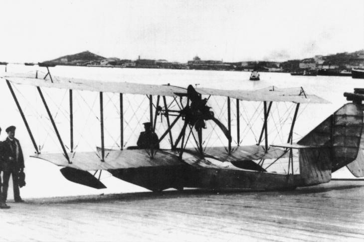
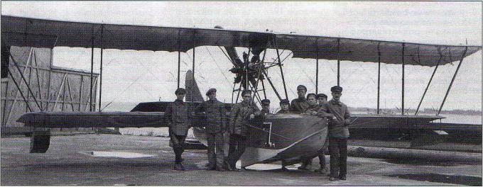
The M-15 type (Russian: Григорович М-15) was a development of the excellent M-9 and was characterized by the introduction of a new power plant with greater power with a certain reduction in the general dimensions, especially in the wing area. This model was built at the S. S. Schetinin PRTV facilities and is therefore alternatively known as the Schetinin M-15 or Sch M-15.
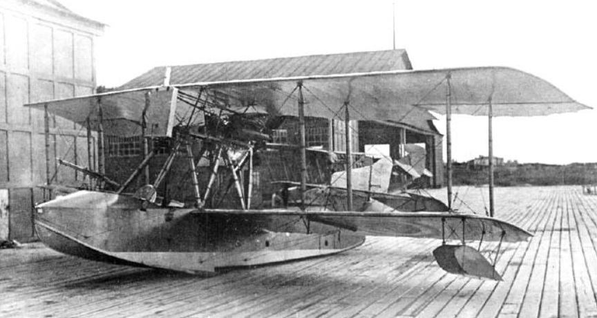
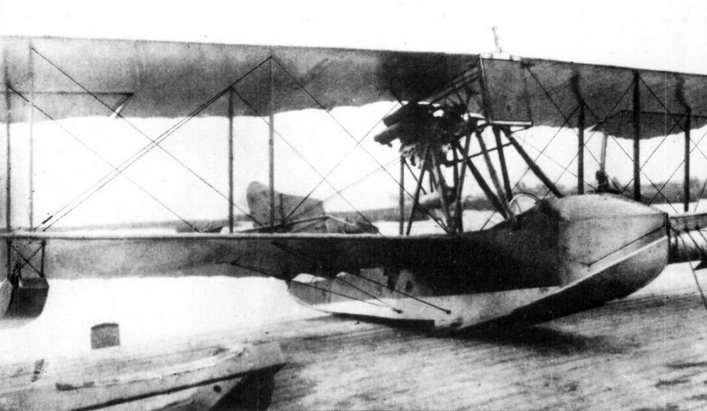
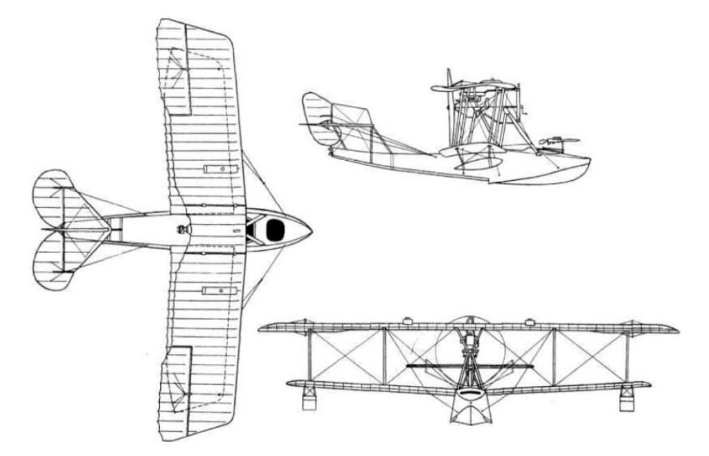
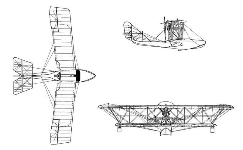
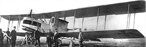
The M-15 was designed as a two-seater biplane flying boat with an unequal wingspan, made of wood and powered by a 150 hp Hispano-Suiza linear motor moving an “Integral” propeller with a diameter of 2.55 m.
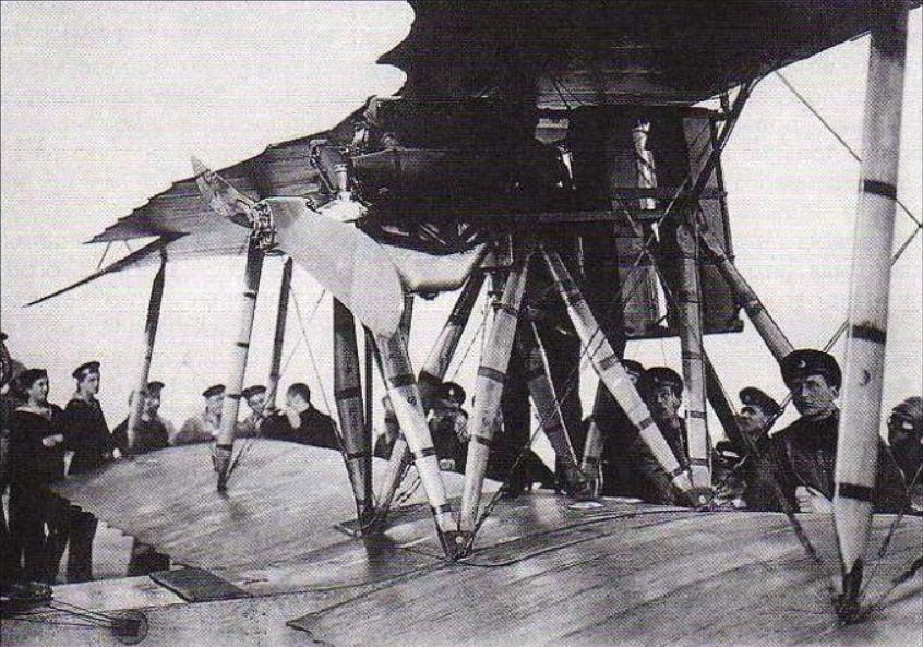
In general, it repeated the construction characteristics of the M-9, but the wing box had only two sections and a reduced wing surface in both planes. The hull was of a completely new design and the remarkable engine was mounted on a complex system consisting of 10 bracing spars.
The M-15 crew consisted of a pilot and a gunner/mechanic. Both crew members were located in a common cabin, sitting side by side. The crewman on the right operated a Maxim or Lewis machine gun located in a position forward that was accessed by crawling from the cockpit.
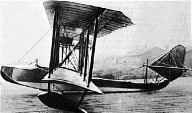
The prototype with factory number 1079 was found ready for November 6, 1916 and that same day it was presented to the naval authorities. After a few short test flights in which the model reached a height of 500 m in just 4.5 minutes (with a load of 350 kg) it was accepted for service with the Fleet. Subsequently, it was decided to send the prototype to the Baku Naval Flight School, where test days were to be carried out under operating conditions in December.
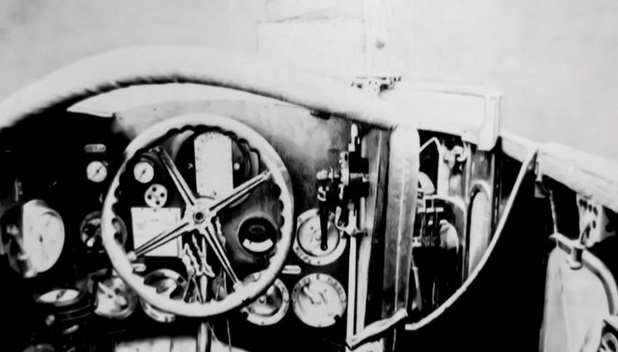
In January 1917 requests for modification of the flying boat M-15 were received from Baku, but most were aimed at a more comfortable arrangement of instruments and improvements in control, as well as claims about the quality of finish.
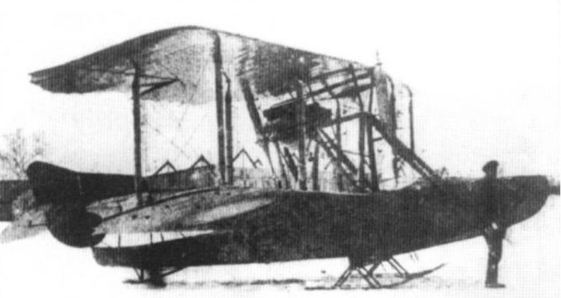
One of the first requests to modify the model was received by PRTV on January 21, 1917, when the observation officer G. Ya. Erdeli urgently requested, on the instructions of his superiors, skis according to the drawings presented by the pilot Alexandr Prokofiev-Severski.
Soon a flying boat was modified in this configuration and on February 9, with its designer at the controls, it made a test flight. The pilot reported that the was trimmed, took off smoothly, reached a height of 1,000 m in 7 minutes, and landed on the ice without difficulty.
The consequent speed tests showed that the new undercarriage only slightly reduced performance and, however, significantly increased the model’s operating capabilities.
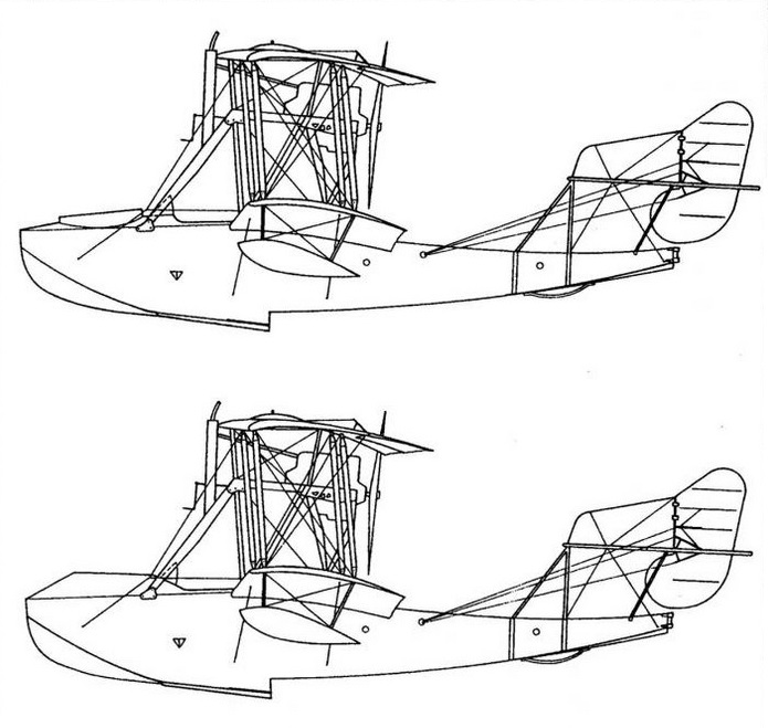
From the aeronautical point of view, the M-15 was positively valued. This model featured more speed and climb than the M-9. Its excellent response to controls was highlighted. During the process a firing point was installed in the bow of the model to install a Maxim or Lewis machine gun in two possible variants of nose configuration.
In operation, the M-15 was defined as an intermediate version between hunting and reconnaissance flying boats and in combat conditions it was superior to the M-9, so it was decided to approve its serial production.
The excellent results obtained during the tests of the M-15 motivated the request to build 80 copies in a first contract signed on November 24, 1916.
Contract date: November 24, 1916 Number of copies: 80 + 20 Serial numbers: 1101-1153 18,000 rubles for each copy with a Hispano-Suiza engine of 150 hp and 17,500 rubles for spare copies without a motor. Delivery scheduled for April 15, 1917. Partially completed. Copies 1154-1163 were not delivered due to the absence of engines. The contract was modified on April 17 to 60 copies and 15 spare parts.
Contract date: January 30, 1917 Number of copies: 1 Serial numbers: 1079 Contract for the purchase of the prototype.
Production of the M-15 began in the second half of 1916 and continued until the end of 1917. Unfortunately, the supply of Hispano engines was quite limited, so the M-15 failed to displace the M-9 in its flying boat role.
This problem with the supply of engines represented a severe blow to Russian aeronautical development, since most of the designs from the end of 1916 and the beginning of 1917 were based on Hispano-Suiza power plants with powers between 140 and 200 hp, who had been contracted in France and could not arrive on time.
The number of copies produced reached 54 units, including the prototype, of which almost more than half was used in the Baltic.
More than 30 units were delivered to the Baltic Fleet, about 20 units were redirected to the Black Sea and two units were delivered to the Baku flight school (prototype 1079 and 1144). The military designation of the model was SchI (Schetinin with Hispanic). Generally the model was used in reconnaissance missions.
The Red Air Fleet used several of these examples. From the summer of 1917 the units produced were used primarily as trainers.
Two copies of the M-15 went to Finland during the events of 1918, being framed in the local air force with the registration numbers C68/18 and C69/18. These specimens had been abandoned after the evacuation at the Åland and Turku bases, on the Baltic islands. In one of them, the Russian pilot J. Herbert would fly from Åland to the Finnish mainland and would be appointed an officer in the Finnish air force. This example remained in service in Finland until 1919.
The Germans captured some specimens that were displayed as war trophies. There is no evidence that they were ever used in service.
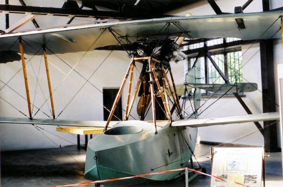
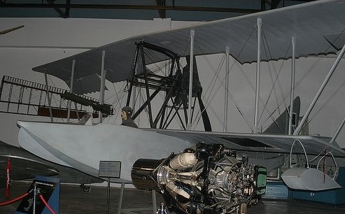
A perfectly preserved example is kept at the Polish Aviation Museum (Polish: Muzeum Lotnictwa Polskiego w Krakowie) located in Kraków, Poland. This flying boat, originally registered SchI-1, was damaged as a result of a bad landing on September 29, 1917, when the Russians left the Arensburg base on Ezel Island.
The Germans captured the flying boat and took it to Berlin as a war trophy. It was kept on static display in a Berlin Aviation Museum until 1945, when it was transferred to Poland.
М-15 Engine: Hispano-Suiza, 150 hp Upper wingspan: 11.50 m Wing area: 45.48 m² Length: 8.43 m Height: m 3.10 Empty weight: 840 kg Flight weight: 1320 kg Fuel and oil weight: 184 kg Maximum load: 480 kg Payload capacity: 350 kg Wing loading: 29.5 kg/m² Power load: 9.45 kg/hp Speed at sea level: 125-130 km/h Cruising speed: 106 km/h ROC: 91 m/min Ceiling: 3500 m Endurance: 5.5 hours Time to 1000m: 8.5 min Time to 2000m: 20min Armament: One 7.62mm machine gun Bombload: 65 – 100 kg Accommodation: 2
Grigorovich M-5 (alternative designation Shch M-5, sometimes also Shchetinin M-5 (Russian: Григорович М-5)) was a successful Russian World War I-era two-bay unequal-span biplane flying boat with a single step hull, designed by Grigorovich. It was the first mass production flying boat built in Russia.
During the summer and autumn of 1914 several flights were made on the M-2, proving that it still needed to work on the design in order to achieve a model capable of satisfying the needs of the Russian naval forces. The improvements introduced in the M-3 model did not bring the expected success either and this was understandable considering that the M-3 was just a version of the previous model with a more powerful engine and a new wing profile. The tests of this model did not show great differences in relation to the base model. Also unsuccessful was the later model M-4, a version with slight improvements to the hull design, new changes to the airfoil, and the same engine as the M-3.
It was produced, primarily to replace foreign built aircraft, including Curtiss Model K and FBA flying boats.
In his design Grigorovich used the information obtained from the French FBA models, which operated with the Baltic Fleet. On the way to obtaining the best possible design for the new model, Grigorovich decided to go to the Petrograd Polytechnic Institute, where one of the best aerodynamics laboratories in all of Europe existed, with a wind tunnel run by VA Sliesariev.
The M-5 was of a wooden construction, the hull was covered in plywood and the wings and tailplane were covered in fabric. Aft of the step the hull tapered sharply into little more than a boom, supporting a characteristic single fin and rudder tail unit, which was braced by means of struts and wires. It was normally powered by a 100 hp Gnome Monosoupape engine mounted as a pusher between the wings, but some used 110 hp Le Rhône or 130 hp Clerget engines. The pilot and the observer were accommodated side-by-side in a large cockpit forward of the wings, the observer provided with a single 7.62 mm Vickers machine gun on a pivoted mounting.
The M-5 was a development of the previous models with better hull hydrodynamics and modifications to the tail section for greater efficiency. Unlike earlier models, the wings were inserted into the sides of a deeper hull. The wingspan and surface of the lower plane were increased.
Grigorovich devoted great attention to strengthening the hull structure, especially in the areas that were in direct contact with the water. The railing was modified with a decrease in its height in the center to 70 mm and towards the sides of 140 mm. The sides of the bottom had some slats that allowed the flying boat to stay on the launching surface when leaving the water.
The structure was made of ash covered with 3 mm plywood on the edges and 5 – 6 mm on the bottom. 10 mm plywood was used in the recess area. The internal structure was made up of frames with diagonal reinforcement supports.
The assembly of the hull was done with brass screws with a lead or zinc coating. The joints in the hull skin were reinforced by plywood plates fixed with copper rivets from the inside. In the lower outer area of the hull, the joints were covered with 0.3 mm copper sheets and soldered together with tin. On the outside the wood coating was covered with varnish and on the inside with pitch. A special “marine” glue was also used during the assembly of the different pieces. It is interesting to note that all the work was manual. The hull had good rigidity, but even so breakages were common in aviation schools by inexperienced students.
The construction of the wings, the stabilizer and the keel of the vertical empennage was made of pine wood. The elevators and rudders were built from a light structure of thin-walled steel tubes (30×28 and 20×18 mm) with some wooden ribs and fabric covering.
The wing featured a double spar structure, built from I-profile pine pieces with holes to save weight. The wing ribs were made from 20 x 5 x 5 mm pieces of plywood, also lightened by perforations. Its wing profile was extremely thin (4% chord bristle). The interplanar supports were made of wood and the cross tensors were made of 5-8 mm cables. Cables were also laid between the wing box and the nose of the flying boat. The cables for the control surfaces were located on the outside of the flying boat, making them easy to service and repair.
The horizontal plane of the tail was raised to distance it from the effect of the water by means of a pyramidal structure of steel tubes and tension cables. This structure failed to ensure good rigidity and as a result the M-5’s tail twisted appreciably during turns and constantly vibrated. Despite this, an accident due to breakage of the tail unit was never recorded. The stabilizer was fixed to the tail bar and could be adjusted on the ground to change the angle of incidence. The bottom ski-paddle tested on the M-4 was eventually removed.
Most of the M-5s used the 100 hp Gnôme Monosoupape, which was installed in a steel tube structure fixed to the central supports of the wing box. This engine drove a 2.60 meter Shauviere propeller. Grigorovich constantly tried to improve the characteristics of the M-5 by using more powerful power plants (the 110-120 hp Le Rhône and the Clerguet were tested) of 130 hp, but when using these engines the performance worsened instead of improving, because as the weight increased, stability worsened and control became more difficult.
The manual ignition crank was located in the front region of the engine. The main fuel tank was located in the hull, behind the cockpit. The M-5 eliminated the tank from the upper plane. To get the fuel to the engine, a manual pump was used, which generated pressure in the tank, causing the fuel to rise constantly. The oil tank was originally located at the junction of the upper half-planes, but was soon enlarged to be located a little lower, at the junction of the central supports.
Pilot and observer were accommodated side by side in an open cabin, located immediately in front of the planes; In a few examples, the observer, located on the right, was in charge of handling a single machine gun mounted on a mobile mount. Additionally, the M-5 could carry an assortment of 8 kg bombs or two 50 kg bombs, directly in the cabin in the case of the small ones and hung in the case of the larger ones.
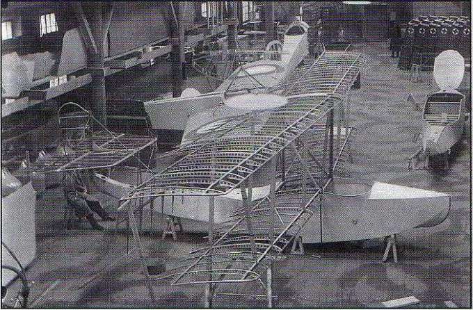
Assembly of M-5 at the Schetinin Factory
The first prototype M-5 was built at the Schetinin Factory in April 1915 and in May Ya. I. Siedov-Sierov carried out the tests on Kestovski Island. As early as April 16, S. S. Schetinin informed the Naval General Staff (MGSh) about the readiness of the factory to build four M-5 specimens at a cost of 9,500 rubles per unit, with deliveries from May 10 to 5 June. This proposal was accompanied by the promise to send, if necessary, all these planes and the assembly brigade made up of engineer, pilot and mechanic to Sevastopol to carry out the tests in which it was expected to reach a climb of 500 meters in 10 minutes. with a payload of 310 kg.
One of the first M-5s factory number 331 during the tests at the PRTV experimental station in July 1915.
In response to this proposal, a group of naval pilots visited the factory and on April 20, 1915, the commander of the port of Petrograd received the instruction to negotiate the contract, signed on May 27 for 12 copies to be delivered between May 30 and June 15. The closeness between the dates of signing the contract and the first delivery implies that the Schetinin Factory had several ready at that time.
Famous pilot George Friede, who flew on the M-5 under all the bridges on the Neva River, described the plane as outstanding. They possessed excellent seaworthiness, on tests exceeded some characteristics recorded in the technical specifications. For example, instead of the recorded 275 kilograms of cargo, it took 300 kg, the maximum height was gained not in ten minutes, but in three and a half.
The production company managed to fulfill the contract with only 5 days of delay in delivery. The reception was entrusted to Lieutenant GA Fride, an experienced pilot recognized as an aeronautical constructor.
M-5 number 331 showing the tail unit fixed by brackets and cables and the upper plane trailing edge fins.
Production of the series began in June 1915 and ran until mid-1917. By the time production was completed, some 200 examples had been delivered, of which the majority were built at the Schetinin Factory in Petrograd and another quantity at the Anatra factory in Odessa. After the October Revolution, production at Factory No.3 “Krasni Liotchik” in Petrograd was maintained until 1923, registering a total of about 300 copies.
M-5 contracts
Contract date: 27 May1915 Number: 12 Serial numbers: 316-327 9500 rubles per unit without motor Deliveries from May 30 to July 15
Contract date: 17 July 1915 Number: 10 Serial numbers: 331-340 Delivery for September 10, 1915
Contract date: 10 August 1915 Number: 3 Serial numbers: 328-330 Post-delivery contract. Delivered on July 20, 1915.
Contract date: 12 November 1915 Number: 16 Serial numbers: 440, 441, 537-542 10500 rubles per unit without motor Deliveries from November 1915 to March 1916.
Contract date: 21 December1915 Number: 10 Delivery of 10 frames without glue and motor. 4750 rubles per unit.
Contract date: 1 April1916 Number: 35 Serial numbers: 656-683, 687-690, 892,893, 895 Completed by September 23
Contract date: 16 June 1916 Number: 20 Serial numbers: 684-686, 894, 896-899,907-909, 993-995, 998, 999, 1001, 1018, 1020, 1021 10,500 rubles per unit without motor. Deliveries between July and August of that year.
Contract date: June 1916 Number: 20 Serial numbers: 904-906, 910, 996, 1000, 1002, 1019, 1022, 1023, 1028, 1030-1036 Contract intended for reserve, but later several entered service
Contract date: 2 September 1916 Number: 30 Serial numbers: 900-903, 911, 1024, 1025,1027, 1029, 1037-1045, 1047-1055. 1057 11,000 rubles per unit without motor Deliveries between October 1 and December 1, 1916
Contract date: 27 April 1917 Number: 70 11,000 rubles per unit without motor Deliveries between December 1, 1917 and April 1, 1918. Cancelled
Contract date: 29 April 1917 Number: 10 10 spare frames Completed for May 25, 1917
Contract date: 26 May 1917 Number: 25 Serial numbers: 1441-1460, 1461-1465 (possibly) 11,000 rubles per unit without motor Deliveries for July 20, 1917
Contract date: 28 July 1917 Number: 40 16,000 rubles per unit with a 125 hp Le Rhône engine Deliveries September 1, 1917 to January 1, 1918 Contract assigned to the new experimental factory Grigorovich
The M-5 was used primarily in the Black Sea and Caspian and in various flight schools, initially with the Imperial Russian naval air arm and later with both sides in the Russian Civil War. The low speed and the poor range did not allow it to stay for a long time in front-line tasks and by 1916 almost all went to the role of trainers. By 1917 the M-5 was already obsolete and did not meet to the requirements of the Navy. Some remained in service until the late 1920s as trainers, reconnaissance and utility aircraft.
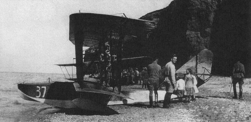
M-5 “37” Black Sea 1916.
The installed armament consisted of a Maxim, Vickers or Lewis machine gun installed on a bracket in front of the right-hand post usually with 450 rounds and an assortment of 8 kg or two 50 kg bombs. Small hand bombs could be carried in the cockpit and heavier ones could be hung under the wing. Starting in November, radio-telegraphy stations with a range of 40 km and Potte cameras (designed by Russian Army Sub-Colonel VF Potte) were installed on some. It was a 9-kg semi-automatic camera of weight with a lens of 21 cm of focal length and cassettes for 50 photos of 13 x 18 cm.)
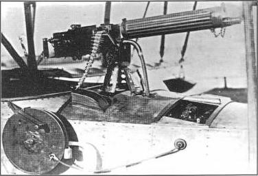
Maxim machine gun installed on an M-5 of the Black Sea Fleet.
In the Black Sea Fleet the M-5 model saw the most active use. By 1915 this force had outdated Curtiss F flying boats, which due to their performance and length of service were much inferior even to the Grigorovich M-4, of which two had been received. For this reason, the arrival of the first M-5 on May 16, 1915 was very well received. Soon this would generate an order for 12 serial copies. In total during the operational period of this flying boat in the Black Sea Fleet 71 were received.
In 1916 the naval pilots of the Black Sea receivef instruction called “Fight in the air” in which the combat methods of the M-5 were defined. The authors considered that the position of the machine gun on the M-5 guaranteed an excellent firing sector to the front, up and to the right. To the left it was only possible to cover about 60º. For this reason, M-5 crews were recommended to operate in pairs, with the second flying boat to the left and above the leader. At a distance of about 500 meters the first machine was to open fire in short salvos of 15-20 projectiles and upon reaching 100-150 meters begin continuous fire. In case the machine gun jammed, the crew had to use their Mauser pistols or Nagan revolvers.
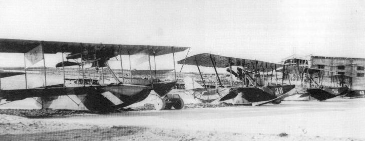
M-5 numbers 38, 56 and 43 next to Schetinin Curtiss F with number 72 at the naval station in the Kruglaya Bay in Sevastopol.
The aircraft of the Black Sea Fleet were based in Sevastopol, serving in the 1st and 2nd brigades of the air division, in Odessa and in Batumi. A certain amount was delivered to the 1, 2 and 3 air brigades on the cruisers “Alexandr I” and “Nikolai I” (capable of transporting 14 aircraft) and sometimes in the “Almaz” and “Pamyat Merkurya”. Aircraft of these cruisers participated in raids on the Turkish and Bulgarian borders. The most significant was the attack on the Turkish port of Zonguldak on January 24, 1916. This was carried out by the ship of the line “Empress María”, the cruiser “Kagul” and the cruisers “Alexandr I” and “Nikolai I”. 14 seaplanes were used, of which 11 managed to hit the target. The attack was carried out under heavy cloud conditions and return fire from the ground. Despite this, and due to the direct impact of a bomb, it was possible to sink the transport ship “Irminhard”, damaging several smaller ships and port facilities.
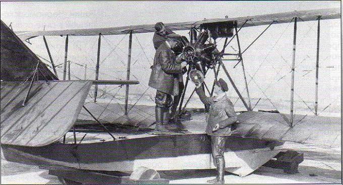
Repair of the Gnôme Monosoupape engine in an M-5
At the beginning of 1918 practically all the M-5 based in the Black Sea were in the zone occupied by the white troops or the Austrian interventionists. They continued to fly until 1919 – 1920.
On July 28, 1915, the Naval Aviation Officers’ School was opened in Petrograd. This center initially had four M-5 flying boats and two FBAs. Soon it was decided to open a branch of this school in Baku, on the Caspian Sea, which began operations on November 22, 1915.
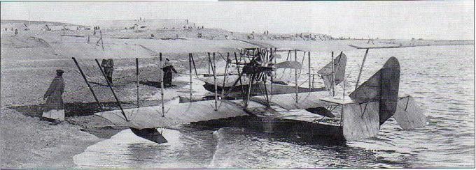
Two flying boats of the Baku Flying School on the shores of the Caspian Sea.
The total number of M-5 flying boats used by the Petrograd school is unknown, but evidence has been found that in 1918, when the decision was made to evacuate the school to Nizhni-Novgorod after the start of the war with Germany, there were five in flight conditions, which were evacuated.
That same number existed at the Trotsky school, opened on November 1, 1918, on Gutuyevskaya Island in Petrograd. In the period from May to October 1919, the M-5s of this school participated in combat actions against the army of General Yudenish, who was advancing towards Petrograd.
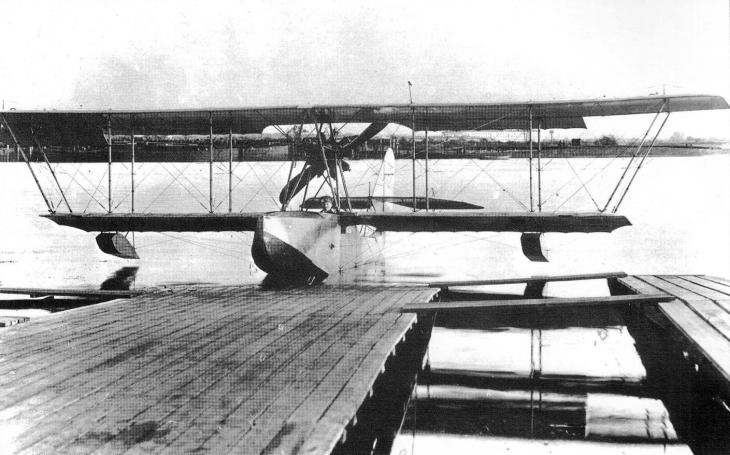
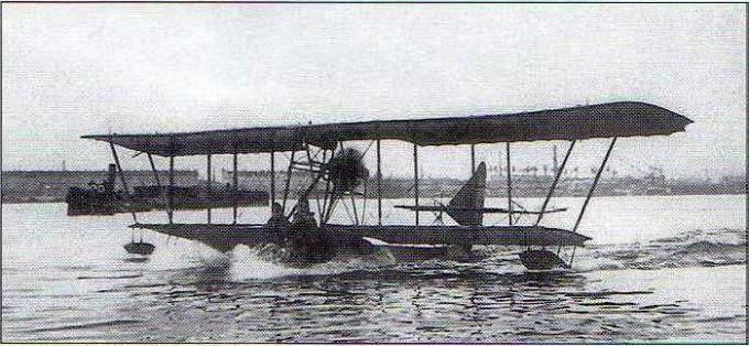
M-5 navigating the Neva River in Petrograd.
In December 1919 the two former schools were unified into the Aviation Military Naval School, which was transferred to the Volga River near Samara. The school was installed on a barge called “Yevpraksya” specially equipped with hangars and systems for raising and lowering seaplanes into the water. Between 1920 and 1921 and basically using the M-5, 44 naval pilots were trained. In December 1921 this school was transferred to Sevastopol, where some M-5 were used until the mid-20s. By December 1925 in the Soviet naval aviation there were 22 M-5 and M-20 (version with different engine plant.)
An M-5 flying boat launched in Baku in the winter of 1915.
Starting in 1917, the Baku branch became an independent training center equipped with excellent material conditions in terms of hangars, workshops and support systems for the operation of flying boats. Up to 20 M-5 were accumulated in this unit. Some of these flying boats participated in mid-1918 in the response to the Turkish offensive in the South Caucasus or Transcaucasia area. Active use resulted in most soon becoming unusable and by 1919 only two were still in flight condition. Due to the consequences of the Civil War, the school of naval pilots of Baku ceased to exist.
M-5 “7” Trotsky flight school on Gutuyevsky Island November 1918.
At least one M-5 flying boat was used in Finland after 1918 when it was found drifting at Kuokkala in 1918. This example was captured at Kuokkala in that year and remained in service with the Finnish Air Force until 1919, when it sank.
It is also known that at least one other fell into the hands of the Turks (possibly number 31 and delivered to the Black Sea Fleet on June 10, 1915), and is preserved to this day in the Hava Museci museum in Istanbul.
The M-5 was soon obsolete and was generally used as a training model. According to the evaluation of its pilots, the “Pyatak” (nickname assigned to the model and that could be translated as Little Fifth) was “pleasant” in flight, light and easily steerable. At sea it behaved well, being able to remain operational in rough seas with waves of 0.5 meters. The strong bottom allowed it to land directly on ice and snow and its excellent design made take-offs and landings easy.
On the other hand, its performance was not high. Flight speed was 100-105 km/h with a ceiling of only 3000 meters.
The M-5 basic production version was usually powered by a 100 hp Gnôme Monosoupape engine. Nearly 300 examples were produced at the Schetinin and Anatra factories before the Bolshevik triumph and later at Factory GAZ No.3 in Petrograd.
The 1916 М-10 version was characterized by maintaining the same Gnôme Monosoupape power plant and hull but with a reduced wing span which allowed the speed to be increased to 125 km/h. DP Grigorovich did not participate in the development of this version.
The М-20 1916 version was developed on the basis of the M-5 model with a new 120 hp Le Rhône power plant. A small series of 5 examples was built, characterized by a 40 cm shorter hull, which did not show great increases in performance.
Shortly after the German attack in 1941, the Soviet headquarters realized a need for transport gliders and ordered the development of several designs. Vladimir Gribovski agreed to design a light glider in two months and the tests of a prototype started on 1 September 1941. Given the Gribovsky designation G-29, it was accepted for production under the VVS designation G-11 (for Gribovski, 11-men including pilot).
G-11s were produced from late 1941 until mid-1942 in two factories: 138 were built in Shumerlya (factory no. 471) and 170 in Kozlovka village (factory no. 494), for a total of 308. Production restarted in 1944 at Ryazan remaining in production until 1948. From October 1944 the G-11U training glider with twin controls was also in production. There are no data for a total production number, but it is estimated that 500-600 were eventually completed.
A powered version designated G-11M by the VVS (Gribovsky designation G-30) had a M-11 radial engine mounted above the fuselage. It was tested from the Summer of 1942 but did not enter production. Design
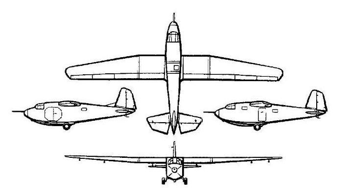
The G-11 was a high-wing, all-wooden construction, plywood-covered transport glider. The fuselage was rectangular in cross-section with a single-seat cockpit in the nose, accessed by an upward opening canopy. Behind the cockpit was the 3.24 m × 1.25 m × 1.36 m (10.6 ft × 4.1 ft × 4.5 ft) cargo hold / passenger cabin. There were two 1.2 m × 0.7 m (3.9 ft × 2.3 ft) doors on opposite fuselage sides. Later series had only one 1.4 m × 0.7 m (4.6 ft × 2.3 ft) hatch on the left side. Troops sat on folding benches along the sides, lit by two small rectangular windows on each side. Wings were three-part, fitted with flaps for landing and the landing gear was fixed, but could be folded by the pilot in order to shorten the landing, using the main fuselage skid for landing. Operational history
G-11s, along with the Antonov A-7 constituted a majority of Soviet transport gliders. They were mainly used from mid-1942 for supplying Soviet partisans with provisions, weapons, equipment and trained men, towed mainly by SB or DB-3 bombers. Most intensive use was from March to November 1943 in Belarus, in the Polotsk-Begoml-Lepel area, on the Kalinin Front. Several hundred Soviet gliders (of all types) were used in night supply flights there. After landing, the gliders were destroyed and pilots were sometimes returned by aircraft. The only known instance of a glider returning from the field occurred in April 1943, when a famous glider and test pilot Sergei Anokhin evacuated two wounded partisan commanders in a G-11, towed by a Tupolev SB bomber, piloted by Yuriy Zhelutov, on a 10 m (33 ft) short towrope.
Gliders were also used to supply partisans in some areas in 1944 and to transport sabotage groups behind enemy lines. G-11 gliders were also used in at least one small-scale airborne operation, the Dnepr crossing, carrying anti-tank guns and mortars.
A less typical action was an airbridge from Moscow to the Stalingrad area in November 1942, to rapidly deliver anti-freeze coolant for tanks, during the battle of Stalingrad.
The G-11 enjoyed relative success as a light transport glider design, having more capacity than the Antonov A-7, and its transport compartment was a better fit for cargo, although light guns could only be carried in parts due to small hatches.
Wingspan: 18 m (59 ft 1 in) Length: 9.8 m (32 ft 2 in) Height: 2.7 m (8 ft 10 in) Wing area: 30 m2 (320 sq ft) Empty weight: 1,200 kg (2,646 lb) Gross weight: 2,400 kg (5,291 lb) Never exceed speed: 280 km/h (170 mph, 150 kn) (aerotow) Aerotow speed: 146 km/h (91 mph; 79 kn) Rate of sink: 2.2 m/s (430 ft/min) Lift-to-drag: 16:1 Wing loading: 83 kg/m2 (17 lb/sq ft) Crew: 1 Capacity: 10 troops or cargo / 1,200 kg (2,646 lb)
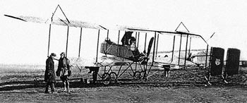
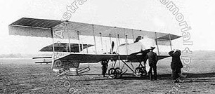
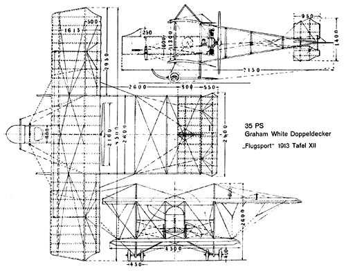
The Grahame-White Type XV (sometimes called “Bi-Rudder ‘Bus” or “Box-Kite” of 1915 was directly derived from the Type XII.
The aircraft itself was a pod-and-boom configuration biplane with three-bay un-staggered wings. In early models, two seats were fitted on the leading edge of the lower wing for the instructor and the trainee pilot; in later models, space was provided for them in tandem in an open-topped nacelle, with the engine mounted pusher-fashion behind them. The empennage was carried on four parallel beams extending two each from the top and bottom wings, and consisted of twin rudders and a horizontal stabiliser and elevator that were carried on the top two beams. Early production aircraft had wings of equal span, but later examples had long extensions fitted to increase the span of the upper wing. The landing gear comprised two separate, wing-mounted, ‘two-wheel plus skid’ assemblies and a tail-skid.
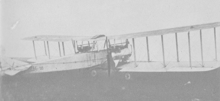
This military trainer biplane was built in quantity for the RNAS (as the Admiralty “Type 1600”) and later the RFC, for a total of 135 aircraft. It was known as the Admiralty Type 1600, since the first aircraft of the type purchased for the Royal Naval Air Service was given that serial number, and contemporary practice was to assign type numbers based on the serial number of the first example in service.
First flying in 1913, there were notable differences between the early and late examples produced, but they retained the same designation. They were made in a variety of forms from 1912 – 17, undergoing a gradual evolution, losing the front elevator and having a cockpit nacelle, aileron balance cables, top wing extensions and dual controls fitted. The Type XV can also be found as the “G.W.15” in some sources.
60hp Le Rhone, 70 & 80hp Gnome and 60hp Green engines were among those used to power the huge variation of types built under the general umbrella name of GW XV.
The Type XV was extensively used as a trainer by both the RNAS and RFC, with 135 machines being purchased for this purpose. In November 1913, one RFC Type XV was employed in the first British trials of firing a machine gun (a Lewis gun) from an aircraft at targets on the ground. Despite the number of aircraft produced, little documentation on the type has survived.
The XV trainers were the type used by No. 65 Squadron RFC, and 48 Reserve Sqn at Waddington from November 1916 to June 1917, as they were established for 18 machines, and A1700 was definitely on their charge. Along with Farman Shorthorns they were the first aircraft based here.
The Type XV was also operated by the Australian Flying Corps at Central Flying School, Point Cook, Victoria, Australia.
GW XV, c.1916
Three Type XVs survived the First World War to become civil aircraft, being some of the first aircraft to bear British aircraft registrations once civil flying was permitted in 1919.
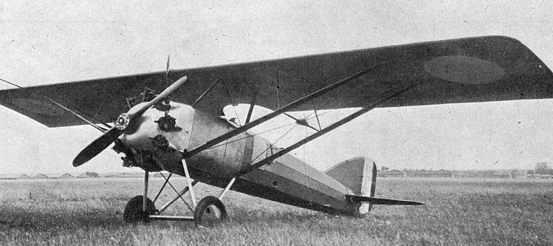
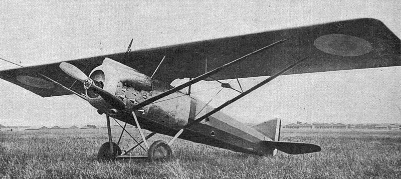
The GL-30 was a parasol-wing monoplane with retractable undercarriage and a Bristol Jupiter engine. Like most of Gordou-Lesserre’s earlier aircraft, it was a parasol wing design but its planform was trapezoidal rather than rectangular. In 1923 it flew the Coupe Beaumont course at an impressive 360 km/h (220 mph; 190 kn).
The GL.30 was the basis of a new fighter, the GL.31, which had a greater span, almost double the wing area, a fixed undercarriage, and a Gnome-Rhône 9A engine. It was armed with four machine guns, two in the forward fuselage and two in the wings. The GL. 31 was not flown until 1926 and then abandoned, overtaken by the GL.32, the company’s entry in a 1923 Aéronautique Militaire competition to select a new fighter. It returned to a rectangular plan wing.
By the time this prototype flew, the Gourdou-Leseurre had been acquired by Loire, and therefore the new aircraft was entered as the LGL.32. Placed second in the trials, the type’s performance was impressive enough to still result in an order in January 1927 for a small batch of aircraft – five evaluation aircraft and 20 preproduction machines. Eventually, 475 of this basic version, dubbed LGL.32C.1 in service, would be ordered by the Aéronautique Militaire and 15 more by the Aéronautique Maritime. Romania ordered a further 50 aircraft of the same design as the examples in French service, Turkey ordered 12 (these designated LGL.32-T) and another one may have been purchased by Japan.
LGL.32 Hy May 1927
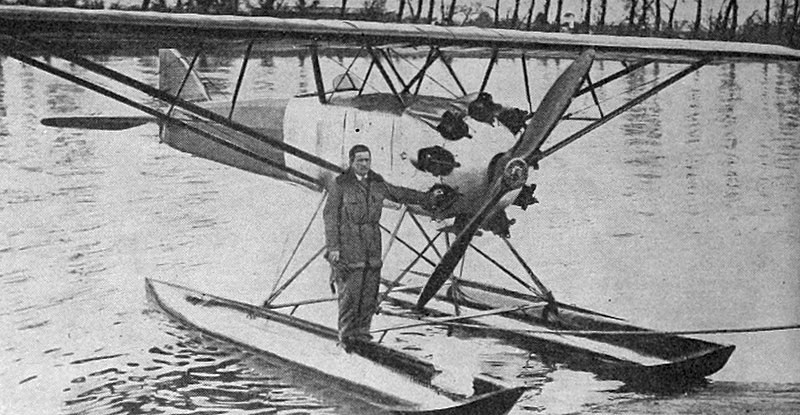
The LGL.32 Hy was a twin-pontoon floatplane version converted from the LGL.32 prototype. It set a world seaplane altitude record on 28 March 1927.
In French service, development turned from fighters to adapting the aircraft as a carrier-borne dive bomber. These featured general strengthening of the airframe, divided main undercarriage units, and a “fork” under the fuselage able to release a 50 kg (110 lb) bomb from under the fuselage while avoiding hitting the propeller.
While prolific, the GL.32 was not long-lasting, and attrition took a heavy toll on them. By 1934, all remaining examples were relegated to training and as instructional airframes; at the start of 1936, only 135 remained of the original 380 purchased. A number of these were sold to the government of the Second Spanish Republic and to the autonomous Basque Government. Another aircraft was supplied to the Basques in 1937, modified as a dive bomber along the lines of the previous French experiments. Designated the GL.633, this aircraft was used by Miguel Zambudio to attack the Nationalist battleship España, scoring decisive hits that contributed substantially to her subsequent sinking.
GL.30 Racer with retractable undercarriage and Engine: Bristol Jupiter one built
GL.31 / GL.31C.1 / CL-I-3 Four-gun fighter prototype with fixed undercarriage longer-span wings engine: Gnome-Rhône 9A one built
LGL.32 / GL.32C.1 Definitive two-gun fighter version Powerplant: 1 × Gnome et Rhône 9A Jupiter VIII, 450 kW (600 hp) Propeller: 2-bladed wooden fixed pitch Wingspan: 12.2 m (40 ft 0 in) Wing area: 24.9 m2 (268 sq ft) Length: 7.55 m (24 ft 9 in) Height: 2.95 m (9 ft 8 in) Empty weight: 963 kg (2,123 lb) Gross weight: 1,376 kg (3,034 lb) Fuel capacity: 285 kg (628 lb) – (ca. 200 L (53 US gal; 44 imp gal)) Maximum speed: 270 km/h (170 mph, 150 kn) at sea level Maximum speed: 260 km/h (160 mph; 140 kn) at 3,000 m (9,800 ft) Maximum speed: 251 km/h (156 mph; 136 kn) at 5,000 m (16,000 ft) Maximum speed: 215 km/h (134 mph; 116 kn) at 8,000 m (26,000 ft) Landing speed: 90 km/h (56 mph; 49 kn) Range: 500 km (310 mi, 270 nmi) Service ceiling: 9,700 m (31,800 ft) Time to 2,000 m (6,600 ft): 3 minutes 5 seconds Time to 5,000 m (16,000 ft): 11 minutes Time to 8,000 m (26,000 ft): 31 minutes Wing loading: 54.8 kg/m2 (11.2 lb/sq ft) Power/mass: 0.33 kW/kg (0.2 hp/lb) Armament: 2x 7.7 mm (0.303 in) Vickers or Darne machine-guns – fuselage / 2x 7.7 mm (0.303 in) Darne machine-guns in wings Crew: 1 ca. 490 built
LGL.32.01 The first prototype.
LGL.32T Export version for Turkey 12 built
LGL.32 Hy Twin-pontoon floatplane version converted from LGL.32 prototype. one converted
LGL.321 LGL.32 converted to use 450 kW (600 hp) version of the Gnome & Rhône 9Ac one converted
LGL.323 LGL.32 converted to use supercharged 373 kW (600 hp) Bristol Jupiter for unsuccessful altitude record attempts. one converted
LGL.324 LGL.323 further modified and used by Pierre Lemoigne to set world landplane altitude record 500 kg payload of 9,600 m (31,500 ft) on 23 May 1929 Albert Lécrivain set world landplane altitude record 11,000 m (39,090 ft) on 24 October one converted
LGL.33 / LGL.33C.1 Similar to LGL.32 revised wing struts, landing gear, and tail Engine: Lorraine 12Eb one built
LGL.34 / LGL.34C.1 Similar to LGL.32 Engine: Hispano-Suiza 12Gb one built
LGL.341 similar to LGL.32 Engine: Hispano-Suiza 12Hb two built, second with revised radiator arrangement
LGL.351 Engine: Renault 12J one built
LGL.390 night fighter prototype Engine: Hispano-Suiza 9Va one converted from LGL.32
GL.410 modernised fighter with divided main undercarriage one built
GL.430 strengthened carrier-borne dive-bomber prototype one built
GL.432 dive-bomber variant similar to GL.430 used for operational testing four built
GL.450 fighter version
GL-482 fighter version Engine: Hispano-Suiza 12Xbrs one built
GL.521 dive-bomber version taller tail fin Engine: Gnome-Rhône 9Kfr two built
After the fall of France the French Gnome-Rhone 14M radial engine became available to the Germans in large numbers, and the Go 242 was modified to serve as the Go 244 twin-engined transport, each of the twin booms being extended forward of the leading edge of the wing to mount one of these engines. At the same time fixed tricycle landing gear was installed.
A total of 133 conversions was made from the five Go 242B variants and these were designated correspondingly Go 244B-1 to B-5. First deliveries were made in March 1942 to the Greek-based KGrzbV 104 and to KGrzbV 106 in Crete, but they proved to be relatively easy targets for Allied fighter aircraft and had been withdrawn by November 1942. Some Go 244s had 492kW BMW 132Z or captured Russian Shvetsov M-25As each of 559kW.
Go-244B-2 Engine: 2 x Gnome-Rhone 14M, 522kW Max take-off weight: 7800 kg / 17196 lb Empty weight: 5100 kg / 11244 lb Wingspan: 24.5 m / 80 ft 5 in Length: 15.80 m / 51 ft 10 in Height: 4.70 m / 15 ft 5 in Wing area: 64.4 sq.m / 693.20 sq ft Max. speed: 290 km/h / 180 mph Ceiling: 7500 m / 24600 ft Range: 600 km / 373 miles Armament: 4 x 7.9mm machine-guns
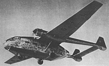
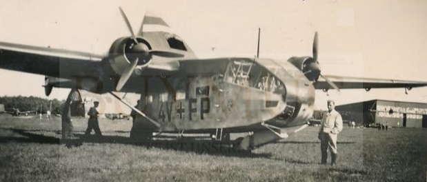
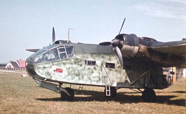
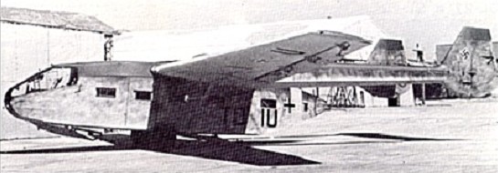
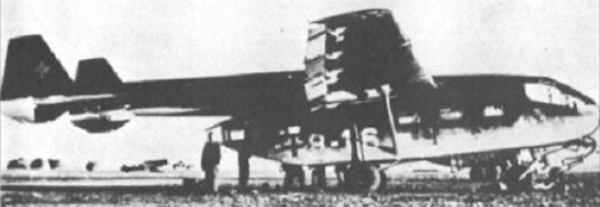
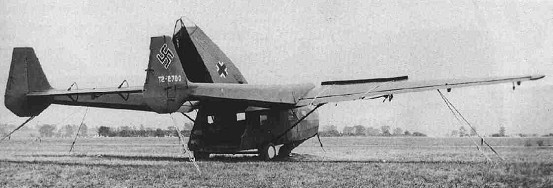
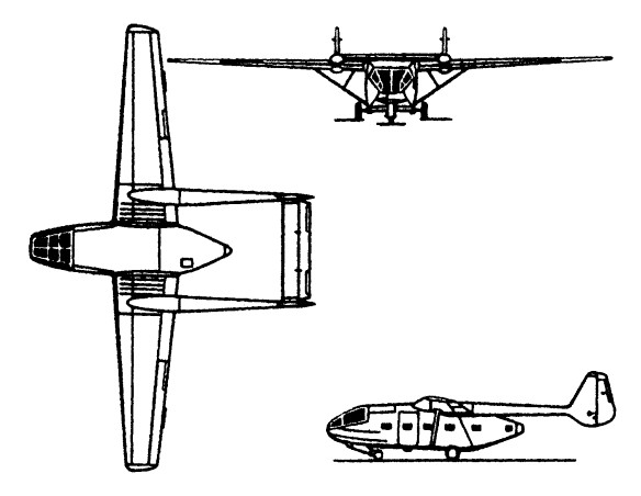
The work of Dipl. Ing Albert Kalkert, the Gotha Go 242 assault glider was developed with the approval of the Reichs-luftfahrtministerium since it offered almost three times the troop-carrying capacity of the DFS 230 then in use. The fuselage pod was of steel tubular construction with fabric covering, and carried jettisonable landing gear and two retractable skids. The wings were made of wood with fabric and plywood covering.
The aircraft could carry 21 fully-equipped troops, or equivalent weight in military loads, such as a Kubelwagen utility vehicle, loaded through the hinged rear fuselage. Two prototypes were flown in 1941 and production followed permitting entry into service in 1942. The type’s operational debut was made in the Mediterranean and Aegean theatres, Go 242 units being based in Greece, Sicily and North Africa. Heinkel He 111 tugs were usually employed and rocket-assisted take-off equipment could be fitted, the variety of propulsion units including four 500kg Rheinmetall-Borsig RI-502 solid fuel rockets. Production totalled 1,528 aircraft. 133 were modified into Go-244.
Go-242 Max take-off weight: 6800-7300 kg / 14992 – 16094 lb Empty weight: 3200 kg / 7055 lb Wingspan: 24.5 m / 80 ft 5 in Length: 15.8 m / 51 ft 10 in Height: 4.25 m / 13 ft 11 in Wing area: 62.4 sq.m / 671.67 sq ft Armament: 4 x 7.9mm machine-guns
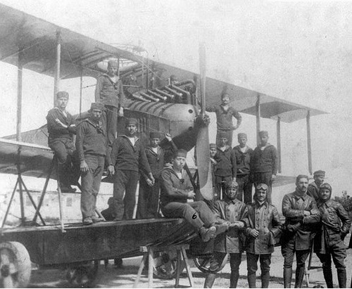
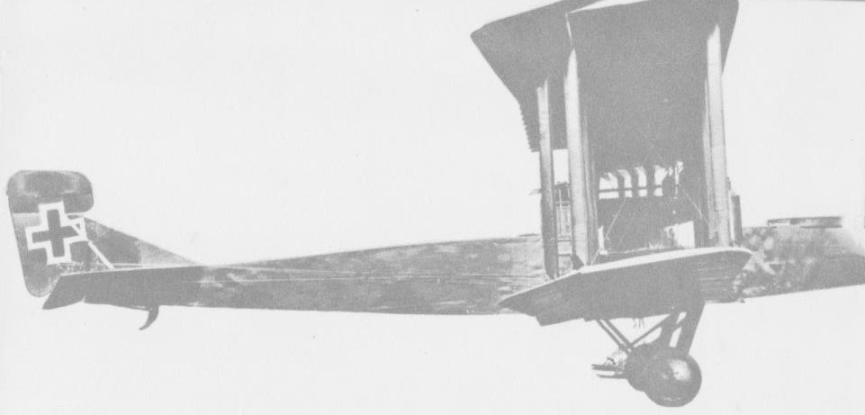
The Gotha WD.2 (for Wasser Doppeldecker – “Water Biplane”) and its derivatives were a family of military reconnaissance aircraft produced in Germany just before and during the early part of World War I. It was a development of the Avro 503 that had been built under licence by Gotha as the WD.1, and like it, was a conventional three-bay biplane with tandem, open cockpits. The landing gear comprised twin pontoons and dispensed with the small pontoon carried under the tail of the WD.1. Machines built for the German Navy were unarmed, but those supplied to the Ottoman aviation squadrons carried a 7.92 mm (.312 in) machine gun in a ring mount on the upper wing, accessible to the observer, whose seat was located directly below it.
In an attempt to increase performance, one WD.2 was built with a reduced wingspan and its Benz Bz.III engine replaced with the more powerful Mercedes D.III. Designated the WD.5, no further examples were built in this configuration, but it served as the pattern for the WD.9, built in a small series. This differed from the WD.5 prototype in having a trainable 7.92 mm (.312 in) machine gun located in the rear cockpit, to which the observer had been relocated. One such aircraft was supplied to the German Navy, with the rest of the batch going to Turkey, albeit with the less powerful engine of the WD.2.
The last member of the family to be built in any quantity was the D.III-powered WD.12, an unarmed version which featured greater attention to streamlining the aircraft, most especially around the engine area, which was now provided with a close-fitting cowl and a spinner for the propeller. Again, this type was supplied to both Germany and the Ottoman Empire. It was followed in production by a small number of WD.13s, essentially similar but for the use again of the less powerful Bz.III.
Finally, two WD.15s were built after a considerable redesign of the aircraft. These had plywood-covered fuselages, as opposed to the fabric covering used on all earlier members of the family, and were fitted with Mercedes D.IVa engines.
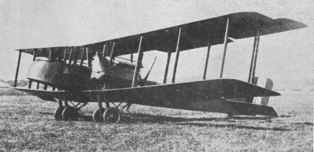
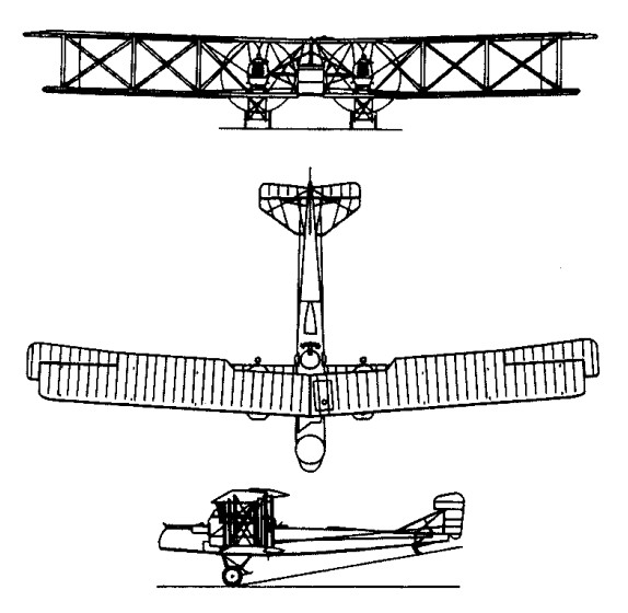
Operational use of the G.IV demonstrated that the incorporation of the fuel tanks into the engine nacelles was a mistake. In a crash landing the tanks could rupture and spill fuel onto the hot engines. This posed a serious problem because landing accidents caused 75% of operational losses. In response Gothaer produced the G.V, which housed its fuel tanks in the center of the fuselage. The smaller engine nacelles were mounted on struts above the lower wing.
The G.V was a three-bay biplane with wings of two-spar wooden construction, with plywood covering of the centre section of the lower wing and fabric covering over the remainder. The wooden fuselage has plywood covering. Conventional control surfaces are fabric covered steel tube construction. Ailerons are on all four wings and each undercarriage unit has twin wheels.
The Gotha G.V pilot seat was offset to port with the fuel tanks immediately behind. This blocked the connecting walkway that previously on earlier machines allowed crew members to move between the three gun stations. All bombs were carried externally in this model. The Gotha included an important innovation in the form of a “gun tunnel” whereby the underside of the rear fuselage was arched, allowing placement of a rearward-facing machine gun protecting from attack from below, removing the blind spot.
The base variant of G.V offered no performance improvement over the G.IV. The G.V was up to 450 kg (990 lb) heavier than the G.IV due to additional equipment and the use of insufficiently seasoned timber. The Mercedes D.IVa engines could not produce the rated 190 kW (260 hp) due to inferior quality of fuel.
The G.V entered service in August 1917. For the performance reasons aforementioned, it generally could not operate at altitudes as high as the G.IV. On 13 June 1917 London was raided in daylight by 14 Gothas against little opposition. As the RFC formed home defence squadrons, after one final raid by 22 Gothas on 7 July 1917, the raiders switched to night bombing.
G.Va In February 1918, Gothaer tested a compound tail unit with biplane horizontal stabilizers and twin rudders. The new tail unit, known as the Kastensteuerung, improved the aircraft’s marginal directional control on one engine. The resulting G.Va subvariant incorporated the new tail as well as a slightly shorter forward fuselage with an auxiliary nose landing gear. All 25 G.Va aircraft were delivered to Bogohl 3, the new designation for the former Kagohl 3.
G.Vb Carried an increased payload comparing to the earlier G.Va, and operated at a maximum takeoff weight of 4,550 kg (10,030 lb). To reduce the danger of flipping over during landing, Gothaer introduced the Stossfahrgestell (“shock landing gear”), a tandem two-bogie main landing gear. The Stossfahrgestell proved so good that it was fitted to all G.V’s in Bogohl 3. Some G.Vb aircraft also had Flettner servo tabs on the ailerons to reduce control forces.
Idflieg ordered 80 G.Vb aircraft, the first being delivered to Bogohl 3 in June 1918. By the Armistice, all 80 aircraft were built but the last batch did not reach the front and was delivered direct to the Allied special commission.
Engines: 2 x Mercedes D.IVa, 260 hp Wingspan: 77 ft 9 in Wing area: 963.4 sq.ft Length: 38 ft 11 in Height: 14 ft 1.25 in Empty weight: 6040 lb Take-off weight: 8763 lb Max speed: 87 mph at SL Range: 520 mi Armament: 2 x mg Bombload: 660-1100 lb
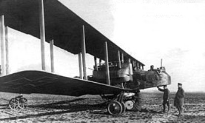
The Gotha G.IV was a development of the G.III. The blunt nose made it possible to place the engines closer together, and together with placing the tailfins in the slipstream this gave better one-engine performance making it possible to run the engine at full power. But none of the type G twin-engined biplanes could fly level on one engine. The Gotha G was a ‘tunnel’ in the bottom of the tail that made it possible for the tail gunner to cover the lower rear of the aircraft.
Gotha G.IV
Later versions had biplane tails with twin fins and eliminated the position for the nose gunner.
Gotha G-IV
The G.IV (also produced by LVG and Siemens-Schuckert) was used in the first mass attack on England, when 21 Gothas raided Folkestone, Shorncliffe and elsewhere on 25 May 1917, killing about 95 people and injuring many others. On 13 June 14 Gothas attacked London for the first time and caused the worst casualties (of an air raid) of the war, with 162 people being killed and 432 injured. The heavy casualties suffered among the civilian population of England by these raids forced the return of aircraft from France to defend the cities, and such was their success that the last big raid on England during daylight hours was carried out on 12 August.
G.IV Engine: 2 x 260hp Mercedes D.IVa Take-off weight: 3975 kg / 8763 lb Empty weight: 2740 kg / 6041 lb Wingspan: 23.70 m / 77 ft 9 in Length: 11.86 m / 38 ft 11 in Height: 4.30 m / 14 ft 1 in Wing area: 89.50 sq.m / 963.37 sq ft Max. Speed: 140 km/h / 87 mph Cruise speed: 124 km/h / 77 mph Ceiling: 6500 m / 21350 ft Range: 522 km / 324 miles Crew: 3