Grumman J2F Duck / OA-12 / JF / G-15

J2F Duck

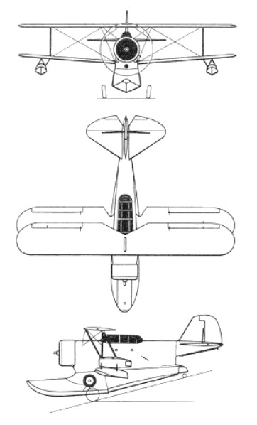
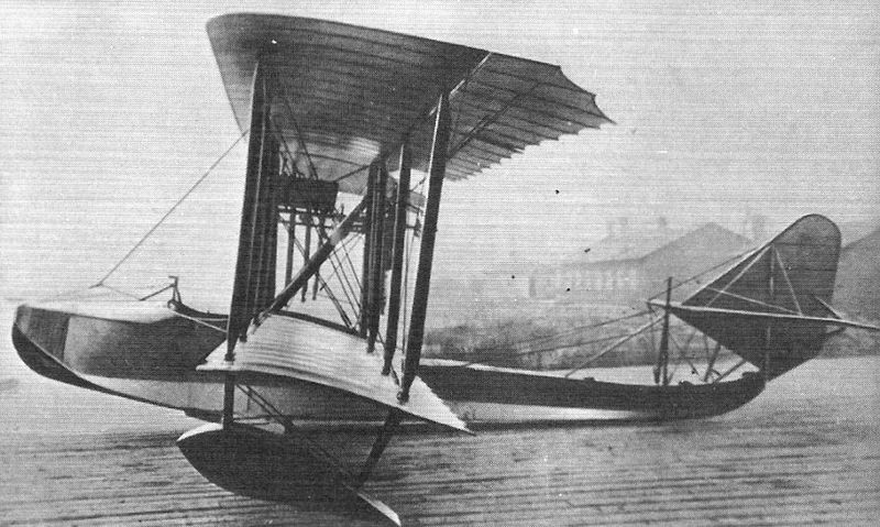
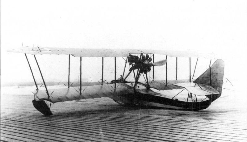
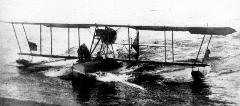
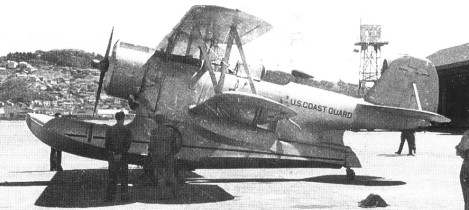
The J2F was an equal-span single-bay biplane with a large monocoque central float which also housed the retractable main landing gear, a similar design to the Leroy Grumman-designed landing gear first used for Grover Loening’s early amphibious biplane designs, and later adopted for the Grumman FF fighter biplane. The aircraft had strut-mounted stabilizer floats beneath each lower wing. A crew of two or three were carried in tandem cockpits, forward for the pilot and rear for an observer with room for a radio operator if required. It had a cabin in the fuselage for two passengers or a stretcher.

The Duck’s main pontoon was blended into the fuselage, making it almost a flying boat despite its similarity to a conventional landplane which has been float-equipped. This configuration was shared with the earlier Loening OL, Grumman having acquired the rights to Loening’s hull, float, and undercarriage designs. Like the F4F Wildcat, its narrow-tracked landing gear was hand-cranked.

Production of this general utility amphibian began in 1933 when the first prototype flew, and production continued until 1945. In all, nine series of the Duck were built.

The J2F-1 Duck first flew on 2 April 1936, powered by a 750 hp (559 kW) Wright R-1820 Cyclone, and was delivered to the U.S. Navy on the same day. The J2F-2 had an uprated Wright Cyclone engine of 790 hp (589 kW). Twenty J2F-3 variants were built in 1939 for use by the Navy as executive transports with plush interiors. Due to pressure of work following the United States entry into the war in 1941, production of the J2F Duck was transferred to the Columbia Aircraft Corp of New York. They produced 330 aircraft for the Navy and U.S. Coast Guard. If standard Navy nomenclature practice had been followed, these would have been designated JL-1s, but it was not, and all Columbia-produced airframes were delivered as J2F-6s.

The first appeared for the Navy in 1933 as the JF-1, powered by a 521.6kW Pratt & Whitney R-1830 Twin Wasp engine. This was followed by the JF-2 Coast Guard version, powered by a 559kW Wright Cyclone radial, and the JF-3.

The amphibian was originally used for photography, target-towing, scouting, and rescue work. Although the Duck is normally flown as a two-seater in tandem fashion, a folding floor in the rear cockpit gives access to a lower compartment for use in rescue work and the like; the lower compartment could house either two extra crew members or a stretcher.

A number of JF-2s were also delivered to Argentina.

By the beginning of 1941 about 115 JF and J2F-1 (company designation G-15) to J2F-4 Ducks were in service as general/utility amphibians for photographic, target-towing, scouting and rescue work. The J2F was an improved version of the earlier JF Duck, with its main difference being a longer float.

These were followed by J2F-5s and J2F-6s. The J2F6 was by far the most common. It featured aerodynamic improvements over the previous models, including a long-cord engine cowling.

The J2F-6 was produced in 1944 by the Columbia Aircraft Corporation of Valley Stream, Long Island, under licence from Grumman, bringing the total number of JF/J2Fs built to over 600.

J2F-6

J2Fs of the utility squadron of US Patrol Wing 10 were destroyed at Mariveles Bay, Philippines, by a Japanese air raid on 5 January 1942. The only Duck to survive the attack had a dead engine but had been concealed at Cabcaben airfield during the Battle of Bataan, to be repaired afterwards with a cylinder removed from a destroyed J2F-4 submerged in Manila Bay. Following repairs the J2F-4 departed after midnight on 9 April 1942, overloaded with five passengers and the pilot, becoming the last aircraft to depart Bataan before the surrender of the Bataan to the Japanese only hours later. Among its passengers was Carlos P. Romulo (diplomat, politician, soldier, journalist, and author), who recounted the flight in his 1942 best-selling book I Saw the Fall of the Philippines (Doubleday, Doran & Company, Inc., Garden City, New York 1943, pp. 288–303), for which he received the Pulitzer Prize for Correspondence.

Several surplus Navy Ducks were converted for use by the United States Air Force in the air-sea rescue role as the OA-12 in 1948.

The Argentine Naval Aviation received four new-build Grumman G-15s (equivalent to J2F-4s) in 1939, to supplement the eight Grumman G-20s (export version of the Grumman JF-2) received in 1937. In 1946–1947, 32 ex-US Navy Ducks (consisting of one J2F-4, 24 J2F-5s, and 7 J2F-6s) were acquired, with the last examples remaining in use until 1958.

The Colombian Navy operated three examples from 1948.

The Mexican Navy operated three ex-U.S. Navy J2F-6s from 1950–1951.

The Peruvian Navy operated one ex-USN example from 1961–1964.

In the United States the United States Army Air Forces, United States Coast Guard, United States Marine Corps, and United States Navy all operated the J2F.

USCG Northwind March 1947 Wellington New Zealand – Grumman J2F-6 Duck & Sikorsky HNS-1

A Grumman J2F-6 Duck was owned and operated by Kermit Weeks at Fantasy of Flight in Polk City, Florida.

The United States Coast Guard worked with North South Polar, Inc. to recover a J2F-4 Duck, serial number V-1640, downed in a storm on a Greenland glacier on 29 November 1942. Two Coast Guard airmen were lost along with a rescued U.S. Army Air Forces passenger from a downed B-17 searching for a downed C-53 with five on board. The three men of the Duck are presumed to still be entombed at the site. North South Polar, under the auspices of the Coast Guard team, located the aircraft in August 2012 resting 38 feet beneath the surface of the ice sheet.

Variants:

J2F-1
Initial production version with 750 hp R-1820-20 engines, 29 built.

J2F-2
United States Marine Corps version with nose and dorsal guns and underwing bomb racks, 21 built.

J2F-2A
As J2F-2 with minor changes for use in the United States Virgin Islands, nine built.

J2F-3
J2F-2 but powered by an 850 hp R-1820-26 engine, 20 built.

J2F-4
J2F-2 but powered by an 850 hp R-1820-30 engine and fitted with target towing equipment, 32 built.

J2F-5
J2F-2 but powered by a 1,050 hp R-1820-54 engine, 144 built.
Engine: 1 × Wright R-1820-54 nine-cylinder radial engine, 900 hp (670 kW)
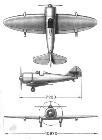
Wingspan: 39 ft 0 in (11.9 m)
Wing area: 409 ft² (38 m²)
Length: 34 ft 0 in (10.37 m)
Height: 13 ft 11 in (4.25 m)
Empty weight: 5,480 lb (2,485 kg)
Loaded weight: 7,700 lb (3,496 kg)
Maximum speed: 190 mph (304 km/h)
Cruise speed: 155 mph (248 km/h)
Stall speed: 70 mph (112 km/h)
Range: 780 mi (1,255 km)
Service ceiling: 20,000 ft (6,100 m)
Rate of climb: ft/min (m/s)
Crew: two (pilot and observer)
Capacity: two rescued airmen
Armament: 1 × Browning .30 cal machine gun (7.62 mm) on flexible mount in rear cockpit
Bombload: 650 lb (295 kg)

J2F-6
Columbia Aircraft built version of the J2F-5 with a 1,050 hp R-1820-64 engine in a long-chord cowling, fitted with underwing bomb racks and provision for target towing gear; 330 built.

OA-12
Air-sea rescue conversion for the United States Army Air Forces (and later United States Air Force, OA-12A).

Grumman E-2 Hawkeye / W2F-1

E-2C Hawkeye

The first of three Hawkeye prototypes flew on October 21, 1960, the Hawkeye became the primary early warning component of the US Navy carrier air wings.

Grumman E-2 Hawkeye Article

Delivery of the first member of the Hawkeye family, the E 2A (formerly known as the W2F-1) began on 19 January 1964 to the US Navy, entering service in 1965 as a replacement for the Grumman E 1B Tracer, an early warning derivative of the S 2 Tracker. The E 1B carried its radar aerial inside a fixed oval, aerofoil shaped radome, but the E 2 was the first AEW type to adopt the 7.32m diameter ‘rotodome’, with the antennae mounted rigidly inside a radome which itself rotates at 6 rpm in the case of the Hawkeye. Fifty nine E 2As were delivered to the US Navy, and the type quickly proved its worth off the coast of Vietnam. The Hawkeyes were sent out to patrol whenever there was a risk of the naval task force being attacked by enemy aircraft or ships; by extending the force’s detection range well beyond the normal horizon, even against low flying aircraft, the E 2As reduced the need for large numbers of intercepters to be kept on alert throughout the day and night.
In addition to their defensive role, the Hawkeyes were able to relay target information from the aircraft carriers to their distant attack formations. With the E 2A the US Navy began to appreciate the many advantages of a modern AEW aircraft, but the 1950s technology computer had to be physically modified every time the ATDS (Airborne Tactical Data System) needed new software. To overcome this problem the Hawkeyes were fitted with Litton L 304 general purpose digital computers, and several minor modifications were also made; the E 2As thus became E 2Bs, which flew for the first time in February 1969, all having been converted by 1971.
Grumman built 56 E-2As, later updated to E-2B, before introducing the E-2C. The first of the significantly more capable E-2C series flew in January 1971. By mid-1987 97 E-2Cs had been delivered to the US Navy, plus 21 to overseas customers.

Firm orders existed for a total of 47 aircraft, with procurement of 36 more by the end of 1985. Israel has four and in 1979 Japan released funds for the first four of an eventual total of about 15 for the JASDF. The Air Self-Defence Force accepted its first E-2C Hawkeye at Bethpage, Long Island, on 18 May 1982.

The E-2G has an advanced radar that is capable of detecting airborne targets anywhere in a three-million-cubic-mile surveillance envelope. It first entered service with the US Navy in November 1973 and went to sea on board USS Saratoga in late 1974. A training version is designated TE-2C.

By this time the first E 2Cs were flying, the prototype first flew in January 1971. Although virtually identical to its forebears externally, the E 2C is a very different under the skin. The improved APS 120 radar’ can detect and track aircraft over land as well as above the sea, and the APS 125 ARPS (Advanced Radar Processing System) is being incorporated in all E 2Cs to give long range detection of very small targets and automatic overland tracking. The APS 125 also incorporates a digital airborne moving target indicator (AMTI) in place of the E¬2B’s analogue unit. Communication equipment has been improved, and the E 2C has better hot day and single engine performance than its predecessors, and is four times as reliable.

E-2C

The E 2C entered service in 1974, its arrival more or less coinciding with the introduction of the US Navy’s new generation of carrier based aircraft: the F 14 Tomcat, S 3 Viking, EA 6B Prowler and A 6E Intruder.
The latest APS-138 surveil¬lance radar was introduced on the E-2C airborne early warning aircraft built in 1983, and will be retrofitted to earlier E-2Cs in place of the original APS-125. APS-138 has a low-¬side-lobe active-element-array antenna, an enhanced passive detection system with trian¬gulation and exotic emitter recognition, together with expanded computer memory allowing the simultaneous and automatic track¬ing of up to 600 targets. At an operating height of 9,150m (30,000ft), a Hawkeye can detect and assess any approaching aircraft over a range of 480km (260 nm) in all weathers.
From 1988 new E-2Cs will be fitted with uprated Allison T56-A-427 engines, and will receive the improved APS-139 radar system which can transmit on any one of ten UHF channels. General Electric is also developing an APS-145 radar for service in 1990 which will counteract the problem of overland clutter.
The Hawkeyes work closely with the Tomcats, orbiting on station between 110 km (68 miles) and 185 km (115 miles) from the carrier at heights of 4600 m to 9150 m (15000-¬30000 ft); a typical orbit begins at 7000 m (23 000 ft) and rises to 8500 m (28000 ft) as fuel is burnt off. At a height of 7600 m (24 930 ft) the radar has a horizon range of 375 km (235 miles) and can detect high flying aircraft out to 460 km (285 miles).
The radar can detect and track more than 200 targets simultaneously, supplying alti¬tude, range and velocity information. The crew of five includes three operators in the combat information centre, each of which has a main 25 cm (10 in) radar display and a 12.5 cm (5in) screen giving alphanumeric information. Targets detected by the AWG 9 long range fire control radar in the F 14 can be notified to an E 2C by data link; they are then correlated with the appropriate return on the Hawkeye’s own radar displays or are used to feed in new information, thus effec¬tively extending the range of the AEW cover-age. The intercepter may then be vectored automatically on to the rear of the target for a visual identification, or it can be manoeuvred into the optimum firing position. The US Navy claims that the use of an E 2C for airborne control can double the number of kills made by the intercepter force while substantially reducing losses of friendly air¬craft.
Hawkeyes can also control a carrier’s attack force, supplying navigation and turn¬ing instructions by data link.

Northrop Grumman undertakes production of E-2C Hawkeye in the Hawkeye 2000 form (first flown April 1998).

Gallery

E-2A Hawkeye

E-2B Hawkeye

E-2C Hawkeye
Engine: 2 x Allison T56-A-425 turboprop, 4910 shp.
Installed thrust: 6800 kW.
Span: 24.6 m.
Length: 17.5 m.
Wing area: 699.66 sq.ft / 65 sq.m.
Height: 18.34 ft / 5.59 m
Empty wt: 17,265 kg.
MTOW: 23,560 kg.
Max speed: 600 kph.
Cruising speed: 269 kts / 498 kph
Service Ceiling: 30840 ft / 9400 m.
Initial climb rate: 2519.69 ft/min / 12.80 m/s
T/O run: 609 m.
Ldg run: 439 m.
Fuel internal: 7050 lt.
Range: 320 km.
Endurance: 4 hr on station.
Air refuel: Yes.
Crew: 5

Engines: 2 x turbo-prop Allison T-56 A-8, 2980kW
Max take-off weight: 22450 kg / 49494 lb
Empty weight: 16358 kg / 36063 lb
Wingspan: 24.6 m / 80 ft 9 in
Length: 17.2 m / 56 ft 5 in
Height: 5.6 m / 18 ft 4 in
Wing area: 65.0 sq.m / 699.65 sq ft
Max. speed: 600 km/h / 373 mph
Cruise speed: 500 km/h / 311 mph
Ceiling: 9660 m / 31700 ft
Range w/max.fuel: 3000 km / 1864 miles
Crew: 5

Grumman C-2 Greyhound

Derived from the E-2A Hawkeye, the first of two Greyhound prototypes flew on November 18, 1964.
19 were completed for the US Navy by the end of 1968, including the two prototypes converted from E-2A airframes. The C-2 shares wings and power plants with the E-2 Hawkeye, but has a widened fuselage with a rear loading ramp and replaced the piston-engined C-1 Trader in the COD role.

Grumman C-2 Greyhound Article

The original C-2A aircraft were overhauled to extend their operational life in 1973.
The C-2A was produced 1965-1968, followed by the C-2A(R) 1985-1989
58 were built at a unit cost of US$38.96 million
C-2As built after production was resumed in 1983 are based on the E-2C, and have the uprated engines and avionics of the latter. Production C-2As also have a new auxiliary power unit to reduce the need for ground support equipment at remote locations.
Grumman received a $678 million multi-year production contract for 39 additional C-2A twin-turboprop carrier on-board delivery (COD) aircraft from the US Navy in 1983. The first of these was delivered in 1985, and production was to run until 1989.
The C-2A was originally powered by two Allison T56-A-425 turboprop engines and four-bladed Hamilton-Sundstrand constant-speed propellers.
An undercarriage with main gears is fitted to each engine nacelle and at the fuselage’s forward-most portion, a nose wheel is fitted. The wing systems are foldable and twist down, and then fold towards the empennage, just outboard of each engine nacelle, thus improving the carrier storage. Fitted into streamlined nacelles, the engines are mounted under each wing.
Straight-in rear cargo loading and downloading are enabled by the inclusion of a large aft cargo ramp and door, and a powered winch in the design to allow for fast turnarounds. A cage system helps to tie down the cargo and restrain it from the arresting and loads during carrier operation.

Northrop Grumman has equipped the aircraft with modified fowler-type flaps, and hydraulically powered irreversible flight controls with an independent hydraulic backup system.

Ultra-high-frequency (UHF) radio navigation aids such as GPS, TACAN (tactical air navigation), dual VOR (VHF omni-directional range), UHF/DF (ultra-high-frequency / direction finder), LF/ADF (low-frequency / automatic direction finder) and weather radar; and communications equipment such as high frequency (HF) and very high frequency (VHF) were provided in the aircraft. The TCAS, TAWS and ARC-210 (airborne radio communication) radios were added later.
The C-2A has open-ramp flight capability which enables airdrop of personnel and cargo or other supplies from a carrier-launched aircraft. Ground power self-sufficiency in remote areas and an auxiliary power unit onboard for starting the engine give the C-2A high operational versatility.

The C-2A is also an approved special warfare asset. It can airdrop the inflatable combat rubber raiding craft of a SEAL (sea air land) platoon out of its ramp. It deploys the platoon after the release has been made, thus enabling the SEALs to operate in close proximity to enemy camps. The airdrop capability also enables the aircraft’s utility as a search and rescue (SAR) platform to airdrop life rafts and provisions.
In 1984, the Navy ordered 39 new C-2A aircraft to replace older airframes. Dubbed the Reprocured C-2A (C-2A(R)) due to the similarity to the original, the new aircraft has airframe improvements and better avionics. The older C-2As were phased out in 1987, and the last of the new models was delivered in 1990.
Powered by two Allison T56 turboprop engines, the C-2A can deliver up to 10,000 pounds (4,500 kg) of cargo, passengers or both. It can also carry litter patients in medical evacuation missions. A cage system or transport stand restrains cargo during carrier launch and landing. The large aft cargo ramp and door and a powered winch allow straight-in rear cargo loading and unloading for fast turnaround.

Its ability to airdrop supplies and personnel, fold its wings, and generate power for engine starting and other uses provide an operational versatility found in no other cargo aircraft.

The fact that this aircraft has four vertical stabilizers is due to aircraft carrier hangar deck height restrictions. Only three of these stabilizers have working rudders. For adequate directional control of an aircraft of this size, a single rudder would have been too tall. It also places the outboard rudder surfaces directly in line with the propeller wash, providing effective yaw control even as the plane’s airspeed approaches zero, as during takeoff and landing.

Between November 1985 and February 1987, VR-24 (the former Navy Transport Squadron) and its seven reprocured C-2As demonstrated the aircraft’s exceptional operational readiness. The squadron delivered 2,000,000 pounds (910 t) of cargo, 2,000,000 pounds (910 t) of mail and 14,000 passengers in the European and Mediterranean theatres. The C-2A(R) also served the carrier battle groups during Operations Desert Shield and Desert Storm, as well as during Operation Enduring Freedom.

Production of the modernised version began in 1985. Delivered in 1990, the aircraft’s modernisation process included several improvements in the airframe and avionic systems over those in the C-2A.

C-2A BuAer 162148 of VRC-30 gets a wave-off on USS Kitty Hawk off Perth, Australia, August 1988

Northrop Grumman is currently working on the resupply of the upgraded C-2A version. In November 2008, the company also obtained a $37m contract for the maintenance, logistics and aviation administration services over five years for the C-2A fleet assigned to air test and evaluation squadron 20 (VX-20) at Patuxent River.
Greyhound service life extension programme (SLEP)

A service life extension programme (SLEP) is being carried out to improve the operating service life of the reprocured aircraft, achieving a viable and economically maintainable platform until it is replaced. The programme will increase its service life from 15,020 to 36,000 landings and from 10,000 to 15,000 flight hours. The SLEP involves structural enhancements to the centre wing, an aircraft rewire, a new propeller system and improvement of the avionics systems.

The eight-bladed NP2000 propeller is another part of this upgrade and was expected to be installed by 2010.
Navigational upgrades such as the addition of a global positioning system (GPS), the dual CAINS II navigation system, crash-survivable flight incident recorders and a ground proximity warning system are also included in the programme.

Further, a mandate issued by Congress and the chief of naval operations provided for incorporation of two passenger-carrying safety requirements, namely the traffic alert and collision avoidance system (TCAS) and the terrain avoidance warning system (TAWS) in the extension programme. The landing limit of most of the airframes is quickly approaching and the SLEP, upon successful completion, will improve the operational life of the aircraft till 2027.

While all the existing fleet of 36 C-2As is being upgraded in the SLEP, the first upgraded C-2A(R) took off from the NAVAIR Depot North Island on 12 September 2005. Development and installation of the SLEP for this aircraft took three and a half years. As of 2009, a second airframe is close to completion, and the rest of the 34 aircraft are anticipated to take off in the following five years.
As of September 2009, the USN was exploring a replacement aircraft for the C-2, including the V-22 Osprey.

The C-2 was operated by Carrier Airborne Early Warning Squadron One Two Zero (VAW-120), Fleet Logistics Support Squadron 30 (VRC-30) and Fleet Logistics Support Squadron 40 (VRC-40). ‘Providers’ at NAS North Island and Detachment Five (at NAF Atsugi, Japan) of VRC-30 are also flying the C-2As. VRC-40 is using the aircraft for its ‘Rawhides’ stationed at NAS Norfolk, while VAW-120 is using the aircraft for its ‘Greyhawks’ stationed at the same location.

VAW-120, the US Navy Fleet Replacement Squadron, was engaged in training aircrew men, naval flight officers and new pilots for the C-2A Greyhound as well as E-2C Hawkeye aircraft.

Variants:
C-2A
C-2A(R)
“Reprocured” C-2A

C-2 Greyhound
Primary Function: Transport
Engines: Two Allison T-56-A-425 turboprop, 4,600hp (3,400 kW)
Length: 56 feet, 10 in (17.30 m)
Wingspan: 80 feet, 7 in (24.60 m)
Folded span: 29 feet, 4 in
Height: 15 feet, 10.5 in (4.85 m)
Wing area: 700 sq.ft (65 sq.m)
Empty weight: 33,746 lb (15,310 kg)
Useful load: 20,608 lb (9,350 kg)
Max takeoff weight: 60,000 lb (24,655 kg)
Payload: 10,000 lb cargo or 26 passengers / 12 litter patients
Wing loading: 77.6 lb/sq.ft (378.9 kg/sq.m
Maximum speed: 343 knots (394 mph, 553 km/h) at 12,000 ft (3,660 m)
Cruise speed: 251 knots (289 mph, 465 km/h) at 28,700 ft (8,750 m)
Stall speed: 82 knots (94 mph, 152 km/h) at idle power
Range: 1,300 nm (1,496 mi, 2,400 km)
Service ceiling: 33,500 ft (10,210 m)
Rate of climb: 2,610 ft/min (13.3 m/s)
Crew: 2 pilots, 2 aircrew

C-2A / C-2(R)
Engines: 2 × Allison T56-A-425 turboprop engines; 4,800shp (3,400kW)
Propeller NP2000 eight-blade propeller
Length 56ft 10in (17.3m)
Height 17ft 2in (5.28m)
Wingspan 80ft 7in (24.56m)
Wingspan Folded 29ft 4in (8.94m)
Wing area: 65 sq.m.
Maximum Gross Take-Off Weight 57,500lb (26,082kg)
Empty Weight 35,000lb (15,875kg)
Internal Fuel 12,000lb (5,443kg)
Payload 10,000lb (4,536kg)
Carrier Landing Weight 49,000lb (22,226kg)
Field Take-Off Weight.60,000lb (27,216kg)
Field Landing Weight 52,000lb (23,587kg)
Airspeed 260kt (true cruising airspeed)
Maximum Speed 343kt
Range 1,300nm
Climb Rate 2,610ft a minute (13.3m/s)
Ceiling 30,000ft (9,144m)
T/O run: 665 m.
Ldg run: 435 m.
Fuel internal: 6905 lt.
Range/payload: 1930 km with 4500 kg.
Crew 4 (two pilots and two air-crew)
Capacity 38 (26 passengers and 12 litter patients)

Grumman G-70 / AF-2 Guardian

AF-2W (nearest) and AF-2S (rear)

In 1944 Grumman set out to produce a successor to the war-winning TBF Avenger torpedo bomber with a composite power plant consisting of an R-2800-34W piston engine in the nose and a Westinghouse 19XB-2B turbojet engine in the rear fuselage, and the first result was the XTBF-1 (G-70), first flown on 19 December 1945. Looking like a slimmer and neater TBF, this machine had a Westinghouse J30 (later an Allis-Chalmers J36, otherwise de Havilland Goblin) turbojet in the tail for high-speed boost propulsion. This was later omitted.
In 1949 two new prototypes incorporating all the changes were built (carrying the designations XTB3F-1S and XTB3F-2S) the former equipped as a submarine hunter and the latter as a killer.
Both types were ordered by the US Navy under the respective designations AF-1S and AF-2S, but before completion of the first AF-1S its designation was changed to AF-2W.
It was put into production in two versions, which operated from US Navy carriers in the ASW (anti-submarine warfare) role in pairs, known as hunter/killers.
The hunter was the AF-2W, distinguished by its APS20A search radar, the displays and controls for which were in a two-seat rear compartment. The AF-2W carried a large search and early-warning radome beneath the forward fuselage.
The killer was the AF-2S, which took over when its companion had obtained a sure ‘con¬tact’. First it used its smaller APS-30 radar under the right outer wing to pinpoint its target, using a searchlight in an identical pod under the left wing to illuminate it if necessary. Then it would attack using any of its assortment of weapons.
The AF-2S Guardian (G-82) carried one 900kg torpedo, two 720kg depth charges or two 900kg bombs internally, while a similar load could be carried externally. In addition a searchlight was carried under the port wing and a radar scanner under the starboard.

In 1952-53 the AF-3S version was produced with additional submarine detection gear.
The Guardians were among the largest single-engine military aircraft, heavier than a Douglas DC-3 and with a roomy side-by-side cockpit, the AF-2S having a third rear-compartment seat for the single radar operator. Grumman delivered 193 of the AF-2S attack version and 153 of its companion AF-2W model in 1950-3. The company then followed with 40 AF-3S machines, which were the first aircraft in service with MAD (magnetic-anomaly detection) gear in a re¬tractable tail-boom mounting.
Production of the Guardian ended in March 1953.

Gallery

AF-2S Guardian
Powerplant: one 2,400-hp (1790-kW) Pratt & Whitney R-2800-48W 18-cylinder radial piston engine.
Maximum speed: 510 km/h (317 mph) at medium/high altitude
Service ceiling 9910 m (32,500 ft)
Range 2415 km (1,500 miles)
Empty weight 6632 kg (14,620 lb)
Maximum take-off 11567 kg (25,500 lb)
Wing span 18.49 m (60 ft 8 in)
Length 13.21 m (43 ft 4 in)
Height 4.93 m (16 ft 2 in)
Wing area: 52.02 sq.m (560.0 sq ft)
Armament: internal bay for 1814 kg (4,000 lb)
Crew: 3

Grumman A-6 Intruder / A2F

EA-6B

Tasked with finding and attacking targets under night or all weather conditions for the U.S. Navy/Marine Corps, A2F-1 Intruders were designed and developed by the Grumman Aerospace Corporation. The first trials aircraft flew on 19 April 1960 and eight YA2F-1 Intruder prototypes were delivered to the US Navy for evaluation, with original tilt able tailpipes and powered by two Pratt & Whitney J52-P-6 engines of 8500 lb.

Grumman A-6 Intruder Article

The A2F-1 was designed to deliver nuclear or conventional weapons with great accuracy on targets that are completely obscured by bad weather or darkness. A digital integrated attack navigation system enables the pilot to set course for the target and then leave the aeroplane to fly itself. Two TV-type screens enable him to “see” the ground and target whatever the conditions. At the target the aircraft is capable of dropping its weapons and turn for home automatically.

The slightly swept tail surfaces have a variable incidence tailplane. Lateral control is by inset spoilers forward of the trailing edge flaps which extend over almost the full wing span. Full span leading edge flaps are fitted. The outer wings fold upward and inward for ship-board stowage. Sideways opening air-brakes are on each side of the rear fuselage. The tricycle undercarriage has twin nose-wheels and a single wheel on each main unit. The nosewheel retracts rearward and main units forward.

The first prototype flew in November 1960.

A2F-1 Intruder

The first US Navy attack squadron to receive the Grumman A 6A Intruder, VA 42, re-equipped with the type at Oceana NAS, Virginia, in 1963.

In August 1964 it was reported that South Africa, rebuffed by the US State Department in bid to buy Grumman Intruders because of its race policies, was buying British Buccaneers instead.

From the A 6A was evolved the initial EA 6A ECM version for the Navy, its potential such that an advanced ECM version was developed in late 1966.

A development contract was issued in autumn 1966 and the EA-6B Prowler is externally similar to basic A-6 except longer nose enclosing four-seat cockpit and large pod on fin. First flown on 25 May 1968, delivery of first 12 production aircraft started January 1971. The first flew with an ALQ-99 jamming system which has evolved from being able to cope only with individual emitters (EXCAP), through several emitters (ICAP), to groups of weapons systems such as an air defence complex (ICAP¬ 2). The last of 170 was delivered on 29 July 1991.

The Grumman EA 6B was the Navy’s first aircraft to be purpose designed and built for tactical electronic warfare, two of the crew being ECM officers to operate the airborne equipment which can detect, identify, locate, and jam the emissions of hostile radars.
Eight Prowlers were deliv¬ered to the US Navy in 1986, and plans call for production of the current ICAP-2 (Improved Capability) EA-6B shipborne electronic warfare aircraft to continue until at least 1991. Earlier EA-6Bs are being upgraded to ICAP-2 standard, which includes power management, improved emitter identification and correlation, and better reliability and maintainability. The first ICAP-2 flew in June 1980. EA-6Bs can now carry Harm anti-radiation missiles.

The A-6E began to enter service in 1972.

On 22 March 1974 Grumman flew the first A-6E TRAM version of the Intruder, this incorporating a turreted electro-optical sensor package for the delivery of laser-guided weapons; the TRAM target recognition attack multi-sensor) added infra-red and laser equipment to the full A-6 avionics systems.

Grumman A-6/TRAM Intruder Article

An advanced version of the Intruder subsonic all-weather carrier-borne strike aircraft, the A-6F, was scheduled to fly during 1987. Production deliveries will begin in 1989, against US Navy/USMC requirements for 150 aircraft. A-6F improvements include a new Norden high-resolution synthetic-aperture radar, stand-off ASM, and AIM-120 Amraam/ AIM-9 Sidewinder AAM capability. The A-6F will be powered by two 40.07kN General Electric unreheated F404 turbofans, will have a new wing designed by the Boeing Military Airplane Company, and will be fitted with a new CRT¬ based cockpit and digital avionics. Much of the avionics being carried in five external pods.

The new Boeing wing, which is to be retro-fitted to all existing A-6E/KA-6Ds from 1987, will offer an 8,000hr service life. A-6E target recognition and attack multisensor (Tram) production continues, and 12 were delivered in 1986. The modification of earlier A-6Es to accept Tram turrets also progresses. The tram turret houses both a Flir system and a laser tracker/designator.
The KA-6D is a flight-refuelling tanker converted from the original A-6A Intruders or from older A-6Es.

On 3 April 1989 an A-6E made its first test flight fitted with Boeing-built composite wings.

A total of 482 A 6 were built.

Northrop Grumman undertook EA-6B Prowler remanufacturing,

The US Navy continued to fund the A-6F in 1988 although production was no longer planned. Two A-6Fs were flying, the third, intended as a test-bed for the digital avionics suite, entered testing in late August 1988.

Gallery

A2F-1
Engines: 2 x Pratt Pratt & Whitney J52-P-6, 8500 lb
Wingspan: 53 ft
Length: 53 ft 5 in
Height: 15 ft 1.75 in
Empty weight: 24,000 lb
MTOW: 54,000 lb
Max speed: 720 mph at SL
Max cruise: 685 mph at SL
Hardpoints: 4 wing, 1 fuselage

A-6
Engines: 2 x Pratt & Whitney J-52-P-8A, 41.3kN
Weight empty : 26008.0 lb / 11795.0 kg
Max take-off weight: 27500 kg / 60627 lb
Wingspan: 16.2 m / 53 ft 2 in
Length: 16.3 m / 53 ft 6 in
Height: 15.584 ft / 4.750 m
Wing area: 49.2 sq.m / 529.58 sq ft
Wing loading: 114.39 lb/sq.ft / 558.00 kg/sq.m
Max. speed: 1000 km/h / 621 mph
Cruise speed: 770 km/h / 478 mph
Ceiling: 12700 m / 41650 ft
Range w/max.fuel; 5000 km / 3107 miles
Crew: 2
Armament : 6804kg ext. (5 pt.)

EA-6A Prowler

KA-6D Intruder

A-6E Intruder
Engine: 2 x P&W J52 P 8A, 9,300lb turbojet.
Installed thrust (dry): 83 kN.
Span: 16.2 m.
Length: 16.7 m.
Wing area: 49.1 sq.m.
Empty wt: 12,000 kg.
MTOW: 26,580 kg.
Warload: 8165 kg.
Max speed: 1040 kph.
Initial ROC: 2300 m / min.
Ceiling: 12,950 m.
Fuel internal: 9030 lt.
Max range: 4399 km.
Air refuel: Yes.
Combat radius hi-lo-hi: 1415 km.

A-6F Intruder

EA-6B Prowler
Engine: 2 x P&W J52-P-408 turbojet, 11,200 lb thrust.
Installed thrust: 99.6 kN.
Span: 16.2 m / 53 ft 2 in
Length: 18.2 m
Wing area: 49.1 sq.m / 528.51 sq ft
Height: 5.0 m / 16 ft 5 in
Empty wt: 15686 kg / 34582 lb
MTOW: 26535-28655 kg / 58500 – 63174 lb
Max speed: 965 km/h / 600 mph
Cruise speed: 850 km/h / 528 mph
Initial ROC: 2540 m / min.
Ceiling: 11,600 m / 38050 ft
T/O run: 815 m.
Ldg run: 655 m.
Fuel internal: 8870 lt.
Range: 535 km.
Endurance: 1 hr loiter.
Range w/max.fuel: 4000 km / 2486 miles
Crew: 4

A2F-1
Engines: 2 x Pratt & Whitney J52-P-6, 8500 lb

Grumman EA-6B Prowler

Grigorovich IP-3 / DG-53

The IP-3 fighter, which received the manufacturing name DG-53 (Russian: Григорович ИП-3 (ДГ-53)), basically differed from the DG-52 (IP-1) due to its smaller dimensions, its reduced surfaces and its lower flight weight. It seems that with the IP-3 Grigorovich tried to obtain a fighter for close combat armed with machine guns, but for some reason he drifted towards a utility model equipped with Kurchevski ‘s dynamoreactive cannons. In this case, the cannons were simply smaller in terms of caliber, weight and dimensions.

Grigorovich IP-3 / DG-53 Article

The IP-3 fighter was designed to use the 37 mm APK-11 recoilless automatic cannon, proposed by Kurchevski in 1932. These cannons stood out for their magazine feeding, which allowed the number of projectiles per gun to be increased to 25. Up to 12 projectiles were placed in two magazines and the last one was placed directly in the gun when preparing it. The weight of the APK-11 with the magazines reached 39.1 kg. The explosive projectile weighed between 475 and 500 grams and was ejected from the barrel at a speed of 438-475 m/s. The reloading of the barrel after each shot was done automatically using compressed air located in a 5-liter tank.

In addition to its smaller dimensions, the IP-3 was easily differentiated by having individual exhaust pipes that came out of holes in the hood and the introduction of cantilever wing planes. A novelty in this model was the installation of landing flaps. The Shvetsov M-25 radial engine, developed on the North American Wright Cyclone, remained as the power plant.

This fighter was designed to carry two 37mm Kurchevski APK-11 cannons as well as two light machine guns. Unfortunately, at the time of finishing its construction, the APK-11 guns were not yet available. By the end of 1934 it was decided that the APK-11 guns were not ready and for their acceptance it would be necessary to modify them.

On July 2, 1935 the head of the OKB of Factory No.1 Aviajim DP Grigorovich informed the head of the GUAP GN Korolyov about the completion of work on the prototype. In his letter he wrote:
“The IP-3 aircraft with Wright Cyclone is ready for factory tests and has been received by the LIS of Factory No.1 to carry out the tests. I request your approval to start them.”

Factory tests were started in July 1935. Apparently the hope of receiving the APK-11 guns remained latent and the definition of the future of the plane depended on these works.

With the decision to suspend work on the dynamoreactive guns, the interest in the IP-3 disappeared and the development of the model was not continued. In later documents appears the instruction to delete the IP-3 Shvetsov M-25 of Factory No.1 from the construction plan for 1937.

A second prototype known as the IP-4 or DG-53bis and designed to carry two ShVAK guns instead of the Kurchevski ones, remained in the project phase.

Kurchevsky continued to improve his 37mm guns and even managed to get it approved for mass production, but this weapon never found practical application.

IP-3
Engine: Shvetsov M-25, 700 hp
Wingspan: 9.60m
Length: 7.08m
Wing area: 16.36 m²
Normal takeoff weight: 1548 kg
Maximum speed at sea level: 382 km/h
Maximum speed at height: 435 km/h
Cruising speed: 298km/h
Practical range: 830 km
Practical ceiling: 8800 m
Armament: Two 37mm Kurchevski APK-11 cannons, 25 rds & two 7.62mm ShKAS machine guns.
Accommodation: 1

Grigorovich IP-1 / DG-52

Grigorovich IP-1 with ShVAK cannons and machine guns in the wings.

A proposal arose to use new-type cannons in airplanes, in which the recoil was compensated by the reactive force of the gases expelled during firing, for which they were known as dynamoreactive cannons (DRP). These guns were lighter than normal guns of a similar caliber.

Grigorovich IP-1 / DG-52 Article

The development theory of dynamoreactive guns was developed in the late 1920s by professor and later academician BS Stiechkin. The engineer LV Kurchevski was in charge of materializing these ideas. The guns designed by him were named APK after Avtomaticheskaya Puchka Kurchevskovo or Kurchevski Automated Guns and would be used for the first time in the IZ fighter developed by Grigorovich.

In 1934 D. P. Grigorovich prepared a new fighter armed with APK cannons, which received the factory name DG-52 and was known by the military as IP-1 (acronym for Istrebitiel Puchechni – Gunfighter) (Russian: Григорович ИП-1 (ДГ-52)).

Structurally, the IP-1 was designed as a low-wing cantilever monoplane with all-metal construction. The fuselage terminated in a large-area empennage with the planes set high and braced by struts. The fuselage skin was made with sheets of 1.0 – 1.5 mm. The central wing occupied 55% of the entire span to locate the cannons outside the propeller arc.

The elliptical-shaped wing was designed to achieve the lowest inductive resistance. The wing construction was made up of tubular chrome-molybdenum steel stringers with skeletal ribs made up of rolled profiles with stringers supporting the coating. This wing would later be known as the “Grigorovich Stringless Wing”. The wing covering, with sheets of 0.6 – 0.8 mm, was fixed to the edges of the stringers by means of additional profiles and to the edges of the ribs. The ailerons and landing flaps were designed as shutter type.

The tail was totally metal, but in the production copies the rudders were covered with fabric.

Originally a retractable type landing gear was selected with the ability to carry wheels in the summer and skis for the winter. The undercarriage retracted backwards, leaving the skis inserted in fairings in the wing. This solution, used for the first time in the USSR, reduced aerodynamic resistance to such an extent that the model could maintain performance throughout the year. The landing gear had oleo-pneumatic suspendion and the retraction system had a hydraulic drive. The prototype’s tail skid lacked retraction, but on production examples it would be replaced by a fixed wheel.

The power plant selected was the 640 hp Wright Cyclone SGR-1820 F-3 covered by a long NACA hood. The propeller had metal construction and ground adjustable pitch.

The pilot was accommodated in an open cockpit with a faired headrest in the fuselage.

The armament was similar to that of the IZ fighter, with two APK-4 dynamoreactive recoilless cannons under the wings capable of firing 5 rounds, but instead of the PV-1 machine gun a more effective ShKAS were installed. These machine guns were to serve as aiming rifles for the main recoilless guns.

Grigorovich IP-1 fighter with its APK-4 cannons under the wing midplane.

The state tests of the IP-1 fighter were developed between January and March 1935. The fighter was characterized by high speed and good manoeuvrability, with a turn time of 14-15 seconds. The climb was poor due to the great weight of the cannons.

The military gave an excellent evaluation of the model, highlighting the high speed, the good manoeuvrability and stability in flight, the simplicity of piloting, and the good visibility from the cabin. The great stability of the dive was also highlighted.

The tests showed that the fighter had reservations and problems appeared. Among them, the weakness of the engine hood, the overheating of the oil, difficulties with the control of the plane at the time of departure or retraction of the landing gear, the inconvenience of using the machine gun and the lack of rigidity in the fixing of the APK cannons, among others.

Grigorovich IP-1 prototype color scheme

After the tests carried out between August and September 1935, other defects appeared, such as weakness in the fuselage coating and low effectiveness of the ailerons. It is noteworthy that none of these problems was serious and all could be solved with a certain amount of work, so they did not overshadow the potential of the model. The design collective kept improving the IP-1 until 1936.

The head of the VVS Ya. I. Alksnis demanded that the RKKA VVS Directorate submit its requests to increase the request for IP-1 fighters at the cost of reducing the requests for other fighters.

The IP-1 went into production at Kharkiv Aviation Factory No. 135, where a metal aircraft was being built for the first time. In parallel, modifications and improvements began, which were introduced directly into the production process. Early examples were armed with two APK-4s and two ShKAS machine guns.

first production versions with a tapered fuselage

At that time the VVS’s perception of dynamoreactive guns had changed. The results of Kurchevski ‘s APK guns were not what was expected and, on the other hand, conventional guns had already appeared, of smaller caliber, but with greater speed. The Directorate of Special Works (USR), led by LV Kurchevski, was dissolved in February 1936 and this builder would soon be a victim of the repressive wave of those years.

Already in the summer of 1935 Grigorovich had received a request to develop a modification of the IP-1 with 20-mm cannon and machine guns. In January 1937 the first example with this configuration, with factory number 034, was ready and successfully passed the factory tests. Production examples were fitted with two 20mm ShVAK cannons installed in the midplane and the machine gun armament was increased to six 7.62mm ShKAS machine guns (two under each wing console and one in the midplane). The Shvetsov M-25, a license-produced version of the Wright Cyclone F-3, was selected as the powerplant.

Between 1936 and 1937, up to the time production closed at Factory No.135, some 90 IP-1s were built.

These changes brought about a backward movement of the centre of gravity. During the spin tests, carried out at the NII VVS by PM Stefanovski, it was found that the model had problems.

Already at the stage of state tests in 1935, on one of the flights, the plane entered a flat spin from which it was difficult to get out, losing about 800 meters in height in the attempt. At that time it was considered a casual situation, but now, with the changes, the defect was showing up again.

Flight tests were planned to study the phenomenon. During the flight the test pilot AI Nikashin tried all possible manoeuvres, but it was impossible for him to get the IP-1 out of the flat spin and at the last moment he abandoned it by parachuting.

It was decided to begin a research process to improve the aircraft’s behavior in a spin. TsAGI participated in this process. The specialists of this institution came to propose a special parachute located in the tail section to facilitate the exit of the spin, but this solution was finally discarded. Professor AN Zhuravchenko proposed to install a long fin from the headrest to the vertical keel, which should improve directional stability. With these changes the plane was able to get out of any type of spin without difficulty.

IP-1 with new keel installed

A large part of the 90 examples produced ended up being delivered to the 43rd Aviation Brigade. RKKA VVSs used the IP-1 until 1939, when it began to be replaced by the Polikarpov I-16. From there the traces of the IP-1 disappear. The final destination of the withdrawn examples is unknown.

In November 1939 at the NII VVS the flight tests of the IP-1Sh model with a Shvetsov M-25 engine and modified by the institute’s specialists as an armoured attack aircraft were carried out. The modifications were made on a serial IP-1 model produced by the Kharkiv Factory No.135 in 1935.

The model featured armament similar to that of later versions of the fighter, consisting of two 20mm ShVAK cannons located in the midplane and six 7.62mm ShKAS machine guns. The “P” type armor consisted of 6 – 6.5 mm cement plates capable of withstanding impacts from 7.62 mm bullets from distances of 125 m and at angles of up to 35 degrees. This armour covered the vital points of the construction. The fuel tanks were protected by two armour plates weighing 72.8 kg.

The pilot was defended from shots from behind by an 18.5 kg armour plate and on the sides by two 12.6 kg vertical side plates. Frontal impacts were to be covered by the engine. In total all the armour added a weight of 125 kg.

The takeoff weight of this version reached 1,940 kg, so the maximum speed decreased to only 320 km/h at sea level and 343 km/h at 2,000 meters.

In the report of the conclusions of the tests, it was reflected that due to the poor flight performance, the construction difficulties and the appearance of associated difficulties (vibrations in flight and new problems with spin entry), the model lacked prospects for growth.

In order to study the effectiveness of this armour, it was decided to transfer the model to the NII-48 to study the resistance to the impact of different types of weapons.

The tactical specialists of the VVS planned to use the IP-1Sh fighters in chains or brigades, attacking the enemy in dive encounter contacts from distances of 1000 – 1500 from the target.

It was considered that the fighter would be basically intended for attacking ground targets located in a radius of action of 200-350 km or as part of Vaxmistrov ‘s Zvenó combined structures, in order to increase the range of actions.

The IP-1 was Grigorovich ‘s last aircraft to be mass-produced. In 1927 he became seriously ill and the following year died.

IP-1
Powerplant: 1 × 710 hp Shvietsov М-25
Wingspan: 10.97m
Wing area: 19.98 m²
Length: 7.23m
Empty weight: 1200kg
Normal takeoff weight: 1880 kg
Maximum speed at sea level: 343 km/h
Maximum speed at 3000 m: 410 km/h
Cruising speed: 298km/h
Practical range: 1000 km
Maximum ascent speed: 574 m/min
Practical ceiling: 7700 m
Climb to 1000 m: 1 min 19 s
Armament: Two dynamoreactive 76.2 mm Kurchevski APK-4 cannon – 10-14 shells / one 7.62 mm ShKAS machine gun.
Accommodation: 1

IP-1 fighter in its original version with APK-4 cannon

Grigorovich M-20 / Shchetinin M-20

After leaving SS Schetinin and creating his new experimental factory, DP Grigorovich managed to obtain a contract for the construction of 40 training flying boats with Le Rhône engines of 110 and 125 hp. In general, they were Grigorovich/Schetinin M-5 hydros with minor changes in their construction, which is why the contract originally called the airplanes M-5, but when production began they would begin to be delivered as M-20s (Russian: Григорович М-20), to differentiate them from the copies built at the Schetinin factory.

The M-20 was generally similar to the M-5 flying boat, itself a development of earlier models with better hull hydrodynamics and modifications to the tail section for greater efficiency.

From the constructive point of view, the M-20 presented a typical design. The structure was made of ash covered with 3 mm plywood on the edges and 5 – 6 mm on the bottom. 10 mm plywood was used in the recess area. The internal structure was made up of frames with diagonal reinforcement supports in certain areas. Joints in the hull skin were reinforced by plywood plates fixed with copper rivets from the inside. In the lower outer area of the hull, the joints were covered with 0.3 mm copper sheets and soldered together with tin. On the outside the wood coating was covered with varnish and on the inside with pitch.

The construction of the wings, the stabilizer and the keel of the vertical empennage was made of pine wood. The elevators and rudders were built from a light structure of thin-walled steel tubes (30×28 and 20×18 mm) with some wooden ribs and fabric covering. The M-20 simplified the number of guy wires between the supports and the upper flange.

The wing featured a double spar structure, built from I-profile pine pieces with holes to save weight. The wing ribs were made from 20 x 5 x 5 mm pieces of plywood, also lightened by perforations. Its wing profile was extremely thin (4% chord bristle). The interplane supports were made of wood and the cross tensors were made of 5-8 mm cables.

Behind the cabin, the hull became little more than a trapezoidal section stringer with the narrowest face upwards, on which the characteristic drift and rudder assembly was located. The horizontal plane of the tail was raised to distance it from the effect of the water by means of a pyramidal structure of steel tubes and tension cables.

As a power plant, the M-20 used Le Rhône engines of 110 and 125 hp, which were installed in a steel tube structure fixed to the central supports of the wing box. The main fuel tank was located in the hull, behind the cockpit.

Pilot and student were accommodated side by side in an open cabin, located immediately in front of the wings.

In the middle of 1917 the tests of the first copy equipped with a 125 hp engine were carried out and the results obtained resulted in the confirmation of the original production contract. On March 31, 1918, the Grigorovich factory was nationalized and destined for the production of agricultural aggregates, so the engineer went to Sevastopol and only in 1920 would he return to Moscow to renew his work as an aeronautical constructor.

Grigorovich M-20 in Oranienbaum

The production of the model went 1917 to 1920, ending with close to 80 copies at the 1917 price of 16,000 rubles.

In October 1919 a special commission chaired by NN Polikarpov studied the possibility of transferring the production of the M-20 flying boats to the Tverskoi Wagon Factory and later to the Duks factory in Moscow. The lack of experience in shipbuilding did not allow to develop this idea

Most of the M-20 units participated in the Civil War on the side of the reds. These flying boats flew in the Baltic, Caspian Sea, Volga, Dnieper and North Dvina rivers. As armament some copies carried a machine gun located on a tripod in front of the cabin on the right and bombs of up to 32 kg. Some survived until the mid-1920s.

Damaged M-20 of the 4th Air Brigade of the Red Air Fleet at the Petrozavodsk Naval Station in 1919 (serial number 1588 or 1589.

М-20
Powerplant: One 120 hp Le Rhône
Upper plane wingspan: 13.62 m
Wing area: 37.96 m²
Length: 8.22m
Empty weight: 660kg
Flying weight: 960kg
Fuel and oil weight: 124 kg
Maximum load capacity: 300kg
Wing loading: 25.3 kg/m²
Power Load: 7.1kg/hp
Speed at sea level: 115km/h
Ceiling: 3500m
Time to 1000m: 9min
Time to 2000m: 22min
Endurance: 4 hr
Accommodation: 2

Grigorovich M-17

With the beginning of the First World War in Russia, the Army and the Fleet were forced to develop their own research and development units where the prototypes were designed, the production documentation was developed and the experimental units were manufactured, which would later be presented to the national industry in search of a candidate for production. With this objective, it was proposed to create in 1918 the Kherson centers for the Army and the Grebni port center for the Navy. Both institutions would be developed from state funds and rapid results were expected from them.

DP Grigorovich soon understood the situation and decided to offer his services to the Navy, proposing the creation of a specialized construction bureau and an experimental factory for the development of flying boats. The request for support from an experienced engineer was welcomed by the military and soon Grigorovich, who was already 33 years old at the time, was able to count on the necessary material resources to become independent and be able to carry out his ideas independently. SS Schetinin for his part, freed himself from the development. The Navy also gained from the real possibility of presenting real results in the short term and somehow demonstrating to the authorities that the decision to provide it with its own engineering facilities had not been simply another waste of money.

On June 1, 1917 Grigorovich ended his working relationship with SS Schetinin. Grigorovich received bank loans with low interest rates that allowed him to lease some facilities to organize an experimental factory and an empty building belonging to the Ismailovski regiment, at 12 Rota, Building 26. As an aid to be able to make the loan payment, the new facility received an order for the construction of 40 M-5 flying boats (later M-20), which was signed on July 28, 1917 with deliveries scheduled for the period between September 1, 1917 and January 1, 1918. The price of each unit was set at 16,000 rubles. In parallel Grigorovich received requests for the development of several experimental models.

Dmitri Pavlovich designed the flying boat that received the 17th consecutive in the series of naval models (Russian: Григорович М-17), obtained as a development of the M-11 fighter with a 130 hp Clerget engine. The second prototype, slightly modified, would receive the designation M-17bis.

For different objective reasons, the two M-17 copies would only be finished in 1918. The tests of the model began on September 26, 1918 and showed the same problems of the basic model M-11 among which the negative influence of the rotary engine and poor seaworthiness stood out. Despite not successfully testing as a fighter, both the M-17 and M-17bis entered service with the Baltic Sea Fleet, where they remained for some time.

According to VB Shavrov, the M-17 was equipped with the 150 hp Hispano-Suiza engine and several copies were built that served with the Baltic Fleet and between 1921 and 1922 even in the Black Sea. In November 1917 the M-17bis with a 130 hp Clerget engine would appear.

M-17
Power plant: Clerget, 130 hp
Wingspan: 8.80m
Length: 7.60m
Empty weight: 680kg
Normal takeoff weight: 940 kg
Top speed: 155km/h
Cruising speed: 135km/h
Accommodation: 1

Grigorovich M-16 / Shchetinin M-16

Pilot Nagurski’s flights in a Maurice Farman MF.11 model to the Arctic in 1914 showed that floats could serve not only to land on water, but also on ice and snow. With the M-11 Grigorovich had shown the possibility of installing skis on flying boats, but the performance was affected in such a way that the need soon arose to create a model capable of operating during the time when the waters froze in the north ocean seas.

Dmitri Grigorovich began work on the M-16 model between August and September 1916 (it could be a little earlier). Naval pilots needed a “winter” model, capable of operating on the frozen and snow-covered surfaces of the Baltic Sea.

With the war, the Navy was involved in multiple tasks, generally operational, so they could pay very little attention to channelling the interests. The Department of Aeronautics of the Naval General Staff (MGSh) could do little burdened with bureaucratic tasks. Under these conditions, the builders of the aeronautical factories began to define what type of naval aircraft to project, assuming that they would cover the needs of the military. The owners of these factories, on multiple occasions, worked on account and at risk. Military experience and engineering thought were divorced, but this procedure would constitute the seed for the development of an experimental aviation program.

On September 20, 1916 at a meeting attended by representatives of naval aviation, the aeronautical departments of the MGSh and GUK and representatives of factories (BP Dudorov, AA Tuchkov, IN Dmitriev, DP Grigorovich, Yu. A. Brezhniev and AN Tupolev) future requests for naval models were discussed. Those present defined the technical task for the projection of the winter model. This airplane had to have the ability to land on water, ice and snow with a landing speed of no more than 75 km/h. The maximum speed was to exceed 100 km/h.

Schetinin promised to have such a plane ready by mid-October. This model was the Grigorovich M-16 (Russian: Григорович М-16), although it is also known as Sch M-16 or Schetinin M-16, being one of the last works of Grigorovich before becoming independent to his own factory.

The M-16 was a single-engine biplane with a short crew gondola supported between the planes by a system of struts.

The wing, similar in construction to that of the M-9 model, was characterized by having a large area. The wing featured an unequal span and three sections supported and braced by tension cables.

Two flat-bottomed floats without grooves with a large support surface, necessary to operate on snow, were attached to the lower plane. Each float weighed about 77 kg, to which must be added a third very wide unit located under the tail region and weighing 8 kg.

The tail unit featured a single yoke and rudder assembly; Although similar in general configuration to that of the M-15 flying boat, the new aircraft’s rudder extended behind the horizontal planes, and the stabilizers were supported by four spars from the wings.

The central gondola, Farman type, accommodated the crew located in tandem, the instrumentation, the machine gun and the fuel. Aft of the gondola was a 150 hp Salmson liquid-cooled radial engine driving a two-blade propeller, with radiators located on the sides of the gondola.

Defensive armament consisted of a Lewis, Maxim, or Vickers machine gun located forward on a movable mount and operated by the spotter. The M-16 could carry up to 100 kg of small bombs.

On November 6, a naval commission participated in the factory tests of the M-15 and M-16 prototypes (with factory number 1080). The M-16 with a payload of 350 kg was capable of reaching 500 meters in 6.5 minutes, which was considered enough for a firm request for the construction of 40 examples to be made a couple of weeks later.

At the beginning of December, the first M-16 (it could be the prototype) was delivered to the Third Naval Station in Revel and received the registration ZS-1. On the 13th, piloted by Prokofiev-Severski, he managed to survive an accident about which the captain of the first rank BP Dudorov has left us evidence in a communication issued to the MGSh:
“Today during a race on the water after ditching, the M-16 winter aircraft broke the gondola stringers at the engine mounting site, which ended up falling off. Fortunately, everything ended without consequences. I request to stop all construction work on the “winter” apparatus and urgently send engineer Grigorovich to Revel to investigate the causes of this accident.”

Only two days later, Dudorov would recall his request again, since the situation had become extremely complicated due to the impossibility of flying the flying boats due to the winter frost.

On December 16 and with the presence of Grigorovich, the commission of naval aviators reviewed the plane and came to the conclusion that it would be necessary to raise the engine installation by lengthening the float supports and reinforcing the rear amortization system. of both units. It was also proposed to reinforce the entire engine installation system. For this, the rear supports had to be reinforced, adding new steel parts.

Everything seems to indicate that these recommendations were heeded and brought positive results, since in subsequent tests there were no problems with fixing the motors.

Another interesting detail is that on December 30 Military pilot Captain Grigorov, who at that time was studying at the Nikolayevsk Military-Aeronautical Academy, proposed to the Navy to test a self-designed fuel tank protection system on the M-16. Shortly before the war this officer had designed a protection system by coating the tanks with a layer of rubber that was considered cheap and effective and the M-16 greatly needed this system because the fuel tank was located in the nacelle, in front of the engine, so that in the event of a small fuel leak, the proximity to the hot engine could turn into a fire. It is not clear if this system was actually used on the plane, but there is evidence that protections of this type were prepared in the Russian-American Society “Triugolnik” based in Petrograd.

Based on the results of the first month of operation of the M-16, in January 1917 a list of requests for improvements in the construction of the model was delivered to the factory. In addition to the increase in the rear of the floats, the military requested to locate a transparent hatch in the floor of the gondola and the installation of steps that would allow the crew to occupy their positions, to locate a windshield in front of the pilot and to install on the left side a bombardment collimator designed by Senior Lieutenant SA Lishin. It was also requested to move the compass position and install an artificial horizon, as well as the installation of removable supports for bombs to be placed under the gondola and the wings.

The pilots highlighted a strange behaviour of the model from the elevators. When pulling the stick rearward, the plane initially did not react, but when the stick reached a certain position the plane “jumped” upwards. The same thing happened during the descent. It was pointed out that with a full tank and without a passenger, the model behaved quite well, but when the tank emptied a little or was carrying the weight of another person, there was a tendency for the plane to lower its nose, forcing the pilot to maintain constant pressure on the nose.

The initial production contract included a request for 40 complete examples, 10 without motors to be used as spare parts and an unspecified number of float sets. Production started from the end of 1916. In general, the Schetinin factory produced 36-40 examples.

Contract date: November 24, 1916
Number of copies: 40+10 spare without motor
Serial numbers: 1201-1232, 1242-1245
18,000 rubles per unit with a 150-hp Salmson engine and 17,700 for spare ones. 3150 rubles for each additional set of floats. Expected deliveries from December 10, 1916 to February 1, 1917.

Contract date: January 30, 1917
Number of copies: 1
Serial numbers: 1080
Contract for the purchase of the prototype

Between November 6, 1916 and July 1917 the Baltic Sea Fleet received at least 36 examples of the M-16. These planes were used primarily as scouts and patrol planes. The model became known to the military as ZS (Zimni s Salmsonom or Invernal con Salmson) and military registrations featured these letters and a consecutive number (ZS-1, ZS-2, etc).

At least one example was severely damaged during a fire on the night of January 6-7, 1917, and another was totally destroyed. The numbers of these were 1205 and 1206. By mid-1917, according to reports in the Baltic Sea Fleet, 15 were registered.

The Black Sea aviation did not need the “winter” models due to the climatic conditions in the area of operations.

In the cockpit of this M-16 with factory number 1207/7 the sailor AV Trofimov and the officer SA Volkov in Helsingfors, Helsinki in 1917.

Six M-16s fell into Finnish hands during the Russian Civil War. After the abandonment of Revel by the Russian troops, six M-16 in perfect condition went to Finland, where they were exploited for several years until being decommissioned around 1923.

M-16 ZS-11 (factory number 1209). At the controls Finnish pilot Vaino Mikkola.

The first Finnish parachute jump was done on June 17, 1922 from a M-16 by a parachuter named E. Erho. The aircraft were flown until 1923.

Grigorovich M-16 ZS-23 of the Baltic Sea Fleet

By May the Baltic winter campaign was over. The mechanics replaced the alcoholic coolant in the engines with a normal type and on the 22nd of that month, officer G. Ya, Erdeli received the order to prepare six M-16 units with wheels, but there is no evidence that this was done, nor does any evidence support VB Shavrov ‘s assertion that during winter operations some M-16s replaced their floats with skis.

М-16 № 1207/7 in Helsinki in 1917.

In the summer of 1917 the head of the 6th Baltic Sea Air Division, Lieutenant AI Makarevich, modified one of the M-16s in order to improve its performance. The changes were made at the base of the division’s 2nd Brigade based at Abo and as a result the officer hoped to achieve a normal wheelset. Unfortunately this officer would never get to see his finished design. The winds of revolution reached Abo, discipline cracked and Makarevich’s authority degraded to such an extent that the Naval Aviation Command decided to reform the unit. The order came on July 18, but its execution was delayed and by the 30th the sailors, gathered between the hangars, assassinated Makarevich.

By mid-November, however, it was finished in the local workshops and prepared for testing. Apparently, the results were positive, since by the beginning of December at least three M-16 copies had been modified. Foreign intervention and the Civil War that followed erased practically all the evidence and for this reason no data on this project was preserved. Presumably without the heavy floats and their bracing structure the modified M-16 performed better.

With the arrival of the winter of 1917-1918 military activity in the Baltic area practically disappeared, the M-16 was used mainly in reconnaissance and liaison missions. For the summer campaign the model was totally obsolete, being able to be used only as a bomber.

Operators:
Estonian Air Force
Finnish Air Force
Imperial Russian Navy
Soviet Naval Aviation

Specifications:
M-16
Engine: 1 × Salmson, 150 hp
Wingspan: 18.0 m
Wing area: 61.8 sq.m
Length: 8.60 m
Empty weight: 1,100 kg
Max. takeoff weight: 1,450 kg
Full load capacity: 350kg
Fuel and oil capacity: 185 kg
Wing loading: 23.5 kg/ m²
Power Load: 9.7kg/hp
Maximum speed: 130 km/h
Speed at sea level: 110km/h
Cruising speed: 92km/h
Service ceiling: 3,500 m
Time to1000m: 15min
Time to2000m: 40min
Endurance: 4 hr
Crew: 2
Armament: 1x MG
Bombload: 100 kg

M-16 with naval registration ZS-11.
M-16 in the colors of the Estonian Air Force