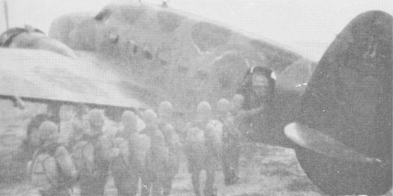
Near the end of 1941 one Ki-59 was modified into a glider with the removal of the engines and the landing gear replaced by under-fuselage skids. It was designated the Ku-8-I or Army Experimental Glider. This was further developed as the Ku-8-II or Army Type 4 Large Transport Glider which became the only operationally-used Japanese assault glider. It was named ‘Goose’ by the Allies but subsequently changed to ‘Gander’.
Carrying a crew of two and 15-20 armed troops, the Ku-8 jettisoned its main undercarriage after take-off, landing on fixed under-fuselage skids. The tail wheel was also fixed. Small vehicles or artillery pieces, when carried, were loaded from the front, the whole nose section hinging to starboard. Troop entry was via the outward opening door in the fuselage side.
Variants:
Ku-8-I (Army Experimental Glider) Experimental conversion to glider configuration.
Ku-8-II (Army Type 4 Large Transport Glider) (“Gander”) Assault-glider variant.
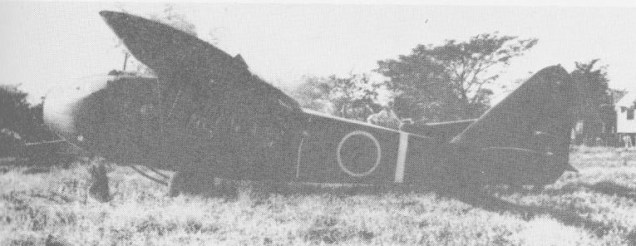
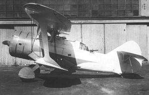
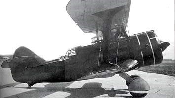
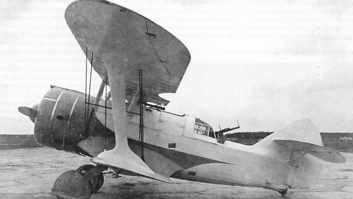
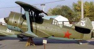
The DI-6 fighter (originally TsKB-11 (Russian: Кочеригин, Яценко ДИ-6)) was a development in 1934 by Kochierigin at the “ Aviorabotnik ” factory. The construction of the DI-6 was commissioned to the aeronautical engineer VP Yatsenko. The new fighter was projected in two main variants: two-seater fighter and attack aircraft. The DI-6 was the first fighter in the world to use a retractable landing gear with shock absorbers located on the main wheel discs.
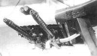
The fighter’s armament consisted of two 7.62-mm (0.30-in) ShKAS machine guns under the wings and another in a ring in the gunner’s cabin, all with 750 rounds. In the attack version, the gunner’s 7.62-mm (0.30-in) ShKAS machine gun was maintained and four PV-1s were added with a total of 3,000 shots (which could reach 4,000 when the plane was overloaded). In the attack aircraft version, in addition to the four underwing mounts, a weapons bay was provided in the fuselage capable of carrying four 10 kg aviation bombs and the ability to locate two VAP chemical weapons containers under the wings. Underwing racks carried four 12-kg (26-lb) bombs.
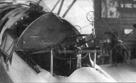
ShKAS machine gun in the gunner’s position.
The selected powerplant was the Yakovlev M-32 water-cooled V-engine, rated at 600 hp at 5000 meters. Six engines of this type had been produced on an experimental basis between 1932 and 1934, with a total of 1,200 hours of work on test benches, presenting so many difficulties that further development was cancelled. This led to major modifications to the fighter’s plans and mockup, to accommodate a 625-hp Wright Cyclone R-1820F-3 engine.
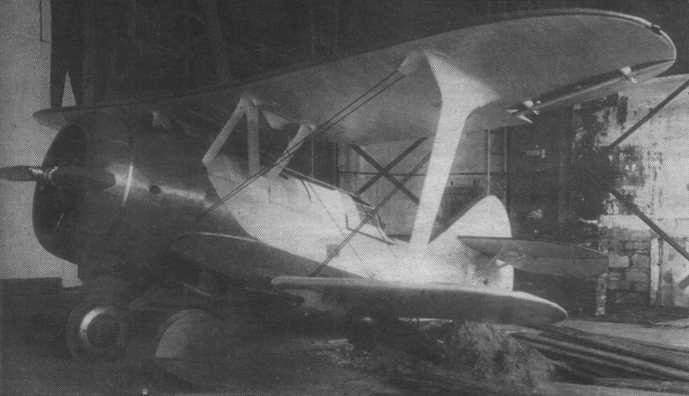
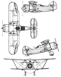
The wing structure was made up of two midplanes (upper and lower) and two pairs of wings joined by X-shaped studs. Both the upper and lower wings had a double spar structure made of wood with a fabric covering. The upper flange was built to the Clarke UN profile with a relative thickness of 10%. The ailerons with a duralumin structure and textile covering were located only on the upper wing. Two 76-liter fuel tanks were located in the center of the upper wing, which were characterized by their tendency to leak due to the poor quality of their finish. The thickness of the upper centerplane tended to decrease towards its center, being fixed to the fuselage by means of two N-shaped uprights made of chrome-molybdenum tubes.
The fuselage was built of chrome-molybdenum tubes. The fuselage frame was welded to the engine base and lower centerplane. The front cover was made of aluminum sheets. In the back, the covering was made of fabric. The tail was monoplane and of the conventional type. Both the rudder and the elevator were made of duralumin and covered with fabric. The empennage was built in its lower metal part, in the area where the stabilizers were fixed. The upper part featured a duralumin structure and a fabric covering.
The retractable landing gear featured 750х125mm main wheels with brakes and an internal hydropneumatic damping system. The retraction was carried out by means of a pneumatic system with compressed air and there was a mechanical system for emergencies. The tail skid was fixed and had hydro-pneumatic shock absorption.
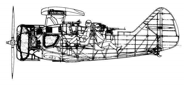
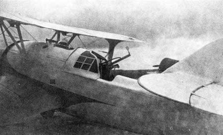
The cockpit was of the open type with a tempered glass windshield. The pilot’s seat was adjustable to accommodate his height. To improve the pilot’s field of vision to the rear, the gunner’s cabin was located at a lower level. This cabin was closed on three sides with transparent celluloid panels and featured glass windows on each side. The shooter had two seats: the main one, facing away from the pilot and used to operate the ShKAS machine gun, and an additional one that folded towards the right wall of the fuselage. The gunner’s cabin windshield was made up of two panels that had to be released in case of emergencies to allow the gunner to leave the aircraft.
In September 1934 the first experimental prototype TsKB-11, with its wings painted red, was delivered to the NII VVS for state testing. IF Petrov was appointed as main test pilot and Vinogradov as gunner. For Factory No. 39, test pilot Yu participated in the tests. I. Piontkovsky and the head of the experimental flight station N. Nikolayev. The first flight was carried out by the NII VVS AI Fili on September 30 and the second flight was only possible in December. During this time, the plane’s engine was replaced, the angle of the stabilizers was modified, and the landing gear retraction system was improved.
The retractable landing gear added some difficulties to the tests due to the lack of experience of the pilots with its handling. Thus, for example, on December 10, during a test flight, the main units could not be retracted due to an error by pilot Petrov in the sequence of the procedure. The following day, during the landing due to another problem, the plane was forced to land on its belly, resulting in slight damage. As a curious fact, the NII VVS sent an information to the Commissioner of heavy industry Sergo Ordzhonikidze, blaming the pilot IF Petrov for the failures. Petrov was called to clarify the facts, of which he made a detailed exposition. Upon returning to the institute, he was informed that by order of the commissioner and in gratitude for his conduct, he was given a new GAZ-1 car.
In the test results report, it was pointed out that due to engine problems in some flight regimes, there was vibration in the wings, especially on the left. The wing entered into resonance with the engine. During the takeoff roll, there was a tendency to lift the tail and the aircraft pulled to the left, which complicated takeoff during takeoff from unprepared aerodromes. The use of the reserve system for the extension of the landing gear demanded a lot of physical strength from the pilot. The lack of effectiveness of the ailerons made the plane tend to turn in flight. Another deficiency detected was that the pilot with his winter coat and parachute was unable to board or leave the device without help in an emergency. The gunner lacked communication with the pilot, which almost made it impossible at high altitudes or when the engine worked at high revolutions. Poor visibility from the cabin downwards and poor firing angle from the rear cabin were highlighted. In an emergency, the gunner did not find it any better than the pilot to leave the aircraft due to the narrowness of the access hatch and the need for great physical force to open the cover.
However, the conclusions were generally positive. The speed, the manoeuvrability and the absence of major defects, made it possible to suppose that the indicated problems could be solved in a short time, highlighting the great interest of the air forces in having an aircraft of its type. The report also pointed out the need to force the development of a second prototype with weapons and deliver it for testing, as well as prepare the conditions to build a small series. Factory No. 39 was asked, in parallel, to develop a single-seat escort fighter variant.
In relation to the landing gear and the wheels with internal cushioning, the report considered that the tests passed. Both the retraction and wheel scheme were recommended as a successful product. The NII VVS received the modified TsKB-11 in May 1935. On this occasion the testers of the aircraft were P. Ya. Fedrovi and VA Stiepanchonok. The tests culminated in November with results considered positive. Weapons were included in these tests, which also received a positive assessment. During these tests the pilots developed the tactical methods of using the new machine. In the surviving reports of the NII VVS several pages can be seen with schemes of variants to attack air targets and manoeuvres to defend against enemy attacks.
Among the deficiencies noted was again the lack of gunner firing angles that allowed the enemy aircraft to easily destroy its tail from the 6 o’clock position. The gunner’s position was awkward, adding to the fatigue. To retract the landing gear the pilot needed to perform 9 operations. Both the wings and the tail began to vibrate when the plane dived. There was a lack of communication between the pilot and the gunner and the difficulties faced by the latter in the event of having to abandon the aircraft in an emergency.
The conclusions of the NII VVS were presented to the head of the VVS RKKA Yákov I. Álksnis, who asked the head of the GUAP to order Factory No.39 in the shortest possible time to prepare one of the ten pre-series copies, which were already beginning to be released. assemble as DI-6M-25, for field tests with the elimination of all detected problems and the installation of an RI ZIET radio station.
In order to assess the ground attack capabilities of fighters, the USSR aeronautical development plans for 1934 called for the development of the following attack aircraft models: LSh-1 – Based on the Polikarpov I-16M-22; LSh-2 – Based on the Kochierigin/Yatsenko DI-6 (Russian: Кочеригин, Яценко ДИ-6Ш); LSh-4 – Based on the Sukhoi I-4 and Polikarpov I-5 fighters; LSh-5 – On the basis of the I-9, I-10 and I-11 fighter projects
The Kochierigin/Yatsenko DI-6Sh was also known as TsKB-38 because the prototype was developed at the Central Construction Bureau factory. Ground attack aircraft of 1935 developed on the basis of the DI-6 fighter by VP Yatsenko in the collective led by SA Kochierigin.
Kochierigin DI-6Sh
As a result of these plans, the TsKB-38 (DI-6Sh) two-seat fast attack aircraft was conceived, obtained from modifications to the DI-6 biplane fighter developed by Kochierigin.
On August 4, 1935, the S-96 request from the Labor and Defense Committee (STO) was received, which established the modification of the DI-6 as an attack aircraft with a maximum speed between 340 and 350 km/h at sea level and 390 -400 km/h at 3000 m, a landing speed between 90 and 95 km/h, radius of action of 400 – 500 km. Armament was to include six 7.62mm machine guns for attack, one machine gun for rear hemisphere defense, plus a bomb capacity of 80kg. According to this document, GUAP, through Factory No.39, had to develop the prototype in a period of 45 days, allowing it to be delivered without armament, in order to assess its installation once the tests were carried out. The GUAP was also requested industrial preparation for production at Factory No. 81 of the Di-6Sh from [1936].
The DI-6Sh was a development of the DI-6 and kept the same structure. Unlike the fighter version, armored protection was added to the pilot’s back and head and the configuration of the armament was modified, which came to consist of two PV-1 synchronized machine guns firing through the propeller, another four PV-1located under the lower wing at an angle of 12º7” towards the central axis of the aircraft and with 3,000 projectiles (4,000 in the overloaded version). There was also a weapons bay located under the pilot’s seat with a capacity for 40 kg of 8-10 kg bombs and the possibility of placing another 4 under the wings for a total of 80 kg. Two VAP-6 containers for chemical weapons could also be located on the underwing mounts.
Location of the PV-1 machine guns under the wing of the DI-6Sh
Defensive armament consisted of a 7.62mm ShKAS machine gun in the gunner’s position with 750 rounds.
With a flight weight of 2,115 kg, the DI-6Sh developed a speed of 305 km/h at sea level and 358 km/h at 3,000 meters. Climb time to 5,000 meters was 17.5 minutes.
DI-6Sh with VAP-6 pods under the wings
Between October 31 and November 19, 1935, the factory and range tests of the first example DI-6ShM-25 developed at the TsKB of Factory No.39, in the department directed by VP Yatsenko, were carried out.
The tests included only 10 flights. In eight of them the machine guns were tested and they worked without problems and in three bombardments with AO-8 aviation bombs were carried out and in two the spraying of chemical weapons from VAP-6 underwing containers was tested. The underwing machine guns worked properly. A range was prepared with wooden targets simulating soldiers and cavalry. Shooting in low flight, 80% of the models were hit, with more than 20% of the impacts concentrated in the groups of callery. The test was considered positive, noting that at flight heights greater than 17 meters, the pilot’s visibility towards the target decreases considerably. The tests of chemical weapons and the launching of bombs were also positive from the point of view of the work of the equipment.VVS, Yákov I. Álksnis, who decided to develop further armament tests of the DI-6Sh model with the participation of experienced pilots brought from operational units.
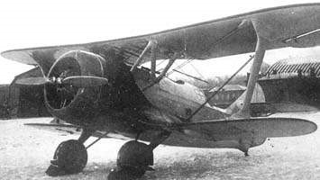
DI-6Sh attack aircraft
The tests showed that the model was not ready to act as an attack aircraft, not because of problems with the plane, but due to the inability of its configuration. During an approach flight to the target, the pilot’s attention was focused on controlling the aircraft and the gunner, on the other hand, he could not help at all due to his position, with his back turned. The pilot lacked the possibility of orienting himself using a map to reach the objective. The bomb load, located under the pilot’s cabin, meant an additional task for him and was ineffective because the pilot was unable to take aim as the target was covered by the body of the plane. All these reasons led to the loss of the main characteristic of an attack aircraft: the concentration on the ground objective. On the other hand, the range of the model, the number of bombs and their weight made the model useless as an attack aircraft. The long takeoff and landing run made it difficult to operate from battlefields.
DI-6Sh at the NII VVS
On the other hand, the pilots complained that the quantity and caliber of the bombs did not meet the operational needs of the plane. Controlling the aircraft in low-altitude flight became difficult because the aircraft began to vibrate and it was necessary to exert great force on the joystick.
Despite the difficulties, the DI-6Sh was accepted for series production and 61 examples were produced at Factory No. 1 from the end of 1936.
In the summer of 1938, dive bombing regimes with angles between 40 and 90º were tested on the DI-6Sh. As a result of the tests, the recommendations for this type of action were created, establishing a height at the beginning of the dive of no less than 2,500 meters. The dives showed that the aircraft could react to them favorably and the tail vibrations that characterized the model did not occur during the descent.
The deficiencies of the model as an attack aircraft made the decision to use it for training missions for the first stage of preparing the pilots for bombing and diving tasks. The lack of capacity to load bombs and the low caliber made its use as an attack aircraft in combat conditions impractical. For this reason, most of the DI-6Sh ended up in bombing training units.
Despite the country’s efforts, the attack aircraft of the Red Army arrived at the end of the 30s in a state of crisis. Although 12 attack regiments were registered by this time, the inspection carried out in the attack units in the first half of 1938 showed that the level of operation was really low. The diversity of models and the lack of technical availability characterized the attack structures. Of the 561 aircraft of this type there were 200 Polikarpov R-5 units, 62 Polikarpov R-5Sh units, 174 Polikarpov R-5SSS units, 60 Kocherigin/Yatsenko DI-6Sh units, 31 Tupolev R-6 units and 14 Tupolev SB.
DI-6 gunner’s position
Along with the DI-6Sh, Factory No. 39 delivered in February 1936 two pre-series DI-6M-25 (also sometimes named DI-6I highlighting its use as a fighter) for the development of tests under conditions of Campaign. These tests were led by the NII VVS airfield commander, Major Spirin and included in the brigade were weapons engineer Ssorin and test pilot AI Nikashin. The first tests of the DI-6 were carried out in February with skis undercarriage. The tests of the two prototypes were carried out until April 10, when the snow began to melt and flights were no longer possible. These two with wheels participated in the festivities for May Day. At the end of May, at the NII VVS aerodrome, a third prototype joined the tests.
Field tests ended in June 1936. Mock combat between DI-6 and Polikarpov I-15, I-16 and R-5 reconnaissance aircraft took place. With respect to the R-5, the DI-6 was superior both in vertical and horizontal maneuvers. With respect to the fighters, the advantage of the DI-6 appeared during maneuvers through the vertical.
In June 1936 the first series DI-6 arrived at the NII VVS. Engineer AI Nikashin and test pilot E. Yu. Prieman made 33 flights on it over 28 days. After two years of development, it was not possible to significantly improve its performance. The addition of equipment and improvements based on test data brought about an 81 kg increase in weight. The maximum speed decreased by 16 km/h and the takeoff run had increased by 70%. Tail vibration when entering steep dives could not be fixed. The gunner’s firing angles still did not satisfy the VVS. The main problem was that they were practically the same as those that had been reported since the first tests in the NII VVS. It has been commented that many of the unresolved problems were due to Yatsenko’s difficult nature, which several of his colleagues branded as stubborn and as a person who did not like to give up. However, the DI-6 had already been approved for serial production, so Yákov I. Álksnis was forced to request GUAP to correct all the defects indicated in the aircraft that were already being produced at Factory No.81 as a condition to receive them at the VVS.
In 1937 the series DI-6 began to arrive in units. Meanwhile at the NII VVS work continued to try to improve the airplane. For the month of June, the series DI-6M-25s produced at Factory No.81 began to arrive. These copies had even bigger problems, including some already corrected during development.
DI-6 as standard in the yard of Factory 81
In the fall of 1937 test pilot Nikashin began testing a further improvement of the DI-6M-25 built at Factory No. 81. It differed by presenting an “Eklips” (“Эклипс”) electrical system for starting the engine, made up of an accumulator and a DFS-500 (ДФС-500) generator; a radio system SPU-2 (СПУ-2); improved fuel system with welded tanks; oil cooler of new type and new wheels on the landing gear. The fixing of the protective panels in the gunner’s cabin was modified. In emergencies both panels would come loose. The engine hood was also improved and a new 2.8 meter diameter propeller was added. Another important improvement was introduced in the firing angle of the gunner. All this new equipment increased the weight of the device to 2033 kg, which meant an increase of 159 kg with respect to the TsKB-11, and 80 kg in relation to the first series aircraft of Factory No. 81.
In December 1937 the test pilot Nikashin and his assistant Sokolov completed the state tests of the improved version DI-6M-25B (No. 81024), which differed mainly in the new M-25B engine.of 775 hp, the location of the tailplanes in a lower position, the increase in the area of the ailerons by 0.25 sq.m, the addition of an audible signal for landing gear deployment and retraction. Control of the wheel brakes was transferred to the joystick. The wing machine gun feed system was modified from a Factory No. 81 proposal. The tail modifications significantly decreased vibrations and the tendency to lift the tail on takeoff. Brakes on the lever turned out to be more comfortable than on the pedals. Despite the increase in weight coupled with these modifications, the sec benefits were quite close to those of the first prototype. Despite being slightly inferior in manoeuvrability, the DI-6M-25Bit featured the same horizontal speed as the Polikarpov I-15bis.
In January 1938 the latest version of the DI-6 was tested, the DI-6bis (Airplane “21”). This model was powered by an M-62 engine with a variable pitch propeller. When the prototype was finished at Factory No. 81, the engine was not yet ready, so an M-25B with a constant-pitch propeller and 2.8 m diameter was installed. Unlike previous models the DI-6bis featured fixed landing gear, a single cover oved the pilot and gunner cabins, the controversial tank located in the upper center plane was eliminated and the capacity of the wing tanks was increased, the machine guns were located on the wing and the boxes with the ammunition under the bottom plane. The support of the gunner’s weapon, the brake system (which returned to pedal control) was also modified. The lower wing was fitted with flaps.
During the tests, a decrease in the maximum speed at sea level of 16 km/h and at 3000 meters of 29 km/h was verified. Rate of climb and manoeuvrability were practically unchanged. A set of characteristics if considerably improved: improved take-off, the tendency to turn to the left during the take-off roll disappeared. Landing with the flaps became more complex. The angle of fire of the gunner was improved, which featured a new KTP-5 sight. In the conclusions of the tests it was reflected that the “21” Aircraft, even with the M-62 engine, was not in a condition to compete with the new two-seater fighters, therefore its use as a trainer or scouting aircraft was recommended. Factory No. 81 was requested to make changes to the second cockpit to adapt the aircraft to these new roles. The second prototype with these changes was never completed due to lack of supply of the M-62 engine. In total, 222 examples were built.
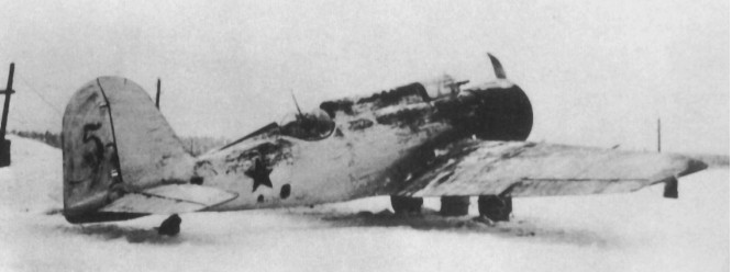
The first three series examples tested in the NII VVS, together with seven others, were framed from October 1936 in the 56th fighter brigade of the Kiev district.
DI-6 as standard in an operating unit
The operational career of the DI-6 was not very long. In the second half of 1939 it began to be withdrawn from fighter units, being replaced by the Polikarpov I-15bis. In that year the few copies that remained in operation in the units of the Kiev district were assigned to reconnaissance tasks in two squadrons. Most of the other examples in service were used solely as attack aircraft, but with a capacity of only 40 kg, even in this role it could not be considered effective. In the fall of 1939 the 56th Assault Regiment of the 52nd Aviation Brigade from Omsk, in the Siberian District, which maintained 63 DI-6Sh aircraft (of which 8 were out of service) began to operate the Tupolev SB bomber.
Of the 173 DI-6 planes that were in service on January 1, 1940, it was planned to maintain 39 planes in two squadrons, deliver 99 to training centers and withdraw 35. The copies used in the training center were generally used as study material. No evidence of its use in flight has been found. Claims that DI-6 fighters participated in the Battle of Jaljim Gol or the Finnish War are considered unfounded.
Despite the myriad of problems described along these lines, it’s not fair to characterize the DI-6 as a bad plane. During all the time it was operated, there was never a catastrophe and due to the number of problems reported and small breaks, it did not stand out as a leader in its time either.
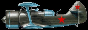
A replica of the DI-6 is displayed at the Museum of the Great Patriotic War in Moscow.
Replica of the Kochierigin DI-6
TsKB-11 Initial designation of the prototype.
DI-6M-25 Main production version as a fighter. Engine: 1 x 700 hp Shvietsov М-25 Upper wingspan: 9.94 m Lower wingspan: 7.43 m Wing area: 25.16 m² Length: 6.87m Height: 3.20m Empty weight: 1360 kg Loaded weight: 1,955 kg Normal takeoff weight: 2033 m Wing loading: 78 kg/m² Maximum speed at sea level: 324 km/h Maximum speed at altitude: 372 km/h Cruising speed: 313 km/h ROC: 611 m/min Time to 5000 m: 10 minutes Practical range: 550 km Practical ceiling: 7700 m Armament: Three 7.62mm ShKAS machine guns / 750 rounds each. Bomb load: 40 kg Accommodation: 2
DI-6M-25B Improved version of 1937, lowered tailplanes, increased wing area. Engine: 775 hp M-25B
DI-6Sh (TsKB-11Sh, TsKB-38) Attack version with four PV-1 machine guns located under the wings. Engine: 1 x 700 hp Schvietsov М-25 Upper wingspan: 9.94 m Lower wingspan: 7.43 m Wing área: 25.16 m² Length: 6.87m Height: 3.20m Empty weight: 1434 kg Loaded weight: 2155 kg Normal take-off weight: 2033 m Wing loading : 78 kg/m² Maximum speed at altitude: 358 km/h Cruising speed: 312 km/h ROC: 611 m/min Time to 5000 m: 10 minutes Practical range: 500 km Practical ceiling: 7200 m Accommodation: 2 crew members (pilot and gunner) Armament: 7 x PV-1 machine guns Bombload: 80 kg
DI-6bis (Aircraft “21”) Fixed landing gear. Designed for M-62 engine, tested with the M-25B. Just a prototype.
DI-6MMSh A prototype with an M-300 engine. Its acronym stands for Small Attacker Modification (малая модификация штурмовика). It was not produced.
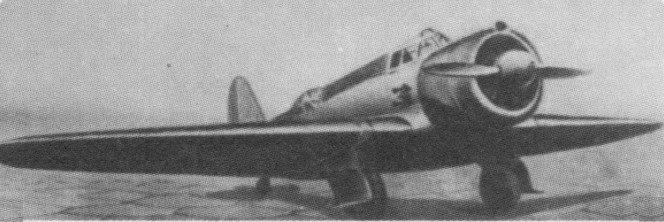
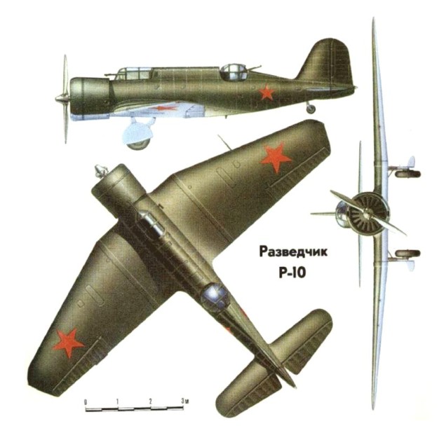
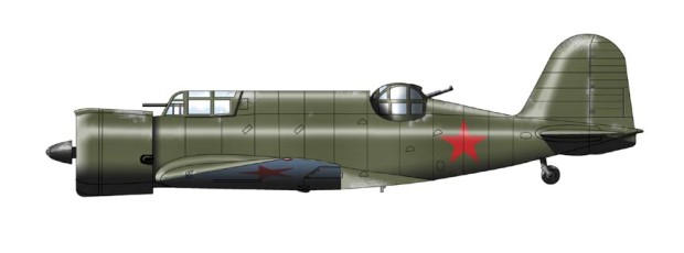
KhAI-5 was a prototype of the fast photoreconnaissance aircraft. It featured numerous innovations developed for KhAI-1 aircraft, including retractable gear, wing and control surfaces with stressed skin, internal bomb/camera bay, new type of gunner’s turret, and remotely controlled camera capable to make shots at 80° relatively to flight direction. Neman’s slogan was “No parts in the air flow”, so the whole design was very clean.
The KhAI-5 had low, plywood-covered wooden wings. The fuselage was of semi-monocoque construction. The undercarriage retracted into the wings. The crew consisted of two: a pilot and an observer-rear gunner in separate compartments; the observer sat in a turret with one machine gun. In the observer compartment’s floor there was an AFA-13 camera for reconnaissance duties. Between the crew compartments there were fuel tanks and a vertical bomb bay. The maximum bomb load was 300 kg/661 lb (6 × 50 kg/110 lb or 10 × 25 kg/55 lb). The plane was powered initially by the M-25A, later M-25V radial engine power: 540 kW (730 hp). The two-blade propeller was made of metal. Armament consisted of 2 x fixed forward firing 7.62 mm (0.300 in) ShKAS machine-guns in the forward top decking and 1 x manually aimed ShKAS machine-gun in the rear turret.
The first prototype of the plane, with a factory designation KhAI-5 (ХАИ-5), flew in June 1936. Despite a lower performance, the aircraft won a contest against another reconnaissance plane design, the Kotcherigin R-9, and was accepted for a production with the military designation R-10 (‘R’ for razvyedchik – reconnaissance). 493 R-10s had been manufactured in Kharkiv and Saratov aviation plants by early 1940. The first series showed some teething problems, and because of these I. Neman was arrested by the NKVD on December 11, 1938 under false accusation of sabotage and espionage.
In 1938, a variant KhAI-5bis was tested – fitted with an M-25E engine, it developed a speed of 425 km/h (264 mph). In 1938, the KhAI-52 ground attack aircraft, based on the R-10, was also developed. It was fitted with an M-63 670 kW (900 hp) engine and armed with seven machine guns and 400 kg (882 lb) bombs. A production run of an experimental series of 10 aircraft was prepared, but it was cancelled after one was produced and I. Neman had been arrested.
In total over 490 were built.
Some production R-10s were fitted with more powerful Tumansky M-88, Shvetsov M-62 and M-63 engines. Over 60 aircraft, withdrawn from the Air Force, were used from 1940 as mail carriers by Aeroflot, under the designation PS-5 (Russian: ПС-5), with 3 passenger seats.
The aircraft entered service in the Soviet Air Force in 1937, replacing some Polikarpov R-5s. R-10s were first used in combat in the Soviet-Japanese Battle of Khalkhin Gol in 1939. Then, they were used in the initial stage of the World War II, starting with use against Poland in the Invasion of Poland (without combat encounters) and against Finland in the Winter War (1939–1940). R-10s were next used in the first period of the German-Soviet war, following the German attack on June 22, 1941. By this time, they were outdated and suffered heavy losses. They were used as close reconnaissance aircraft, and, in need, also as light attack bombers. Later many were used as night bombers, to avoid losses in encounters with fighters. The remaining R-10s were withdrawn from combat service in 1943 (two Finnish pilots claimed shooting R-10 in 1944).
Variants R-10 – Production version of KhAI-5 KhAI-5bis / KhAI-51 – Improved R-10/KhAI-5, one example flown early 1939. KhAI-52 – Production version of KhAI-51. Ten ordered but production halted with the arrest of I.Nyeman.
Specifications Engine: 1 × Shvetsov M-25V, 531 kW (712 hp) Propellers: 2-bladed Hamilton Standard two-pitch propeller Length: 9.3 m (30 ft 6 in) Wingspan: 12.2 m (40 ft 0 in) Wing area: 26.8 sq.m (288 sq ft) Empty weight: 1,823 kg (4,019 lb) Gross weight: 2,515 kg (5,545 lb) Fuel capacity: 260 kg (573 lb) fuel + 30 kg (66 lb) oil Maximum speed: 350 km/h (217 mph; 189 kn) at sea level, 388 km/h (241 mph) at 2,500 m (8,202 ft) Landing speed: 125 km/h (78 mph) Range: 1,450 km (901 mi; 783 nmi) Service ceiling: 7,700 m (25,262 ft) Time to altitude: 1,000 m (3,281 ft) in 2 min 24 sec, 5,000 m (16,404 ft) in 12 min Take-off distance: 250 m (820 ft) Landing distance: 230 m (755 ft) Crew: 2 Armament: 2 x fixed forward firing 7.62 mm (0.300 in) ShKAS machine-guns in the forward top decking 1 x manually aimed ShKAS machine-gun in the rear turret Bombload: 6 x 50 kg (110 lb) FAB 50 bombs in internal bays
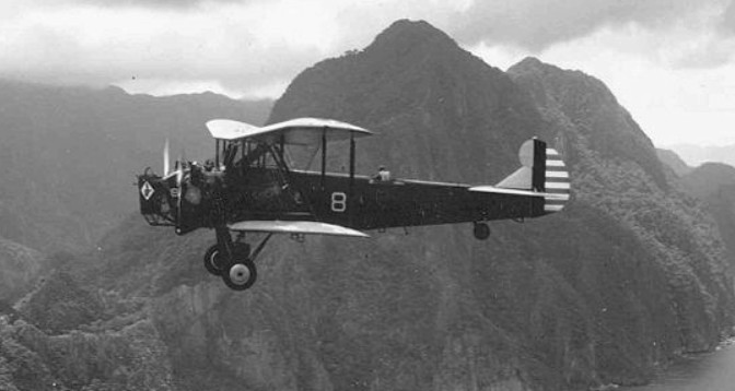
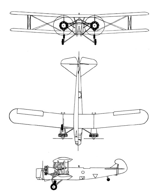
Developed from the Keystone B-3, the Keystone B-4 was a biplane bomber produced for the United States Army Air Corps in 1930. Originally seven were ordered by the United States Army Air Corps as the LB-13 light bomber. They were to be equipped with single vertical tails and were to be powered by a pair of 525 hp Pratt & Whitney GR-1690 radials. Serials were 30-344/353. When the LB- designation was dropped in 1930, the first five planes were redesignated Y1B-4. (The Y1B- designation indicates that funds for the design did not come from the normal annual funds.) Of seven LB-13s ordered, five were completed as Y1B-4s with 575 hp R-1860-7 engines (30-344/348). The Y1B-4 had a slightly better performance than the B-3A because of the more powerful engines, but was otherwise almost exactly the same.
The first B-3A (S/N 30-281) was converted to Y1B-4 configuration with the addition of R-1860-7 radial engines and low pressure tires. Because of more powerful engines, the performance of the Y1B-4 was a slight improvement on the B-3, but the only difference between the two planes was their engines.
On April 28, 1931, the army ordered 25 improved Y1B-4s as the Keystone B-4A. Serials were 32-117/141. This production version was part of the last biplane bomber order made by the Army Air Corps (along with 39 B-6As, identical in all respects except their make of engine), and the B-4As, delivered between January and April 1932, were the last biplane bombers delivered to the Air Corps.
Like the B-3A, the B-4A carried five crew members; two pilots, a bombardier, and a front and rear gunner. The B-4A was externally almost identical to the B-3A which preceded it (as well as to the B-5 and B-6 which followed it).
B-4 was the last of the Keystone biplane bombers ordered by the U.S. Army in late 1931. These aircraft were used primarily as observation and reconnaissance aircraft as early as 1934 when the Martin B-10B went into operational service. Some remained in service into the early 1940s.
In 1932, Keystone produced 25 B 4As (575 hp R 1860 7 Hornets) and 39 B 6As (575 hp R 1820 1 Cyclones). Like the B 3A, these also had single tails; their armament was reduced to three 0.30 in (7.62 mm) guns, and bombload increased to 1130 kg (2500 lb).
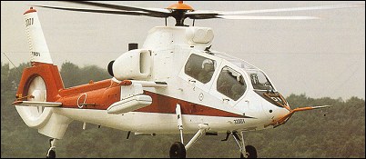
Developed to replace OH-6Ds of JGSDF, the Japan Defence Agency (IDA) awarded Y2.7 billion (US$22.5 million) in FY92 to cover the basic design phase of the helicopter then provisionally designated OH-X. Requests for proposals were issued by JDA’s Technical Research & Development Institute (TRDI) 17 April 1992 and Kawasaki was selected as the prime contractor (60% of programme) on 18 September 1992, with Fuji and Mitsubishi (20% each) as partners. The Observation Helicopter Engineering Team (OHCET) was formed by these three companies, beginning with a preliminary design phase 1 October 1992. A mockup was made public on 2 September 1994 under the Japanese name Kogata Kansoku (new small observation [helicopter]). The programme included six prototypes (four flying, two for ground test), and the first aircraft (32001) rolled out at Gifu on 15 March 1996 and made first flight 6 August 1996, followed by second prototype on 12 November. The OH-1 designation was assigned late 1996. The first two XOH-ls were handed over to JDA on 26 May and 6 June 1997. The third flown on 9 January 1997, at which time the earlier aircraft had accumulated some 30 and 20 hours, respectively. The third was handed over on 24 June 1997. The fourth was flown on 12 February 1997 and handed over 29 August 1997. The prototypes were renumbered by 1999 from 32001-04 to 32601-04. The Japan Defence Agency’s Technical Research and Development Institute was looking to develop an attack version of the Kawasaki OH 1 armed reconnaissance helicopter which in 1998 was at the flying prototype stage. Consideration was being given to replacing the OH 1’s single Mitsubishi XTS1 10 engine with two LHTEC T800 or MTU/Turbomeca&Rolls-Royce MTR 390 turboshafts for the AH 2, together with a new gearbox and rotor system, plus a new integrated sensor targeting and weapon system. The first three production OH-1s were funded FY97 and ordered in 1998. The first prototype was flown with more fuel-efficient TS1-10QT (replacing XTS1-10) engines, on 30 March 1998. By early 1999, four prototypes had flown 450 hours and were due to complete further 450 hours by end of 1999, including operational evaluation at Akeno JGSDF base. The first production OH-1 (32605) flown July 1999 and handed over to JGSDF at Gifu 24 January 2000. Name ‘Ninja’ reportedly given in 2002, but not officially confirmed.
The OH-1 features Kawasaki hingeless, bearingless and 20mm ballistic-tolerant four-blade elastomeric main rotor and transmission system; Fenestron-type tail rotor with eight unevenly angled ‘scissor’ blades (35 and 55 degrees); stub-wings for stores carriage. Active vibration damping system. Flying controls are integrated AFCS and stability control augmentation system (SCAS). The rotor blades and hub are manufactured from GFRP composites; centre-fuselage and engines by Mitsubishi, tail unit/canopy/stub-wings/cowling by Fuji, rest by Kawasaki. Some 37% of airframe (by weight) in GFRP/CFRP. The landing gear is a non-retractable tailwheel type, with provision for wheel/skis on the main units. Power is from twin 662kW FADEC-equipped Mitsubishi TS1-10QT turboshafts (XTS1-10 originally in prototypes), and the transmission has a 30-rninute run-dry capability. Stub-wings can each carry a 235 litre auxiliary fuel tank. The crew of two are on tandem armoured seats (pilot in front) with flat-plate cockpit transparencies, upward-opening on the starboard side for crew access. Armament is four Toshiba Type 91 (modified) lightweight short-range, IR-guided AAMs on pylons under stub-wings for self-defence.
Funding for development, prototypes and flight testing Y2.5 billion in FY92, Y10.2 billion in FY93, Y50.1 billion in bY94 and Y23.3 billion in FY95. Unit costs of first four production lots Y1.924 billion (FY97), Y2.018 billion (FY9S), Y2.229 billion (FY99) and Y2.075 billion (FY00).
The Hiko Jikkentai (Flight Test Squadron) was formed at Akeno with first four production aircraft on 27 March 2001; other deliveries by late 2002 included small numbers to Kasumigaura Bunko, Utsunomiya Bunko and Kyoiku Shien Hikotai (at Akeno), all of which are departments of the Army’s Koku Gako (Aviation School). A total of 20, including prototypes, were ordered by FY02, and at least 12 delivered by late 2002.
OH-1 Engines: 2 x Mitsubishi TS1-10 Main rotor diameter: 11.6m Fuselage length: 12.0m Height to top of rotor head: 3.4m Height over tailfin: 3.8m Empty weight: 2450kg Normal take-off weight: 3550kg Max take-off weight: 4000kg Max level speed: 277km/h Combat radius: 200km Range: 550km
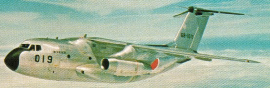
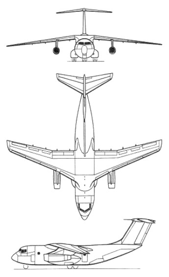
Designed to replace the JASDF’s Curtiss C 46 Commando transport aircraft, the Kawasaki C 1 first flew on 12 November 1970 and was delivered from December 1974.
Power is provided by two 14,500 lb thrust Mitsubishi produced Pratt & Whitney JT8 M 9 turbofan engines and it can carry 60 troops, 45 paratroops, 36 stretchers, or 26,235 lb (11,900 kg) of freight (including vehicles).
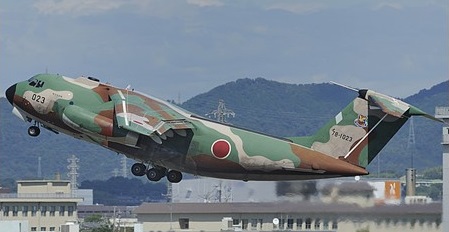
Inordinately expensive because of Japan’s relative inexperience in creating this type of airplane, by law the C 1 could not be sold abroad. Production ceased after 31 were built for the Japanese military, by a consortium of companies including Mitsubishi Heavy Industries, Kawasaki Heavy Indus¬tries, Fuji Heavy Industries, Nihon, Shin Meiwa and Sumitomo Precision practically all the companies involved in Japanese aircraft production.
By 1981 the 31 production C-1s had been delivered, including several long-range aircraft with an additional 4,732 litre wing centre-section fuel tank.
Kawasaki has modified a single C-lA twin-jet tactical transport for use in the ECM training role. Serialled 78 1021, the aircraft was fitted with seven radomes. Featuring nose and tail radomes housing elements of the TRDI/Mitsubishi Electrics XJ/ALQ-5 ECM system, the C-1ECM completed trials with the JASDF’s Air Proving Wing in 1986, and is now in service with the Electronic Warfare Training Unit.
Variation: Science & Technology Agency Asuka
C-1 Engines: 2 x P+W JT80D-M-9A, 64.5kN Wingspan: 30.6 m / 100 ft 5 in Length: 29.0 m / 95 ft 2 in Height: 10.0 m / 32 ft 10 in Wing area: 120.5 sq.m / 1297.05 sq ft Max take-off weight: 38600 kg / 85099 lb Empty weight: 23700 kg / 52250 lb Max. speed: 815 km/h / 506 mph Cruise speed: 705 km/h / 438 mph Ceiling: 12200 m / 40050 ft Range w/max.fuel: 3300 km / 2051 miles Range w/max.payload: 1300 km / 808 miles Crew: 5 Passengers: 60
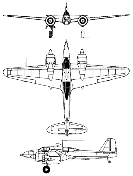
Derived from the Ki-96 twin-engine single-seat fighter, the Kawasaki Ki-102b was intended as a two-seat attack fighter. Some assemblies of the Ki-96 prototypes were incorporated into the three Ki-102 prototypes, the first completed in March 1944.
A cantilever mid-wing monoplane with a conventional tail unit, retractable tailwheel landing gear and two Mitsubishi Ha-112-11 radial engines, the Ki-102 carried a two-man crew in separate enclosed cockpits in tandem.
The prototypes were followed by the construction of 20 pre-production aircraft and in October 1944 the type was ordered into production.
Kawasaki modified six of the preproduction Ki-102s to serve as prototypes of a twin-engine high-altitude fighter for the Imperial Japanese Army. This differed from the attack fighter by having improved two-seat accommodation, a revised tail unit and Mitsubishi Ha-112-IIru engines with turbochargers. Successful testing of this version in mid-1944 resulted in a high-priority production order, but problems with the turbocharged engine resulted in only about 15 being delivered to the army before the war ended.
The design had also been revised to produce a night-fighter version under the designation Ki-102c, but only two examples were completed. These had increased wing span, a lengthened fuselage, redesigned tail surfaces, primitive AI radar, and armament of two 30mm Ho-105 cannon in the underfuselage and two 20mm Ho-5 cannon mounted obliquely in the fuselage to fire forward and upward.
Twenty Ki.102b were built with one 57mm and two 20mm cannon, one 12.7mm machine gun and provision for 1100 lb of bombs. Maximum range was 1243 miles and ceiling just over 36,000 ft.
Ki-102b aircraft, which were allocated the Allied codename ‘Randy’, saw comparatively little service, some being used in action over Okinawa, but the majority were held in reserve in Japan.
Ki-102b Engines: 2 x Mitsubishi Ha-112-II, 1125kW Wingspan: 15.57 m / 51 ft 1 in Length: 11.45 m / 37 ft 7 in Height: 3.7 m / 12 ft 2 in Wing area: 34 sq.m / 365.97 sq ft Max take-off weight: 7300 kg / 16094 lb Empty weight: 4950 kg / 10913 lb Max. speed: 580 km/h / 360 mph Ceiling: 13500 m / 44300 ft Range: 2000 km / 1243 miles Armament: 1 x 57mm cannon, 1 x 12.7mm machine-guns Crew: 2
The Japanese Army was faced with the prospect of having 270 Ki-61-II airframes sitting around waiting for installation of their Ha-140 liquid-cooled engines.
The Ha-140 engine had proven to be totally unreliable, and, to make matters worse, the Akashi factory manufacturing the Ha-140 had been destroyed in a B-29 raid. Since Japan desperately needed aircraft capable of intercepting the B-29, in November of 1944 the Ministry of Munitions instructed Kawasaki to install a different powerplant in the 275 Ki-61-II airframes gathering dust in the Kagamigahara factory in an attempt to get as many aircraft in the air as possible.
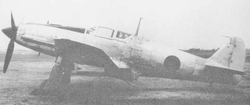
Kawasaki settled on the 1500 hp Mitsubishi Ha-112-II fourteen-cylinder double-row radial engine. This engine had established a standard of easy maintenance and reliable service, however, the Ha-112 was a radial engine, and, with a diameter of four feet, the installation of this engine in a fuselage only 33 inches wide provided a major challenge. The Kawasaki concern was guided in its work by being able to study the engine mount in an imported Focke-Wulf Fw 190A, an example in which a wide radial engine had been successfully installed in an airframe with a narrow width. In addition, the same Mitsubishi Ha-112 radial engine had been successfully installed in the Aichi-built D4Y3 (Allied code name JUDY) dive bomber, earlier versions of which had been powered by a liquid-cooled engine.
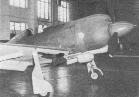
Kawasaki’s design team converted three airframes to serve as prototypes, installing a Mitsubishi Ha-112-II engine which had the same power output as the unreliable Ha-140. The new project was sufficiently different from the Ki-61 Hien that it was assigned a new Kitai number: Ki-100.
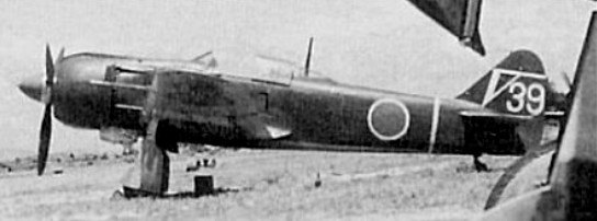
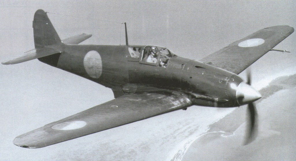
The first Ki-100 prototype aircraft made its first flight on February 1, 1945. The results of the flight testing exceeded everyone’s expectations. The Ki-100 was about 600 pounds lighter than its Ki-61-II predecessor. Maneuverability and handling were markedly improved due to the lower wing and power loading.
Although the maximum speed of the Ki-100 was slightly lower than that of the Ki-61-II because of the higher drag exerted by the radial engine, this performance could be reliably attained because of the better reliability of the Ha-112 engine. The design was ordered into immediate production as the Army Type 5 Fighter Model 1A (Ki-100-Ia). The first Type 5 fighters (Ki-100-Ia) were direct conversions of existing Ki-61-II airframes. 271 airframes were converted between March and May 1945, and were immediately delivered to operational units.
The Ki.100 also had provision for carrying two 550 lb bombs externally.
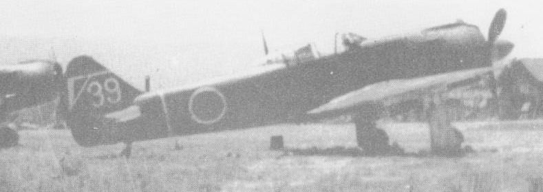
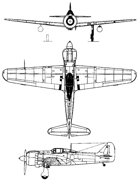
In combat, the Ki-100-Ia proved to be an excellent fighter, especially at low altitudes. It possessed a definite ascendancy over the Grumman F6F Hellcat. In one encounter over Okinawa, a Ki-100-equipped unit destroyed 14 F6F Hellcat fighters without loss to themselves. When the Ki-100 encountered the P-51D Mustang at low or medium altitudes over Japan, it was able to meet the American fighter on more or less equal terms. The outcome of P-51D vs Ki-100 battles was usually determined by piloting skill or by numerical advantage rather than by the relative merits of the two fighter types. However, at altitudes above 26,000 feet, the maneuverability of the Ki-100 began to fall off rather severely and the fighter was at a relative disadvantage in intercepting the high-flying B-29. With the Ki-100 proving such a success, it was decided to initiate production of this aircraft, the resulting Ki-100-Ib differing only by having the cutdown rear fuselage and all-round-view canopy that had been designed for the proposed Ki-61-III.
The first Ki-100-Ib fighters were built at the Kagamigahara and Ichinomiya Kawasaki factories in May of 1945, but production was severely hampered by the continual Allied bombing. Plans had been made to produce 200 fighters per month, but the Ichinomiya plant was forced to shut down in July 1945 after having built only 12 aircraft, and the Kagamigahara plant had its production severely curtailed by aerial attacks. By the time of the Japanese surrender, only 118 Ki-100-Ib aircraft had been delivered.
Ki.100-1b
In an attempt to improve the high-altitude performance, the Ki-100-II version was evolved. It was powered by a 1500 hp Mitsubishi Ha-112-II Ru with a turbosupercharger and water-methanol injection to boost power for short intervals. Because of a lack of space, the turbosupercharger had to be mounted underneath the engine without provision for an intercooler and its associated ducting, with air being ducted directly from the compressor to the carburetor. It first flew in May 1945. The lack of an intercooler limited the high-altitude performance of the Ki-100-II, and the turbosupercharger added 600 pounds to the weight, which reduced maximum speed by 15 mph at 10,000 feet. However, the boosted high-altitude power enabled a maximum speed of 367 mph to be be reached at 32,800 feet (the cruising altitude of the B-29 during daylight operations). It had been planned to begin production of the Ki-100-II in September of 1945, but only three prototypes of this high-altitude interceptor had been produced by the time of the Japanese surrender.
A total of 396 Ki-100s were built, including 275 Ki-61-II conversions, 118 Ki-100-Ib production aircraft built from scratch, and three Ki-100-II prototypes. Most of them were assigned to the defense of the home islands, operating from Chofu and Yokkaichi from the spring of 1945. At the end of the war, two Ki-100-Ibs were shipped to the USA for evaluation. The Ki-100 never had a separate Allied code name assigned to it.
Ki-100-I Engine: 1 x Mitsubishi Ha-112-II, 1125kW Max take-off weight: 3495 kg / 7705 lb Empty weight: 2525 kg / 5567 lb Wingspan: 12 m / 39 ft 4 in Length: 8.82 m / 28 ft 11 in Height: 3.75 m / 12 ft 4 in Wing area: 20 sq.m / 215.28 sq ft Max. speed: 580 km/h / 360 mph Cruise speed: 400 km/h / 249 mph Ceiling: 11000 m / 36100 ft Range w/max.fuel: 2200 km / 1367 miles Range w/max.payload: 1400 km / 870 miles Armament: 2 x 20mm cannons, 2 x 12.7mm machine-guns Crew: 1
Kawasaki Ki-100-Ia Army Type 5 Fighter Model 1a Engine: 1 x Mitsubishi [Ha-33] 62 or Ha-112-II, 1500 hp Takeoff, 1350 hp at 6560 ft, 1250 hp at 19,030 ft Wingspan: 34 ft 4 7/16 in Length: 28 feet 11 1/4 in Height: 12 feet 3 5/8 in Wing area: 215.3 sq.ft Empty weight: 5567 lb Loaded weight: 7705 pounds. Max speed: 360 mph at 19,685 ft / 332 mph at 32,810 ft. Time to 16,405 ft: 6 min. Service ceiling: 36,090 ft. Maximum range: 1367 miles. Armament: Two fuselage-mounted 20-mm Ho 5 cannon and two wing- mounted 12.7 mm machine guns.
Ki 100 1b Engine: 1,500 hp Mitsubishi Ha.112 11. Wing span: 39 ft 4.25 in (12m). Length: 28 ft 11.25 in (8.82 m). Height: 12 ft 3.75 in (3.75 m). Wing area, 215.278 sq.ft (20 sq.m). Empty wt: 5,567 lb (2 525 kg). Loaded wt: 7,705 lb (3 495 kg). Max speeds of 317 mph (510 kph) at 3,280 ft (1 000 m), 352 mph (567 kph) at 16,400 ft (5 000 m), 360 mph (580 kph) at 19,685 ft (6 000 m), and 332 mph (535 kph) at 32,800 ft (10000 m). Climb to 16,400 ft (5 000 m): in 6 min, 26,250 ft (8 000 m): 11.5 min, 32,800 ft (10 000 m): 20 min. Service ceiling: 36,090 ft (11000 m). Cruising speed: 248 mph (400 kph) at 13,123 ft (4 000 m). Armament: two 20 mm Ho.5 cannon and two 12.7¬mm Type 103 machine guns.
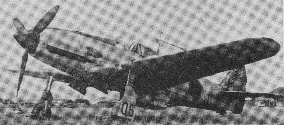
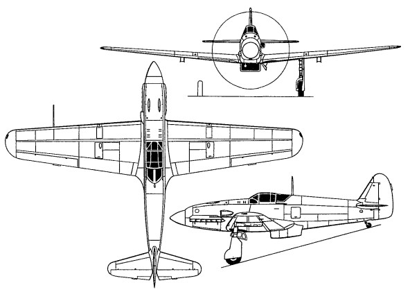
The Ki-61’s designers, Takeo Doi and Shin Owada, had worked under the German Richard Vogt, and in December 1940 they were instructed to go ahead with the Ki-61, and one year later the prototype was flown. Powered by an inverted V-12 inline engine, the Kawasaki Ha-40 being in effect a lightweight Daimler-Benz DB 601A built under licence.
The first of 12 Ki.61 prototypes was flown in December 1941 and went into production shortly afterwards.
The first production Ki-61-I fighters were deployed operationally in April 1943 when the 68th and 78th Sentais arrived in New Guinea. Named Hien (Swallow) in service (and codenamed ‘Tony’ by the Allies), the new aircraft proved popular with its pilots. Being well-armed and armoured, the type was a match for opposing American fighters. Its armament (of four 12.7-mm machine-guns) proved inadequate to knock down enemy bombers, and the Ki-61 I-hei(c) was introduced with a pair of Mauser MG151 20-mm cannon in the nose, these being replaced in a small number of Ki-61 I-tei(d) fighters by two Japanese built 30-mm cannon. The Ki-61-I and Ki-61-I KAI remained in production until 1945, but in 1944 they were joined in service by the Ki-61-II with more powerful Kawasaki Ha- 140 engine (producing 1500 hp / 1119-kW); with a top speed of 610km/h this would have been an excellent fighter but for constant engine problems; yet when fully serviceable the Ki-61-II was one of the few Japanese fighters fully able to combat the Boeing B-29 at its normal operating altitude, particularly when armed with four 20-mm cannon. The Ki-61-II featured a larger wing and modified cockpit canopy. Engine difficulties limited the number completed to eight.
A complete redisgn was undertaken for the Ki.61-IIKai, and 99 of these were built as Ki.61-IIa and –IIb.
The Ki-61-III project, featuring a cut-down rear fuselage with an all-round visin cockpit canopy, did not achieve production, being superseded by the Ki.100.
Excluding prototypes and development aircraft, production totalled 1,380 Ki-61-Is, 1,274 Ki- 61-I KAIs and 374 Ki-61-Ils.
Subtypes:
Ki61I-ko(a) 2X7.7mm 2X12.7mm Ki61I-otsu(b) 4X12.7mm Ki61I-hei(c) 2X12.7mm (nose) 2X20mm (MG151/20 imported by submarine from Germany) Ki61I-tei(d) 2X20mm Ho-5 nose guns 2X12.7mm wing guns (also called Ki61I-kai, this had a longer fuselage and additional fuselage tank).
Ki.61-Ic Engine: Kawasaki Ha.40 Type 2, 1175 hp Wingspan: 39 ft 4 in Length: 29 ft 4 in Height: 12 ft 1.75 in Empty weight: 5798 lb Loaded weight: 7650 lb Max speed: 348 mph at 16,400 ft Service ceiling: 32,800 ft Max range: 1185 mi Armament: 2 x 20 mm cannon, 2 x 12.5mm mg Bomb load: 2 x 550 lb Crew: 1
Ki-61-II KAIa Crew: 1 Engine: 1 x Kawasaki Ha-140, 1125kW Max take-off weight: 3780-3825 kg / 8334 – 8433 lb Empty weight: 2840 kg / 6261 lb Wingspan: 12 m / 39 ft 4 in Length: 9.16 m / 30 ft 1 in Height: 3.7 m / 12 ft 2 in Wing area: 20 sq.m / 215.28 sq ft Max. speed: 610 km/h / 379 mph Cruise speed: 400 km/h / 249 mph Ceiling: 11000 m / 36100 ft Range w/max.fuel: 1600 km / 994 miles Range w/max.payload: 1100 km / 684 miles Armament: 2 x 20mm cannons, 2 x 12.7mm machine-guns, 2 x 250kg bombs
Ki-61-II Max speed: 423 mph @ 28,000 ft Initial climb: 3,425 fpm Time to 20,000 ft: 6.6 minutes Max range: 2,120 miles
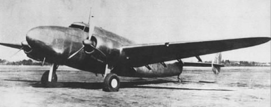
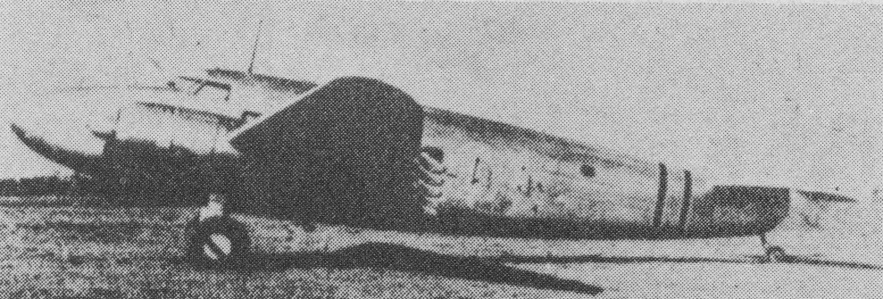
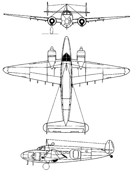
Developed from the Lockheed 14 transport built by the Kawasaki Company under licence, the Ki-56 had an enlarged fuselage with a large freight loading door in the port rear-fuselage side. Powered by two 671kW Ha-26-II radial engines, two prototypes were followed by 119 series-built machines designated Army Type 1 Freight Transport (assembled between 1941 and 1943).
56 were manufactured for the army by Kawasaki before production was handed over to Tachikawa who built a further 688.
Widely used in the Pacific war, the Ki-56 was coded Thalia by the Allies.
Engines: 2 x Nakajima Ha-25, 740kW / 990 hp Take-off weight: 8025 kg / 17692 lb Empty weight: 4895 kg / 10792 lb Wingspan: 19.96 m / 64 ft 6 in Length: 14.9 m / 48 ft 11 in Height: 3.6 m / 11 ft 10 in Wing area: 51.2 sq.m / 551.11 sq ft Max. speed: 400 km/h / 249 mph at 11,155 ft Ceiling: 8000 m / 26250 ft