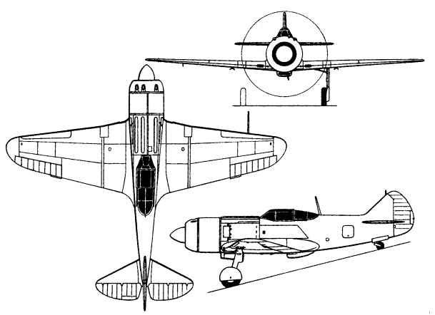
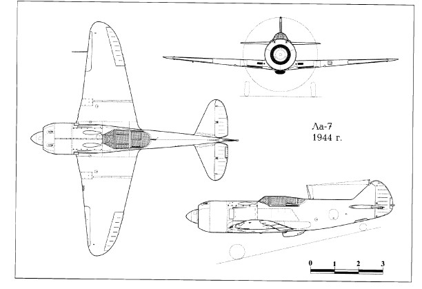
The La-7 was developed from the autumn of 1943 under the bureau designation of La-120. This embodied the results of a TsAGI wind tunnel programme aimed at defining areas in which the basic La-5FN could be aerodynamically improved. Incorporating the modified wing structure (metal spars replacing the wooden box spars) intended for application to the definitive La-5FN (but not to be introduced on that fighter until the late spring of 1944), a revised inboard wing leading edge and an entirely new cowling for the Shvetsov M-82FN engine, the La-120 was first flown in November 1943. In the following spring it entered production as the La-7.
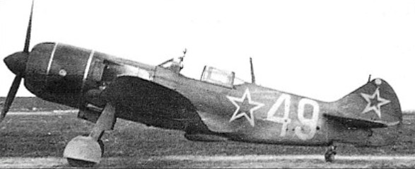
The intended armament comprised three 20mm Berezina B-20 cannon, but while this armament was installed in aircraft built at Yaroslavl, those built at Moscow reverted to the twin ShVAK cannon of the La-5FN.
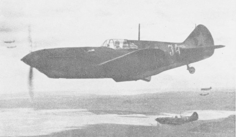
The first series production La-7 were produced in March-April of 1944. That Summer they were handed over to the pilots of 63 GIAP for operational trials. Though they had inferior performance to what was expected the pilots enjoyed great success with this aircraft until engine problems and wing spar failures forced Marshal Novikov to step in an ground all La-7s until the problems could be rectified. The causes were dirt getting into the supercharger air intake at the wingroots and improper execution of lightening holes in the structure. In November 1944 all production irregularities had been worked out and production resumed of the La-7.
La-7
The last war time production model was unchanged except the armament. In February 1945 3xB-20s became the standard armament. Weight was increased to 7,325 but performance was unchanged.
115 La-7 were lost to all military causes (less than half of these to aerial combat) and at the same time accounting for more than 3,100 aerial victories.
Roll rate was considered equal to any Fw-190A.
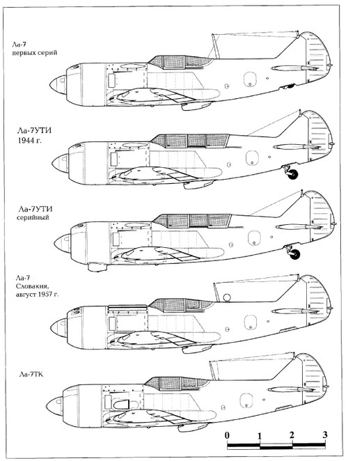
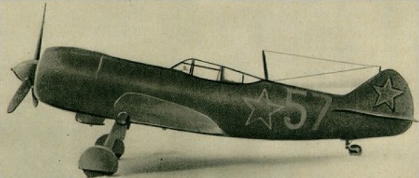
Variants included the tandem two-seat La-7UTI trainer, the La-7TK with a pair of TK-3 turbo-superchargers, and the rocket-boosted La-7R. The La-7TK was test flown in July- August 1944, but was destroyed when a turbo-supercharger exploded. Another example was fitted with the 2000hp ASh-71TK, trials soon being discontinued owing to the erratic behaviour of this engine’s turbosuperchargers.
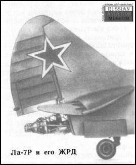
The La-7R, of which two prototypes were tested, was fitted in the rear fuselage with an RD-lKhZ liquid rocket motor of 300kg thrust, the first prototype being destroyed during the initial take-off run in October 1944. Flight testing of the second prototype continued until February 1945, and a further example – a conversion of one of the original prototype airframes and then referred to as the La-120R – entered test in January 1945, this having an improved rocket motor and local airframe structural changes. Testing of the La-120R continued until late 1946.
A total of 5,753 La-7s had been manufactured when production ended in 1946.
Engine: Shvetsov M-82FN, 1850hp Max take-off weight: 3400 kg / 7496 lb Empty weight: 2620 kg / 5776 lb Wingspan: 9.8 m / 32 ft 2 in Length: 8.6 m / 28 ft 3 in Height: 2.60 m / 8 ft 6 in Wing area: 17.59 sq.m / 189.34 sq ft Max. speed: 680 km/h / 423 mph Cruise speed: 450 km/h / 280 mph Ceiling: 11800 m / 38700 ft Range: 990 km / 615 miles Crew: 1
La-7 Engine: ASh-82FN, 1,850hp. Max speed: 362mph/SL Max speed: 413mph/20,200ft. Climb: 4,000fpm/SL. Climb to 16,400ft: 4.6min. Ceiling: 31,000ft. Armament: 2xShVAK. Test weight: 7,179 lbs.
La-7 Engine: Shvetsov M-82FN, 1850hp Max speed: 382mph/SL. Max speed: 421-423mph/20,200ft. Climb SL: 4,300fpm Climb to 16,400ft: 4.2min. Ceiling: 34,450ft. Test weight 7,105 lbs. Armament: 2xShVAK (20mm).
La-7 Engine: Shvetsov M-82FN, 1850hp Max speed: 382mph/SL. Max speed: 421-423mph/20,200ft. Weight: 7,325 Armament: 3x20mm Berezina B-20 cannon
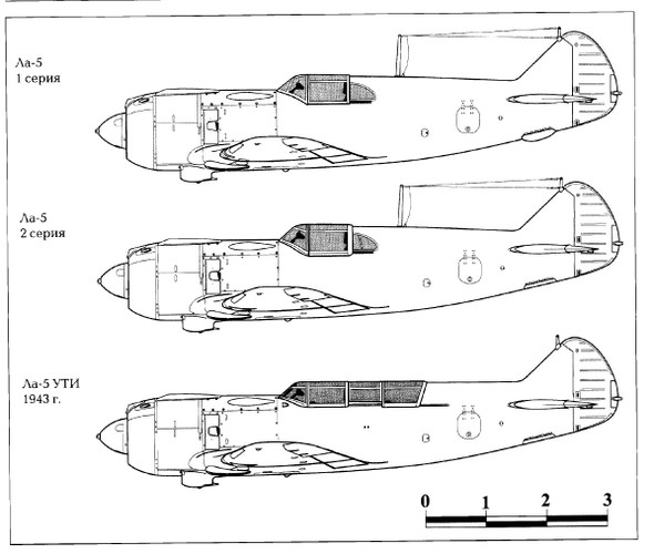
In late 1941 it was decided to improve the performance of the LaGG-3 by installing the more powerful 1600 hp Ash-82A radial engine. The basic LaGG-3 airframe was adapted for a 14- cylinder two-row radial Shvetsov M-82 engine without major redesign (examples converted from existing LaGG-3 airframes on the production line sometimes being referred to as LaG-5s). Despite its fractionally greater installed drag, 1%, it offered speed increase from 353 to 373 mph and improved all-round performance at height. The liquid-cooled fighter was cancelled in May 1942, all production switching to the new machine, designated LaGG-5. With in a few weeks this in turn was replaced om the assembly line by a further improvement, tested as a prototype early in 1942, with a new fuselage containing two 20mm guns and having a lower rear profile behind a canopy giving all-round vision. This was the La-5 which proved to be 28 mph faster than the Bf 109G-2 below 20,000 ft. But the German fighter could outclimb it and efforts were made to reduce weight.
The prototype conversion was first flown in March 1942 with an M-82 rated at 1700hp for take-off, and the La-5 was cleared for service testing in the following September with an armament of two 20mm cannon. Early machines retained the cockpit and rear fuselage construction of the earlier fighter.
With completion of the conversion of existing LaGG-3 airframes, minor changes were introduced in new production aircraft, the principal of these being the cutting down of the aft fuselage decking and the introduction of a 360 degree vision canopy.
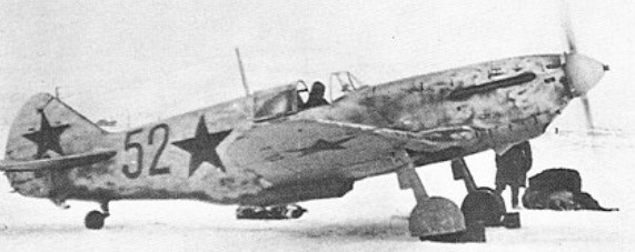
The designed earned Lavochkin the title of Hero of Socialist Labour, and the La-5 made its operational debut at the Battle of Stalingrad in October 1942.
A further development of the La-5AV became the La-7.
Late in 1942, the improved M-82F engine became available, producing 1650hp at 1650m, aircraft fitted with this engine being designated La-5F, and, from early 1943, fuel tankage was revised.
From late March 1943, the fuel injection M-82FN engine offering 1850hp for take-off replaced the carburettor-equipped M-82F, and with this power plant the fighter became the La-5FN. This version fought in the Battle of Kursk, and was produced in fairly substantial numbers.
La-5FN
When the La-5 was withdrawn from production late in 1944, a total of 9,920 aircraft of this type (including La-5UTI two-seat trainers) had been built.
La-5FN Engine: Shvetsov M-82FN, 1850hp Max take-off weight: 3360 kg / 7408 lb Empty weight: 2800 kg / 6173 lb Wingspan: 9.8 m / 32 ft 2 in Length: 8.60 m / 28 ft 3 in Height: 2.54 m / 8 ft 4 in Wing area: 17.50 sq.m / 188.37 sq ft Max. speed: 648 km/h / 403 mph Ceiling: 11000 m / 36100 ft Range: 765 km / 475 miles
La-5FN Engine: Shvetsov ASh-82FN, 1640hp Wingspan: 9.8 m / 32 ft 2 in Length: 27 ft 10 in Height: 9 ft 3 in Empty weight: 6085 lb Loaded weight: 7406 lb Max. speed: 402 mph at SL Service ceiling: 11000 m / 36, 000 ft Max range: 528 miles Seats: 1 Armament: 2 x 20 mm ShVAK cannon Bombload: 330 lb
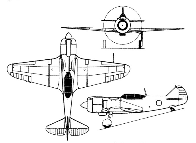
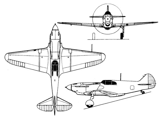
Various remedies for the handling shortcomings of the LaGG-1 were applied, and the first LaGG-1 prototype to introduce these changes was referred to as the I-301 (from the numerical designation of the factory – GAZ-301). This also featured redesigned outer wing panels incorporating additional fuel tanks. The I-301 entered flight test on 14 June 1940, the modified aircraft being assigned the designation LaGG-3 and most pre-series examples of the LaGG-1 being completed to the later standard.
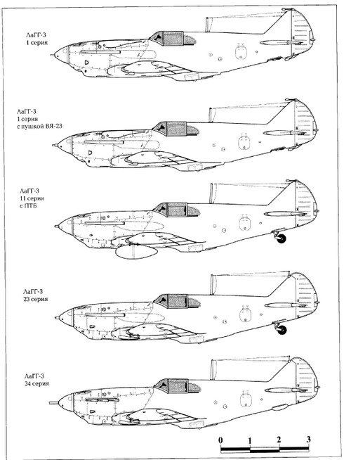
The LaGG-3 was essentially the series production version of the LaGG-1 with a revised outer wing incorporating fuel tanks, and an armament of one 20mm and two 7.62mm weapons. Fixed wing slats – later replaced by automatic slats – were introduced and balance weights were added on the elevators and rudder, but were later discarded in favour of statically and dynamically balanced surfaces. Weight was reduced as a result of a structural analysis. LaGG-3 deliveries commenced in the spring of 1941, initially with the M-105P engine, but, from late in the year, with the M-105PF of 1260hp at 800m.
Provision was later made to replace one or both machine guns by weapons of 12.7mm calibre, the 20mm hub-mounted cannon being replaced by one of 23mm calibre in some cases, and a pair of 12.7mm underwing guns was sometimes fitted. Three aircraft were each fitted with a 37mm cannon and referred to as LaGG-3K-37s, and one example was fitted with the 1650hp Klimov M-107A engine. Production of the LaGG-3 was completed in the late summer of 1942 with a total of 6,528 built, superseded by the La-5.
During 1941 Lavochin converted one LaGG-3 to have an M-82 radial engine. Despite its fractionally greater installed drag, 1%, it offered speed increase from 353 to 373 mph and improved all-round performance at height. The liquid-cooled fighter was cancelled in May 1942, all production switching to the new machine, designated LaGG-5.
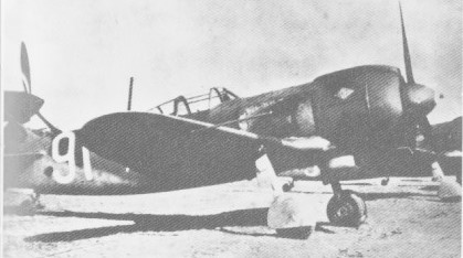
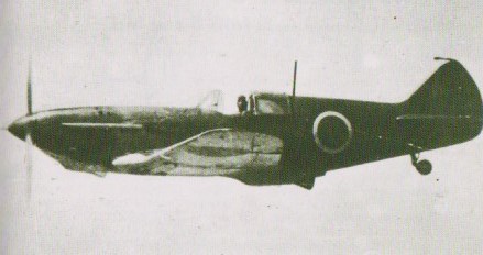
Flown to Manchuris by a Russian deserter and tested by Japanese in 1942 at Harbin
LaGG-3 Engine: Klimov M-105, 1100 hp Wingspan: 9.8 m / 32 ft 2 in Wing area: 17.5 sq.m / 188.37 sq ft Length: 8.9 m / 29 ft 2 in Height: 8 ft 10 in Empty weight: 2620 kg / 5776 lb Max take-off weight: 3190 kg / 7033 lb Max. speed: 570 km/h / 354 mph at 16,400 ft Cruise speed: 450 km/h / 280 mph ROC: 2953 fpm / 900 m/min Ceiling: 9700 m / 31800 ft Range: 800 km / 497 miles Armament: 1 x 20 mm ShVAK cannon, 1 x 12.7mm Beresin mg, 2 x 7.62mm ShKAS mg
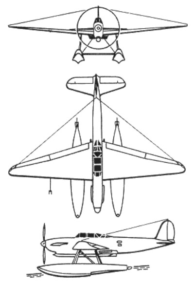
In the early 1930s, the Marine nationale (French navy) was looking to replace its aging Levasseur PL15 and Latécoère 290 torpedo seaplanes. The new aircraft had to be stable in flight, drop torpedoes, dive-bomb, and carry out long-range reconnaissance patrols. Late 298 was designed in the Bureau at the Latecoire plant in Toulouse in 1934. It had to meet the requirements of the task for a modern float torpedo carrier, issued by the fleet command a year earlier. It was assumed that this aircraft will replace Late 29.0.
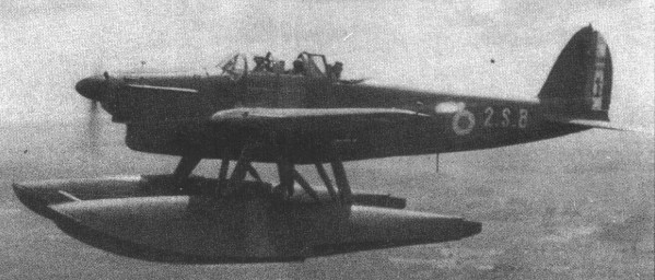
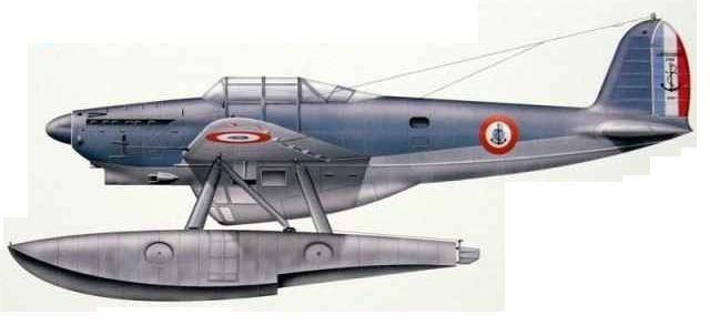
The Laté 298 was a monoplane with large floats, metal structure, and a metal skin with some fabric-covered parts, powered by a Hispano-Suiza 12Ycrs inline engine that drove a Ratier variable-pitch propeller. The radiators were retractable and located below the wing roots. One pilot, one rear gunner, and one navigator/radio operator (who was carried only if required) operated the aircraft. Ordnance could be attached under the fuselage, with provision for a type 1926 DA 670 kg torpedo semi-recessed into the underside of the fuselage. The fuselage could not accommodate the desired 20-mm (0.79-in) Hispano-Suiza HS.9 cannon, leaving forward firing armament to consist of only two 7.5-mm (0.295-in) Darne machine guns in the wings. The rear gunner manned a single mobile weapon of the same type. Intended missions included torpedo bombing; horizontal or shallow dive bombing (with two bombs of up to 150 kg each); long-range reconnaissance (with extra 535 litre fuel tank); night reconnaissance; and smokescreen laying. In each of the floats there was a 260 liters fuel tank. The horizontal wing was all-metal, and the vertical fin had metal frames and wooden ribs, fabric covered. The floats were attached to the wings with N-shaped struts and paired struts to the fuselage.
The Aéronautique navale (naval aviation) authorities accepted the project for evaluation, and SILAT built the first prototype in Toulouse-Montraudan. The Late 298-01 was collected in the spring of 1936 and transported to Saint-la-Raur-de-la-Salanca, where tests were to be conducted on Lake Locate. Its maiden flight took place May 8, 1936 from St-Laurent-de-la-Salanque.
The plane flew 24 hours and 35 minutes on tests. Factory tests ended on September 24, 1936. During the tests a strut was installed between the two floats. It was preserved on all subsequent machines. On September 25, Late 298-01 flew to Saint-Raphael for official tests.
On June 22, 1938 Late 298-01 took to the air with a Ratier automatic prop. Equipped with an electrical control step, similar to that of the first production aircraft in Biskarossa. Fuselages and floats for them were manufactured in Montadran, and wings and tail fins in Angle near Bayonne.
On March 17, 1937, the French fleet ordered 36 seaplanes, 12 of which were to be distinguished by the folding of the outer sections of the wing for operation at the Commandan Test.
Since October 28, 1938, the Late 298-01 began to be used for retraining pilots in Saint-Raphael, where they were temporarily deployed by squadron T2. At the beginning of the next month, the personnel of the T1 squadron joined the retraining process.
Accordingly, on August 10, contracts were signed for 24 Late 298A aircraft without folding the wing and 12 Late 298B with folding of the outer sections of the wing.
A cantilever low-wing monoplane with an all-metal oval-section stressed-skin fuselage, production orders were placed for 177 Latecoère 298s in three variants. The first production Late 298A flew in October 29 in Biskarossa.
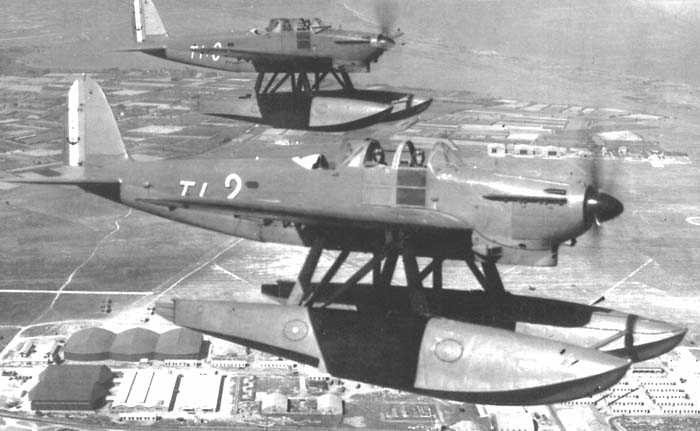
The first examples delivered to operational units, in January 1939, equipped Escadrille (Flight) T2, based in Cherbourg. Escadrille T1, based in Berre, adopted the type shortly thereafter, as did Escadrilles HB1 and HB2, which, while theoretically assigned to the seaplane carrier Commandant-Teste, never flew Latés – which were not designed for catapult launches – from the ship. Early in deployment, two fatal accidents revealed that the crews needed supplementary training to handle these modern highly wing-loaded aircraft. T3 received its seaplanes in September 1939 and T4 was so equipped in early 1940.
In early 1939 squadron HB1 received Late 298A before the appearance of the Late 298B with folding wings. The serial Late 298A was very close to the Late 298-01 except for the cockpit, redesigned to improve visibility. The production Late 298A was powered by a 656kW / 880 hp Hispano-Suiza 12Ycrs engine and had a crew of three accommodated under a new glazed canopy by comparison with the prototype.
The 42 Latecoere 298Bs featured dual controls and folding wings for shipboard stowage. Armament comprised two fixed 7.5mm Darne wing guns and a third Darne machine-gun on a flexible mounting at the rear of the crew canopy. The Late 298B also provided for the deployment of a fourth crew member, an observer. Both modifications were carried by the TGPU / CERA torpedo carrier, on which it was possible to suspend an additional fuel tank with a capacity of 534 liters (for the so-called IIP reconnaissance with a flight range up to 2200 km) or a smoke device (for “task V” – cover for ships ) The armament could be supplemented with two GPU bomb detonators for 150 kg bombs (for “task II” -bombing) or nine holders for lighting missiles (for “task IV” – night reconnaissance).
The serial aircraft of the Late 298A type learned factory numbers from 1 up to 24, and Late 298 B numbers began with 25. On April 2, 1938, and a new order for 15 Late 298B (NN 37-51) and five Late 298D (NN 52-56), the last modification was similar to type B, but the wing did not fold. The designation Late 298C was assigned with modifications that were not implemented.
The next series of 25 Late 298D (NN957-81) was ordered on April 5, 1939, but the lack of Ratier propellers held back production and on August 29 it was decided to temporarily install two-blade wooden Xavier fixed pitch props. The use of this propeller forced to reduce the normal take-off weight from 4600 kg to 4,400 kg, and also to lay a ballast of 55 kg, attached to the second frames of both floats.
At the beginning of World War II, the French fleet had four squadrons armed with Late 298. These were the T1 in Berrre, T2 in Cherbourg, HB1 and HB2 aboard the Commandant Test. September 15, 1939 formed a squadron of TZ, which received the same type. By the beginning of the next month, the fleet had 53 seaplanes Late 298, another 28 were waiting for the delivery by the military. November 22, 1939 ordered an additional 65 aircraft.
With the declaration of war in 1939, T2 began to patrol the English Channel in an uneventful hunt for German submarines, but the unit would face the more substantial threat of German ground forces the next year. On May 19, the Armée de l’air headquarters of the Zone d’opérations aériennes Nord (Northern France air operations zone; ZOAN), overwhelmed by German pressure, requested help from the Aéronautique navale. The commander-in-chief of the Forces maritimes du Nord (Northern France naval forces) at first committed its naval dive-bombers to the ground battle, and, on May 23, ordered T2 to destroy an enemy armoured column “somewhere between Abbeville and Boulogne”. The headquarters officers of the Aéronautique navale tried to help stem the German invasion but were not necessarily well informed about modern air war and the capabilities of the naval aircraft under their command.
Despite the T2 commander’s protests that his aircraft were only equipped with anti-shipping bombs and his crews were not trained to attack ground targets, the order was confirmed – anything that might slow down the Germans was to be attempted. On the first sortie, the crews of the Laté 298s could not locate the target column, but one of the seaplanes was shot down by flak. Another four T2 Latés took off for a second attack on the same poorly defined target, and this time encountered nine Bf 110s of I./JG 27. Only one Laté made it back home. Even more desperate missions of this type were carried out by the crews of T2 and T3.
The 106 Latecoere 298Ds had dual controls and a fourth crew member, but fixed wings.
One Latecoere 298D was modified as a Latecoere 298E with an underfuselage reconnaissance gondola but was found unsatisfactory.
Laté 298E Obs. version with belly gondola, Laté 298D conv.
110 Late 298 of all versions had been built by 25 June 1940 and after the Armistice of June 1940, 30 single-control Latecoêre 298Fs were built for overseas use by the Vichy forces. The 298F had MAC instead of Darne weapons and two additional 7.7mm machine-guns for ventral ‘under-tail’ defence.
The first naval escadrilles to equip with the type were T2 at Saint-Raphael and T1 at Berre in February and March 1939 respectively. Escadrilles HB1 and HB2 on the seaplane carrier Commandant Teste re-equipped with Late 298B in April and July the same year. From then on the type saw widespread service, flying overland in shallow dive-bombing attacks during the May-June 1940 ‘Blitzkrieg’ on France and subsequently continuing to operate – mainly on reconnaissance missions – with both the Vichy and Free French forces. Several captured aircraft were used for liaison duties by the Germans.
Following Italy’s declaration of war on France, the Laté 298-equipped units were redirected towards the Mediterranean. Escadrilles T2 and HB2 engaged a few Italian naval targets, with little result, shortly before the Armistice came into effect. By then, most torpedo seaplanes had been evacuated to North Africa, with the exception of Escadrille T4, which had been training and remained in southern France.
According to Armistice terms, all French aircraft were grounded, but after the Royal Navy attack on the French fleet in Mers el-Kébir, maritime patrol off the North African coast became a regular duty for the crews. In spite of the Royal Navy attack, one Latécoère crew defected to British-held Malta in July 1940. The airmen joined the RAF, and their aircraft, repainted in RAF colours, was used operationally for reconnaissance and leaflet dropping. Most Latés saw little use during the Armistice period as several units were disbanded at German request. Vichy France sent Escadrille 1T (formerly T1) to the Levant States in summer 1941 to help fend off British and Free French forces, but the unit arrived too late and without the equipment to play a significant part in the fratricidal conflict before Syria and Lebanon fell.
The Operation Torch landings in North Africa did not mark the end of the Laté’s career, as it did for many other French aircraft types. The need to secure the new Allied stronghold in the Mediterranean forced the Marine nationale to use the Latés for coastal patrol, as a complement to other Allied types such as the Supermarine Walrus.
When German forces invaded southern France in November 1942, they captured 54 Laté 298s. The Italians expressed an interest in acquiring the seaplanes but did not receive them before surrendering to the Allies. The Germans, having evaluated two examples captured in 1940, planned to convert the 45 remaining airworthy Latés for use by Luftwaffe units. Machine guns, bomb racks, and radio sets were to be replaced by standard German equipment. A single converted example was tested in May 1944, but the project came to an abrupt end when in August the Allies landed in southern France, where the Latés were stationed.
After the war, the Aéronautique navale found itself in control of a large number and wide variety of seaplane and flying boat types, including Allied aircraft such as Consolidated Catalinas, Short Sunderlands, Supermarine Sea Otters, ex-Luftwaffe Dornier Do 24s, and even Japanese-built aircraft captured in French Indochina. The Latécoère 298 was assigned trainer duties with Escadrille 53.S before being phased out of service in 1951.
Variants: Laté 298 Series – 1934 design, low-wing monoplane torpedo bomber NB: Laté 298 design was a successor to the Laté 29, not a variant Laté 298-01: 1936 prototype, 1 x 880 hp HS.12Ycrs1, 1 built Laté 298-01 tests successful, float spreader bar added Laté 298A: coastal patrol model, revised canopy, 24* built
24 x Laté 298A ordered in 1937, some sources claim 30 built Laté 298B: folding wing version, crew inc. from 3 to 4, 42 built Laté 298B for use on floatplane carrier Commandant Teste Laté 298C: [Project] floatplane (but details unknown) Laté 298D: as per Laté 298A but with Laté 298B wings, 75 built Laté 298E: Obs. version with belly gondola, 1 x Laté 298D conv. Laté 298F: 1942 simplified Laté 298D ordered for Vichy, 30 built Laté 298D total of 75 built may also incl. Laté 298F production
Late 298 Engine: 1 x HS 12 Ycrs, 630kW Wingspan: 15.5 m / 50 ft 10 in Length: 12.6 m / 41 ft 4 in Height: 5.2 m / 17 ft 1 in Wing area: 31.6 sq.m / 340.14 sq ft Max take-off weight: 4123 kg / 9090 lb Empty weight: 2360 kg / 5203 lb Max. speed: 270 km/h / 168 mph Cruise speed: 243 km/h / 151 mph Range w/max.payload: 800 km / 497 miles Armament: 3 machine-guns, 1700kg torpedo Crew: 3
Late 298A Engine: l x Hispano-Suiza engine 12Ycrs-1, 880 hp Wingspan: 15.50 m Wing area: 31.60 sq.m Length: 12.56 m Height: 5.25 m Gross weight: 4517 kg Maximum speed: 286 km / h at 2500 m Ceiling: 5100 m Range: 1000 km Armament: Three 7.5 mm machine guns Bombload: 1 torpedo 670 or 500 kg of bombs Crew:3
Late 298A Modified Engine: l x Hispano-Suiza engine 12Ycrs-1, 880 hp Wingspan: 15.50 m Wing area: 31.60 sq.m Length: 12.56 m Height: 5.25 m Empty weight: 3060 kg Take-off weight: 4795 kg Maximum speed: 290 km / h Cruising speed: 245 km / h Range: 2200 km Rate of climb: 268 m / min Ceiling: 6500 m Crew: 3 Armament: two fixed and one manual 7.5-mm Darne Mle 1933 mg Bombload: one 670-kg Type 1926 DA torpedo or 500 kg bombs, or three depth charges, or nine flares.
Latecoère 298D Engine: l x Hispano-Suiza 12Ycrs-1, 656kW (880hp). Propeller: 3-bladed variable-pitch Span: 15.5m (50ft 10.25 in). Wing area: 31.6 m2 (340 sq ft) Airfoil: Clark CYH Length: 12.56m (4lft 2.5in). Height: 5.25 m (17 ft 1.75 in) Empty weight: 3,057 kg (6,750 lb) Max T/O weight: 4600kg (10,141 lb). Maximum speed: 295 km/h (183 mph, 159 kn) at 2,500 m (8,202 ft) Service ceiling: 6,397 m (21,325 ft) Time to altitude: 1,000 m (3,281 ft) in 6 minutes 33 seconds Range: 1,000 km (620 mi, 540 nmi) Armament: 3 x 7.5-mm (0.295-in) Darne mg Bombload: 1 x 670-kg (1,477-lb) torpedo, or 500 kg (1,102 lb) bombs, or 3 x depth bombs. Crew: 2 to 4, usually 3
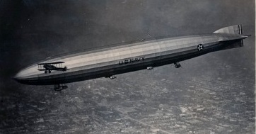
USS Shenandoah was the first of four United States Navy rigid airships. The design was based on Zeppelin bomber L-49 (LZ-96), built in 1917 which had been forced down intact in France in October, 1917 and carefully studied. L-49 was a lightened Type U “height climber”, designed for altitude at the expense of other qualities.
The L-49 was one of the “height climbers” designed by the Germans late in World War I, when improvements in Allied fighter aircraft and anti-aircraft artillery made it necessary for Zeppelins to climb to great altitudes to avoid being shot down. For the Zepeplins to rise to greater heights on a fixed volume of lifting gas, however, the weight and strength of their structures were dramatically reduced. This decrease in strength was accepted as a wartime necessity, since a structurally weaker Zeppelin flying above the reach of enemy aircraft and artillery was safer than a stronger Zeppelin that could be easily attacked.
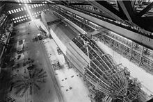
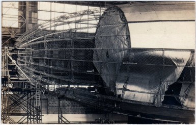
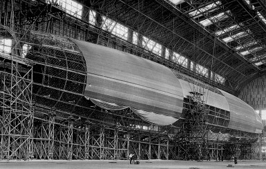
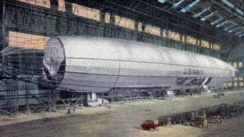
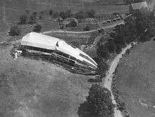
Shenandoah under construction at Lakehurst in 1923
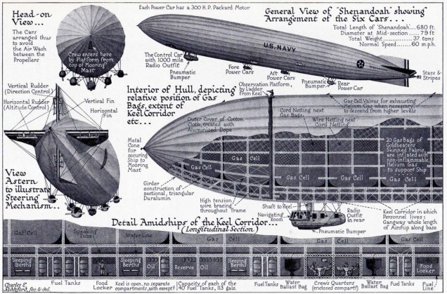
The design was found insufficient and a number of the features of newer Zeppelins were used, as well as some structural improvements. The structure was built from a new alloy of aluminum and copper known as duralumin. Girders were fabricated at the Naval Aircraft Factory. Whether the changes introduced into the original design of L-49 played a part in Shenandoah’s later breakup is a matter of debate. An outer cover of high-quality cotton cloth was sewn, laced or taped to the duralumin frame and painted with aluminum dope.
The gas cells were made of goldbeater’s skins, one of the most gas-impervious materials known at the time. Named for their use in beating and separating gold leaf, goldbeater’s skins were made from the outer membrane of the large intestines of cattle. The membranes were washed and scraped to remove fat and dirt, and then placed in a solution of water and glycerine in preparation for application to the rubberized cotton fabric providing the strength of the gas cells. The membranes were wrung out by hand to remove the water-glycerine storage solution and then rubber-cemented to the cotton fabric and finally given a light coat of varnish. The 20 gas cells within the airframe were filled to about 85% of capacity at normal barometric pressure. Each gas cell had a spring-loaded relief valve and manual valves operated from the control car.
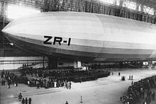
Shenandoah was originally designated FA-1, for “Fleet Airship Number One” but this was changed to ZR-1. The airship was 680 ft (207.26 m) long and weighed 36 tons (32658 kg). It had a range of 5,000 mi (4,300 nmi; 8,000 km), and could reach speeds of 70 mph (61 kn; 110 km/h). Shenandoah was assembled at Naval Air Station Lakehurst, New Jersey in 1922–1923, in Hangar No. 1, the only hangar large enough to accommodate the ship; its parts were fabricated at the Naval Aircraft Factory in Philadelphia. NAS Lakehurst had served as a base for Navy blimps for some time, but Shenandoah was the first rigid airship to join the fleet.
Like all previous zeppelins, ZR-1 had been designed on the assumption that the ship would be operated with hydrogen, but the fiery crash of the U.S. Army airship Roma in 1922 convinced the U.S. government to operate future airship’s with helium, despite the high cost and very limited supply of the gas.
As the first rigid airship to use helium rather than hydrogen, Shenandoah had a significant edge in safety over previous airships. Helium was relatively scarce at the time, and the Shenandoah used much of the world’s reserves just to fill its 2,100,000 cubic feet (59,000 cu.m) volume. Los Angeles—the next rigid airship to enter Navy service, originally built by Luftschiffbau Zeppelin in Germany as LZ 126—was at first filled with the helium from Shenandoah until more could be procured.
Shenandoah was powered by 300 hp (220 kW), eight-cylinder Packard gasoline engines. Six engines were originally installed, but in 1924 one engine (aft of the control car) was removed. The first frame of Shenandoah was erected by 24 June 1922; on 20 August 1923, the completed airship was floated free of the ground. Helium cost $55 per thousand cubic feet at the time, and was considered too expensive to simply vent to the atmosphere to compensate for the weight of fuel consumed by the gasoline engines. Neutral buoyancy was preserved by installing condensers to capture the water vapor in the engine exhaust. The need to preserve helium had many operational implications, including the timing of flights to coordinate with changes in ambient temperature.
The Navy also had to learn how to use helium to operate a large rigid airship, which had never previously been attempted. The need to conserve the expensive and scarce lifting gas required flight operations which differed considerably from the techniques which had been developed for operating airships inflated with easily-replaced hydrogen. For example, while the Germans typically began a zeppelin flight with gas cells inflated to 100% capacity, and then valved hydrogen (either manually or automatically) as the ship rose, the Americans — unable to afford the loss of precious helium — had to operate with lower inflation levels, and therefore less lift, and had to be more careful about valving gas to descend or to maintain aerostatic equilibrium.
Shenandoah first flew on 4 September 1923. ZR-1 made a series of test and demonstration flights in September and early October, 1923 — including an appearance at the National Air Races in St. Louis and flights over New York and Washington.
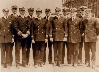
Officers of the USS Shenandoah on her first flight (left to right): Lieut. A.R. Houghton, Lieut. L.E. Mueller, Cdr. J.H. Klein, Lieut. C.E. Rosendahl, Lieut. Cdr. M.R. Pierce, Lieut. J.C. Arnold, Lieut. E.H. Kincaid, Lieut. H.V. Wiley, Lieut. R.J. Miller, Lieut. R.F. Tyler, Lieut. J.B. Andserson
Christening ceremonies for USS Shenandoah (ZR-1)
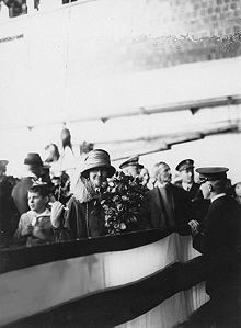
It was christened on 10 October 1923 by Mrs. Edwin Denby, wife of the Secretary of the Navy, and commissioned on the same day with Commander Frank R. McCrary in command. Mrs. Denby named the airship after her home in the Shenandoah Valley of Virginia, and the word shenandoah was then believed to be a Native American word meaning “daughter of stars”.
Mrs. Edwin Denby ready to christen USS Shenandoah, October 1923
Shenandoah was designed for fleet reconnaissance work of the type carried out by German naval airships in World War I. Her precommissioning trials included long-range flights during September and early October 1923, to test her airworthiness in rain, fog and poor visibility. On 27 October, Shenandoah celebrated Navy Day with a flight down the Shenandoah Valley and returned to Lakehurst that night by way of Washington and Baltimore, where crowds gathered to see the new airship in the beams of searchlights.
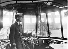
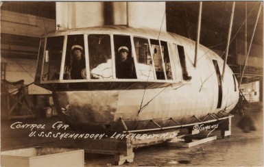
1923 control gondola of the USS Shenandoah. Commander McCrary, the ship’s commander, at the wheel.
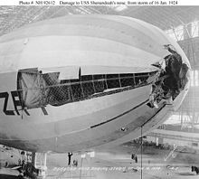
At this time, Rear Admiral William A. Moffett—Chief of the Bureau of Aeronautics and staunch advocate of the airship—was discussing the possibility of using Shenandoah to explore the Arctic. He felt such a program would produce valuable weather data, as well as experience in cold-weather operations. With its endurance and ability to fly at low speeds, the airship was thought to be well-suited to such work. President Calvin Coolidge approved Moffett’s proposal, but Shenandoah’s upper tail fin covering ripped during a gale on 16 January 1924, and the sudden roll tore her away from the Lakehurst mast, ripping out her mooring winches, deflating the first helium cell and puncturing the second. Zeppelin test pilot Anton Heinen rode out the storm for several hours and landed safely while the airship was being blown backwards. Extensive repairs were needed, and the Arctic expedition was scrapped.
Shenandoah’s damaged bow following the January storm
On February 12, 1924, while it was undergoing repairs, Shenandoah received a new commanding officer, Lt. Cdr. Zachary Lansdowne.
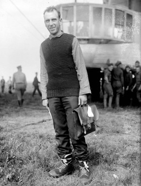
Zachary Lansdowne in front of R-34
Lansdown, a 1909 graduate of the United States Naval Academy, was one of the Navy’s first officers trained in lighter-than-air aviation. He trained with the crew of the British airship R-34, and became the first American to cross the Atlantic nonstop by air as the American naval observer aboard R-34’s 1919 transatlantic flight. After service as a White House aide, Lansdowne was the Assistant Naval Attache in Germany in 1922-1923, where was involved with the negotiations for the construction of the LZ-126, which became the ZR-3 USS Los Angeles.
The ship was grounded for repairs until May 22, 1924, when it was returned to service with reinforcements to its mooring assembly, nose, and fins. The sixth engine in its control car was also removed and replaced with radio equipment, including a long distance direction finding set.
Airship USS Shenandoah during repairs, March-April, 1924.
Shenandoah’s repairs were completed in May, and the summer of 1924 was devoted to work with its engines and radio equipment to prepare for fleet duty. In August 1924 it reported for duty with the Scouting Fleet and took part in tactical exercises. Shenandoah succeeded in discovering the “enemy” force as planned but lost contact with it in foul weather. Technical difficulties and lack of support facilities in the fleet forced it to depart the operating area ahead of time to return to Lakehurst. Although this marred the exercises as far as airship reconnaissance went, it emphasized the need for advanced bases and maintenance ships if lighter-than-air craft were to take any part in operations of this kind.
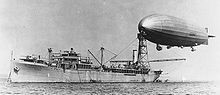
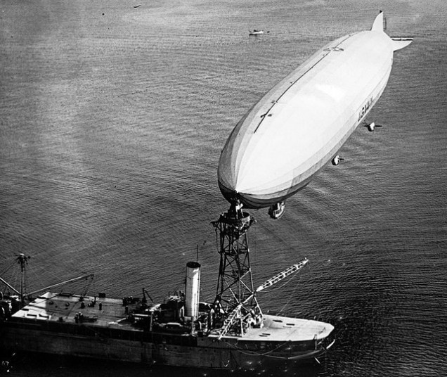
In July 1924, the oiler Patoka put in at Norfolk Naval Shipyard for extensive modifications to become the Navy’s first airship tender. An experimental mooring mast 125 ft (38 m) above the water was constructed; additional accommodations both for the crew of Shenandoah and for the men who would handle and supply the airship were added; facilities for the helium, gasoline, and other supplies necessary for Shenandoah were built, as well as handling and stowage facilities for three seaplanes. Lansdowne conducted pioneering operations in which he moored Shenandoah to a mast installed on the support ship Patoka, to show the possibility of underway replenishment and supply to extend the ship’s range and allow an airship to work closely with the fleet, and Lansdowne conducted operations with surface ships such as the battleship USS Texas whenever possible. The first successful mooring was made on 8 August. During October 1924, Shenandoah flew from Lakehurst to California and on to Washington State to test newly erected mooring masts. This was the first flight of a rigid airship across North America.
Shenandoah moored to the oiler Patoka
1925 began with nearly six months of maintenance and ground test work. Shenandoah did not take to the air until 26 June, when it began preparations for summer operations with the fleet. In July and August, it again operated with the Scouting Fleet, successfully performing scouting tasks and being towed by Patoka while moored to that ship’s mast.
ZR-1 Shenandoah moored to USS Patoka at sea
Shenandoah made one of its most impressive demonstrations in October, 1924, when the ship made a difficult 19-day journey across the United States from Lakehurst to San Diego, via Forth Worth, and then traveled up the west coast to Seattle and back to San Diego, before returning to Lakehurst via Fort Worth. Shenandoah logged 235 flight hours on its headline-making journey across the country, and captured the enthusiasm of both the American public and also leaders in the field of aviation around the world.
Upon Shenandoah’s return to Lakehurst the ship was was deflated so that its helium could be transferred to the newly arrived ZR-3 (soon to be commissioned USS Los Angeles) which had just been delivered to Lakehurst by Hugo Eckener and his German crew; the supply of helium was so scare in 1924 that the United States did not have enough of the gas to inflate two large airships at the same time.
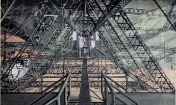
Keel of the U.S. Navy Airship Shenandoah
During Shenandoah’s lay-up, Zachary Lansdowne made a decision which would later be highly controversial. In order to limit the loss of helium by leakage through the automatic valves, and to eliminate several hundred pounds of weight, Lansdowne ordered the removal of 10 of the ship’s 18 automatic gas valves. These valves automatically released helium when as the ship climbed, to avoid over-expansion of the cells at higher altitude, which could damage both the cells themselves and the surrounding framework. Lansdowne’s modification limited the amount of gas that could be valved in a given time, and meant that Shenandoah’s valves could not keep up with an increase of altitude greater than 400 feet per minute; at any higher rate of climb, the ship could not release enough helium to keep up with the expansion of the gas cells.
On 2 September 1925, Shenandoah departed Lakehurst on a promotional flight to the Midwest that would include flyovers of 40 cities and visits to state fairs. Testing of a new mooring mast at Dearborn, Michigan, was included in the schedule. While passing through an area of thunderstorms and turbulence over Ohio early in the morning of 3 September, during its 57th flight, the airship was caught in a violent updraft exceeding 1,000 feet per minute that carried it beyond the pressure limits of its gas bags to an altitude over 6,000 feet. Twisted by the storm, and the ship finally suffered catastrophic structural failure, breaking in two at frame 125, approximately 220 feet from the bow. The aft section sank rapidly, breaking up further, with two of the engine cars breaking away and falling to the ground. It crashed in several pieces near Caldwell, Ohio. Fourteen crew members, including Commander Zachary Lansdowne, were killed. This included every member of the crew of the control cabin (except for Lieutenant Anderson, who escaped before it detached from the ship); two men who fell through holes in the hull; and several mechanics who fell with the engines.
Control car of USS Shenandoah
There were twenty-nine survivors, who succeeded in riding three sections of the airship to earth. The largest group was eighteen men who made it out of the stern after it rolled into a valley. Four others survived a crash landing of the central section. The remaining seven were in the bow section which Commander (later Vice Admiral) Charles E. Rosendahl navigated as a free balloon. In this group was Anderson who—until he was roped in by the others—straddled the catwalk over a hole. Without the weight of the control car, the bow section, with seven men aboard, including Navigator Charles Rosendahl, ascended rapidly. Under Rosendahl’s leadership, the men in the bow valved helium from the cells and free-ballooned the bow to a relatively gentle landing.
The wreck of the Shenandoah Crash Site No. 3
The Shenandoah Crash Sites are located in the hillsides of Noble County. Site No. 1, in Buffalo Township, surrounded the Gamary farmhouse, which lay beneath the initial break-up. An early fieldstone and a second, recent granite marker identify where Commander Lansdowne’s body was found. Site No. 2 (where the stern came to rest) is a half-mile southwest of Site No. 1 across Interstate 77 in Noble Township. The rough outline of the stern is marked with a series of concrete blocks, and a sign marking the site is visible from the freeway. Site No. 3 is approximately six miles southwest in Sharon Township at the northern edge of State Route 78 on the part of the old Nichols farm where the nose of the Shenandoah’s bow was secured to trees. Although the trees have been cut down, a semi-circular gravel drive surrounds their stumps and a small granite marker commemorates the crash. The Nichols house was later destroyed by fire.
The crash site attracted thousands of visitors in its first few days. Within five hours of the crash more than a thousand people had arrived to strip the hulk of anything they could carry. On Saturday, 5 September 1925, the St. Petersburg Times of Florida reported that the site of the crash had quickly been looted by locals, describing the frame as being “[laid] carrion to the whims of souvenir seekers”. Among the items believed to have been taken were the vessel’s logbook and its barograph, both of which were considered critical to understanding how the crash had happened. Also looted were many of the ship’s 20 deflated silken gas cells, each worth several thousand dollars, most of them unbroken but ripped from the framework before the arrival of armed military personnel. Looting was so extensive that it was initially believed even the bodies of the dead had been stripped of their personal effects, and that operatives from the Department of Justice were being sent to investigate. That this was happening was soon denied by those publicly involved in the incident, however. Still, a local farmer on whose property part of the vessel’s wreckage lay began charging the throngs of visitors to enter the crash site at a rate of $1 (equivalent to about $13.60 in 2015) for each automobile and 25¢ per pedestrian as well as 10¢ for a drink of water.
On 17 September the Milwaukee Sentinel reported that 20 Department of Justice operatives had indeed been summoned to the site and that they along with an unspecified number of federal and state prohibition agents had visited private homes to collect four truck loads of wreckage along with personal grips of several crew members and a cap believed to have belonged to Commander Lansdowne. Lansdowne’s Annapolis class ring had also been thought to have been taken from his hand by looters as it was not then recovered-it was found by chance in June 1937 near the crash site # 1. No one was charged with any crime.
Two schools of thought developed about the cause of the crash. One theory is that the gas cells over-expanded as the ship rose, due to Lansdowne’s decision to remove the 10 automatic release valves, and that the expanding cells damaged the framework of the airship and led to its structural failure.
Official inquiry brought to light the fact that the fatal flight had been made under protest by Commander Lansdowne (a native of Greenville, Ohio), who had warned the Navy Department of the violent weather conditions that were common to that area of Ohio in late summer. His pleas for a cancellation of the flight only caused a temporary postponement: his superiors were keen to publicize airship technology and justify the huge cost of the airship to the taxpayers. So, as Lansdowne’s widow consistently maintained at the inquiry, publicity rather than prudence won the day. This event was the trigger for Army Colonel Billy Mitchell to heavily criticize the leadership of both the Army and the Navy, leading directly to his court-martial for insubordination and the end of his military career. Heinen, according to the Daily Telegraph, placed the mechanical fault for the disaster on the removal of eight of the craft’s 18 safety valves, saying that without them he would not have flown on her “for a million dollars”. These valves had been removed in order to better preserve the vessel’s helium, which at that time was considered a limited global resource of great rarity and strategic military importance; without these valves, the helium contained in the rising gas bags had expanded too quickly for the bags’ valves’ design capacity, causing the bags to tear apart the hull as they ruptured (of course, the helium which had been contained in these bags became lost into the upper atmosphere).
After the disaster, airship hulls were strengthened, control cabins were built into the keels rather than suspended from cables, and engine power was increased. More attention was also paid to weather forecasting.
Several memorials remain near the crash site. There is another memorial at Moffett Field, California, and a small private museum in Ava, Ohio.
ZR-1 USS Shenandoah Length: 680 feet Diameter: 79 feet Gas capacity: 2,115,000 cubic feet Useful lift: 48,774 lbs Maximum speed: 58 knots Crew: 40 officers and men First flight: September 4, 1923 Crashed: September 2-3, 1925 Total flight hours: 740:09
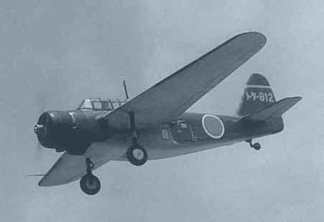
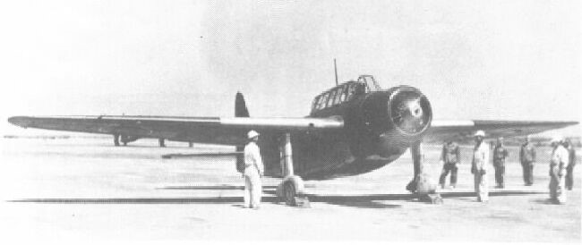
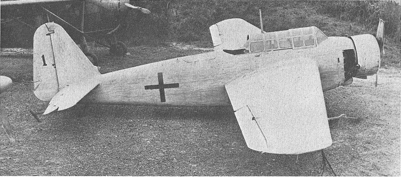
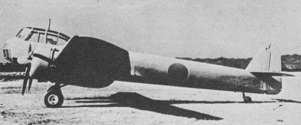
The Kyūshū K11W Shiragiku (白菊, “White Chrysanthemum”) made by the Kyūshū Aircraft Company, was a land-based bombing trainer aircraft which served in the Imperial Japanese Navy Air Service in the latter years of World War II. As indicated by its Japanese designation, “training aircraft for on-board work” (機上作業練習機, kijō sagyō renshū-ki), it was designed to train crews in operating equipment for bombing, navigation, and communication, as well as navigation techniques.
The Kyūshū K11W had a mid-wing layout, the crew consisting of a pilot and gunner/radio operator sitting in line under the canopy and the trainee bombardier, trainee navigator, and instructor in the lower fuselage beneath the wing.
The K11W1 was a basic bomber crew trainer, of all-metal construction with fabric-covered control surfaces.
The K11W2 was a anti-submarine warfare and transport version of all-wood construction.
A total of 798 K11Ws were manufactured, including a small number of K11W2 ASW and transport aircraft alongside the K11W1 trainer variant. These aircraft were also used in kamikaze mission during the last stages of the Pacific War.
The K11W served as the basis for the Q3W1 Nankai (南海, “South Sea”) anti-submarine patrol aircraft.
K11W1 Powerplant: 1 × Hitachi GK2B Amakaze 21, 384 kW (515 hp) Wingspan: 14.98 m (49 ft 2 in) Wing area: 30.5 sq m (328 sq ft) Length: 10.24 m (33 ft 7 in) Height: 3.93 m (12 ft 11 in) Empty weight: 1,677 kg (3,697 lb) Gross weight: 2,640 kg (5,820 lb) Maximum speed: 230 km/h (140 mph, 120 kn) at 1,700 m (5,577 ft) Cruise speed: 175 km/h (109 mph, 94 kn) at 1,000 m (3,281 ft) Range: 1,760 km (1,090 mi, 950 nmi) Service ceiling: 5,620 m (18,440 ft) Time to altitude: 3,000 m (9,843 ft) in 19 min 35 sec Crew: 5 Armament: 1 × 7.7 mm rear-firing machine gun Bombload 2 × 30 kg (66 lb) bombs, or 1 × 250 kg (550 lb) bomb on kamikaze missions
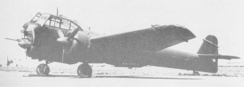
Built as an anti-submarine patrol aircraft for home defense, the Q1W1 was mentioned in a Japanese Navy delivery schedule directed to the manufacturer that was captured in 1944 and received the allied code name ‘Lorna’. It wasn’t spotted in action until 1945.
Kyushi built 153 of the Q1W1 Tokai during the war (allied codename Lorna).
Some Tokais were equipped with crude forms of radar and submarine detection gear.
Engines: 2 x Hitachi Tempu 31, 610 hp Wingspan: 52 ft 6 in AUW: 10,582 lb Max speed: 200 mph at 4396 ft Ceiling: 14,730 ft Range: 914 miles Armament: 1 x 20mm cannon, 1 x 7,7mm mg Bombload: 1100 lb Crew: 3
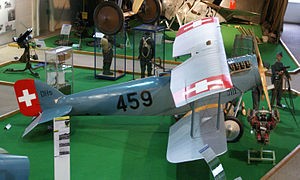
The Häfeli DH-5 was a two-seat reconnaissance aircraft designed by August Häfeli. It was a single-bay biplane of wood and fabric construction. The aircraft was powered by a 180 hp (134 kW) LFW I engine produced by the Swiss Locomotive and Machine Works.
Built by the aircraft department of the Federal Construction Works (Eidgenoessische Konstruktionswerkstaette, K + W) at Thun, Switzerland, test flying of the prototype commenced in March 1919 and 39 were ordered. Some aircraft were later modified with Handley Page slats.
A second batch of 20 aircraft were powered by a 200 hp (149 kW) LFW II engine. A further batch of 20 aircraft designated the DH-5A used the LFW III engine.
The DH-5 entered service in 1922 with the Swiss Air Force and was not withdrawn from service until 1940.
Variants
DH-5 Initial production version with either the LFW I or LFW II engine.
DH-5A Version with a 220 hp (164 kw) LFW III engines, survivors were modified at Thun in 1932 with Handley Page slats and changes to allow crew to wear parachutes.
DH-5X Trials aircraft powered by a Hispano-Suiza HS-42 (8Fb) engine imported from France. The aircraft was not ordered into production due lack of availability of the engines and the DH-5X crashed in 1933.
DH-5A Engine: 1 × LFW III, 220 hp (164 kW) Wingspan: 39 ft 4½ in (12 m) Wing area: 338 ft² (31.40 m²) Length: 24 ft 11¼ in (7.60 m) Height: 10 ft 2 in (3.10 m) Empty weight: 1,894 lb (859 kg) Max takeoff weight: 2,802 lb (1271 kg) Maximum speed: 112 mph (180 km/h) Range: 298 miles (480 km) Service ceiling: 18,375 ft (5600 m) Armament: one fixed forward-facing machine-gun one pivoted machine-gin in the rear cockpit Crew: two
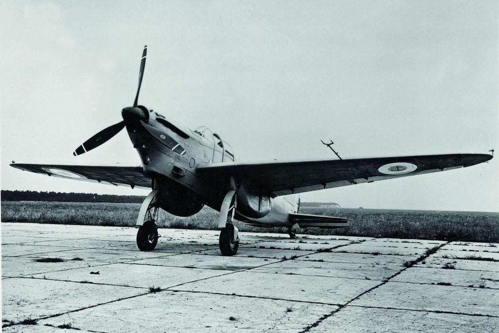
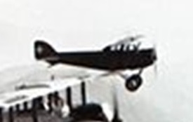
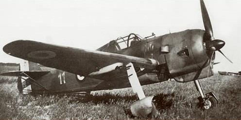
Dutch single seat fighter aircraft. The NV Koolhoven Vliegtuigen of Waalhaven, near Rotterdam, built the prototype F.K.58 within two months of completion of the design, and it flew for the first time on July 17, 1938, bearing the civil registration PH ATO. Designed by Dr Erich Schatzki, formerly of Fokker, to meet a French requirement, the F.K.58 had plywood covered wooden wings and fixed tail surfaces; a metal and fabric-covered steel tube fuselage; and metal framed fabric covered wing and tail control surfaces. A total of 450 litres (99 Imperial gallons) of fuel was carried internally, and the 1080 hp Hispano Suiza 14Aa 14 cylinder two row radial engine gave it a top speed of 483 km/h (300 mph). This prototype was demonstrated to the French authorities at the Centre d’Essais du Materiel Aeden at Villacoublay on October 10, 1938, and an order for 50 aircraft followed in January 1939. Intended for use by the Armee de l’Air in French Indo China, they were to be powered by, 1030 hp GnomeRhone 14N39 14 cylinder radials and designated F.K.58A. Deliveries began in mid June 1939, and 17 were delivered within the next three months, of which the first four retained the Hispano Suiza powerplant, the other 13 being F.K.58As. However, due to inadequate production facilities, the small Koolhoven factory was not able to complete the French order. The construction of 10 French F.K.58As was sub contracted to SABCA in Belgium, but although the airframes had been completed when Germany invaded that country in 1940, their Gnome Rhone engines had not been delivered from France. Following the first flight of a second Hispano powered prototype (PH AVA) on February 14, 1939, the Netherlands government in the following month ordered 36 F.K.58s, to be powered by 1080 hp Bristol Taurus III engines; but here again engine supply problems intervened, and Koolhoven was unable to complete any of the order for the Luchtvaartafdeling (Dutch air force). The production line and the second prototype were destroyed in a Luftwaffe air attack, the first prototype having already been lost in a crash in January 1940. Thus the only operational F.K.58s were those supplied to the Armee de l’Air. Armed with four 7.5 mm (0.29 in) FN Browning machine guns, in two underwing fairings outboard of the main undercarriage legs, most of them were deployed by patrouilles de protection in May 1940, in defence of such towns as Aulnat, Caen, Clermont Ferrand, Cognac and La Rochelle. For a short time, they were among the Luftwaffe’s most cosmopolitan opponents, for these Dutch fighters with French engines and Belgian guns were often flown by Polish pilots.
F.K.58A Span: 10.97 m (36 ft) Length: 8.68 m (28 ft 51 in) Gross weight: 2750 kg (6065 lb) Maximum speed: 475 km/h (295 mph).
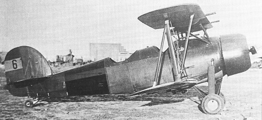
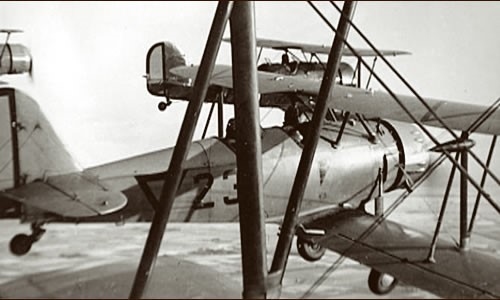
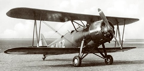
This two seat biplane had tandem open cockpits, with dual controls; it was armed with two 7.7 mm (0.303 in) for¬ward firing machine guns in the upper wing, a third movable 7.7 mm (0.303 in) gun in the rear cockpit, and provision for under¬fuselage bomb racks. A vertical camera was mounted in the floor of the rear cockpit. Usual powerplant was a 350 hp Armstrong Siddeley Cheetah IX radial engine, but some F.K.51s had 270 hp Cheetah V, 450 hp Pratt & Whitney Wasp, or (those for Spain) 400 hp Armstrong Siddeley Jaguar engines; the F.K.51 bis (for Spain) had a 450 hp Wright Whirlwind.
The LVA (Dutch army air service) ordered 53 in 1937, later increasing its order. In all, some 130 140 F.K.51s were built, of which 28 F.K.51/51bis were supplied to Spain during the civil war. When Holland was invaded in May 1940, the 2nd Air Regiment possessed 16 observation F.K.51s. Others were used by the Dutch East Indies army air service for reconnaissance and coastal/maritime patrol during 1941 42.
The FK.51 basic trainer first flew in May 1935. The type was ordered for the Dutch and Netherlands East Indian air forces. With a more powerful engine the type offered a combination of advanced training and limited combat capabilities, and during 1936 was ordered to the extent of 28 aircraft by the Republicans. These were delivered as 11 FK.51 aircraft with the 298-kW (400-hp) Armstrong Siddeley Jaguar VA radial and 17 FK.51bis aircraft with the 336-kW (450-hp) Wright R-975-E radial: some were used as night-flying trainers, but most served as night-fighters and reconnaissance aircraft with two fixed and one trainable machine-guns.
FK.51 Span: 9m (29ft 6.25 in). Length: 7.85m (25 ft 9in). Engine: 1 x Armstrong Siddeley Jaguar VA, 298kW (400 hp). Armament: provision for 3 x 7.7-mm (0.303-in) mg. Max T/O weight: 1450kg (3,197 lb). Max speed: 155 mph at 7,545ft. Operational range: 513 miles.