Waco F series / INF / KNF / MNF / RNF / PCF / PBF / QCF / UBF / UMF / UPF-7 / PT-14 / YMF / ZK-7 / ZPF / XJW-1 / YPF / QNF / CPF / DPF / EPF / VPF

INF

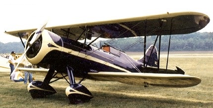
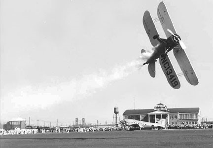
The Waco ‘F’ series of biplanes supplanted and then replaced the earlier ‘O’ series of 1927/33. The ‘F’ series had an airframe which was smaller and about 450 pounds (200 kg) lighter than the ‘O’ series, while continuing to provide accommodation for three persons in tandem open cockpits. A similar performance to the earlier model was obtained on the power of smaller and more economical engines.

The initial models were the INF (125 hp / 93 kW Kinner engine) with around 50 built, KNF (100 hp / 75 kW Kinner, about 20 built, ATC 313, at $3,630) and the RNF (110 hp / 82 kW Warner Scarab, nearly 150 built), all of which had externally braced tailwheel undercarriages. Many further sub-models followed with more powerful engines of up to 225 hp / 168 kW. The most powerful in the range was the ZPF of 1936/37, intended for executive use.

Waco KNF NX653N

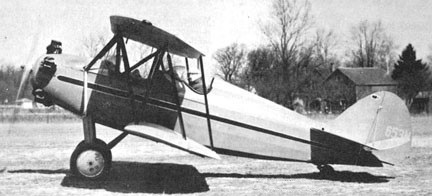
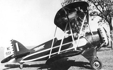
Only four 1931 MNF’s (ATC 393) were built; NC11213, NC11222, NC11239 and NC11246, priced at $4,475.

MNF

Al Menasco used the MNF to help promote his engines. A Heywood air-operated starter, caster action tail wheel, compass, navigation lights, first-aid kit and fire extinguisher were standard equipment on the MNF. NC11213 has the optional, Hamilton Standard ground adjustable prop. Brakes were optional.

The first QCF was finished on May 12, 1931. Thirty-one were built in 1932.

QCF-2

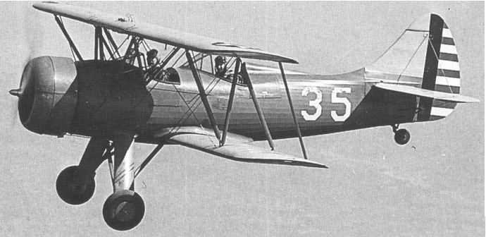
The ‘F’ series was popular with private owner pilots for sporting and other uses and continued in production through the late 1930s. The tandem cockpit UPF-7 was adopted by the Civilian Pilot Training Program and continued in production until 1942 by which time over 600 had been built.

One EPF-6 was built in 1936 and test-flown.

The 1936 VPF-6 was similar to the VPF-7 but with narrower landing gear and smaller wing cut-out. It was advertised as available, but none was produced. The 1937 VPF-7 (ATC 642) was the export version of the UPF-7. Priced at $9,500, six went to Guatemala, all of which returned to the US in 1959.

Waco VPF-7 NC78435
Waco XJW-1 9522

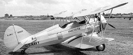
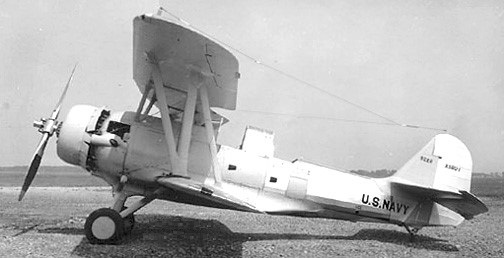
Two, 9521/9522, XJW-1 of 1934 were a USN version of the UBF as hook-up trainer and mail shuttle for the dirigible Macon.

Waco XJW-1 9522

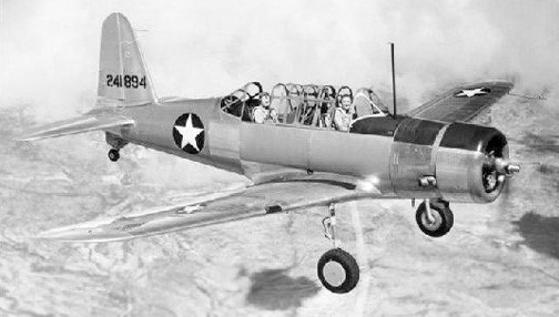
In 1937 Waco introduced its Model UPF-7 as an open-cockpit biplane with a 164-kW (220-hp) Continental W-670-K radial engine and seating for two or three. The type was intended for training and sport use. A single example was evaluated by the USAAC as a primary trainer during 1939 with the designation XPT-14.

Waco XPT-14 39-702

The 1939 XPT-14 39-702 crashed in testing on 11 October 1939.

Then followed 13 YPT-14 service trials aircraft, which were later re-designated PT-14.

Waco YPT-14

A single civil 1937 Model UPF-7 (ATC 642) was impressed in 1941 with the designation PT-14A. However, another 600 aircraft of the same basic type were ordered, priced at $9,500, with three engine types for the Civilian Pilot Training Program that undertook pilot training at educational institutions to provide a pool of trained pilots in the event of war. Another 31 similar aircraft were bought by the Civil Aeronautics Authority for its own flying unit, and 14 to the USAAF as YPT-14.

Waco UPF-7 1941

One QNF model was built. It flew, but presented nose-heaviness problems.

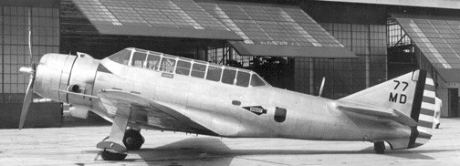
The three place YPF-6 and YPF-7 OF 1935 (ATC 586) featured a sliding canopy and unit price of $8,395. Five were built as YPF-6 (NC15700, NC15606, NC15711, NC16579, NC17470) and three re-designated in 1937 as YPF-7 (NC17710, NC17715, NC20907).

Waco YPF-6 NC16579
Waco YPF-7

Three ZPF-6 (ATC 586) were built in 1936, NC15707, NC16579, and NC17470, featuring a sliding canopy. The price was $7,385.

Two ZPF-7 were built in 1938, NC17710 and NC17715.

Waco ZPF-7 N29962

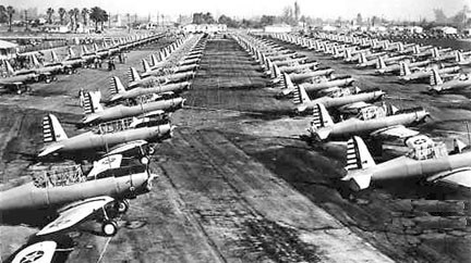
Approximately 600 came out of the Troy, Ohio factory between 1937 and 1942.

The WACO Aircraft Company of Ohio Inc had built three replicas by December 2011, which they designated MF.

Military operators

The Guatemalan Air Force received at least 1 Waco YMF-7 in 1934, which was still in airworthy condition in 1998.

The United States Army Air Corps adopted the UPF-7 as the PT-14, with one XPT-14 and 13 YPT-14s being purchased, with an additional UPF-7 impressed in 1942 as a PT-14A. Some were operated by the United States Navy.

PT-14
Waco CPF of Brazilian navy

The 1932 PBF (ATC 491) was priced at $4,415. Basically the same as PCF with modified ‘B’ wings. Four were built; NC13029, NC13049, NC13428, and NC13446.

Waco PBF NC13029

Three 1931 PCF (ATC 453) were built; NC11476, NC11483, and NS12439, priced at $4,415. The PCF-2
(Certified ATC#473 2 October 1931) featured a new cross-braced undercarriage.

Waco PCF NS12439

177 1930 Waco RNF were built (ATC 311, and 2-255 and 2-311) for weight changes. They were priced at $4,195-4,320, or $4,450 with an optional 125hp Warner engine.

Waco RNF NC853V
Waco UBF NC155Y

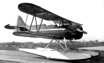
Priced at $5,025, about 11 1932 Waco UBF and UBF-2 (ATC 473) were built, of which 2 went to the USN as XJW-1 dirigible “skyhooks”, and one was fitted with EDO floats in 1933; NC13074.

Waco UBF-2 NC13419

Eighteen of the 1934 UMF-3 and -5 (ATC 546) were built at $6,530, of which 4 went to Guatemala, and 3 to the Cuban Navy. They were the forerunner of the UPF-7.

Waco UMF-3 NC14041

The YMF-3 (ATC 542) of 1934 was powered by a 225hp Jacobs L-4. Powered by a 245hp Jacobs L-4, the YMF-5 appeared in 1935 for $6,795. Eighteen were built.

The design was revived around.1990 by Classic Aircraft Corp of Lansing MI as the YMF-5 Super.

Waco YMF-5 NC14067

Considerable numbers of ‘F’ series biplanes, both original and newly built, remained in service in mid-2009.

Gallery

Variants:

CPF
1935 (ATC 583)
Engine: Wright R-760, 250hp (186 kW)
Wingspan: 30’0″
Length: 23’2″
Usefull load: 925 lb
Max speed: 150 mph
Cruise speed: 135 mph
Stall: 48 mph
Range: 400 mi
Price: $8,775.
Seats: 2-3
redesignated DPF

DPF-6
1936
Engine: Wright R-760, 285 hp (213 kW)
Was CPF-6

DPF-7
1936
Engine: Wright R-760, 285 hp (213 kW)
Seats: 3
Was CPF-7

EPF-6
Engine: Wright R-760, 320 hp (239 kW)
Seats: 3
1 built.

INF
Certified ATC#345 2 August 1930
Engine: Kinner B-5, 125 hp (93 kW)
Span: 29 ft 7 in (9.1 m)
Length: 20 ft 10 in (7 m)
Height: 8 ft 5 in (2.5 m)
Wing area: 244 sq ft (22.7 sq m)
Empty weight: 1870 lb (848 kg)
Loaded weight: 2650 lb (1202 kg)
Maximum speed: 128 mph (206 km/h)
Cruise speed: 96 mph
Stall: 40 mph
Range: 370 mi
Seats: 3
Price: $4,110
50 built

KNF
Certified ATC#313 12 April 1930
Engine: Kinner K-5, 100 hp (75 kW)
Wingspan: 29’7″
Length: 21’4″
Useful load: 776 lb
Max speed: 100 mph
Cruise speed: 85 mph
Stall: 40 mph
Range: 430 mi
Seats: 3
20 built

MNF
Engine: Menasco C-4 Pirate, 125 hp / 93 kW
Wing span: 27′ 5″
Length: 22′ 0″
Gross weight: 1900 lb
Useful load: 734 lb
Max speed: 118 mph
Cruise: 99 mph
Stall: 35 mph
Range: 365 mi
Seats: 3
4 built

QNF
Engine: Continental A-70, 165 hp / 123 kW
Max speed: 119 mph
Cruise speed: 104 mph
Seats: 3
1 built

RNF
Certified ATC#311
7 April 1930
Engine: Warner Scarab, 110 hp (82 kW)
Wingspan: 30’0″
Length: 20’10”
Useful load: 757 lb
Max speed: 112 mph
Cruise speed: 95 mph
Stall: 35 mph
Range: 400 mi
Seats: 3
177 built

1931 RNF

PBF
Engine: Jacobs LA-1, 170 hp (127 kW)
Wingspan: 29’7″
Length: 20’10”
Useful load: 956 lb
Max speed: 120 mph
Cruise speed: 102 mph
Stall: 42 mph
Range: 390 mi
Seats: 3

PCF
Engine: Jacobs LA-1, 170 hp (127 kW)
Wingspan: 29’7″
Length: 20’10”
Useful load: 972 lb
Max speed: 119 mph
Cruise speed: 101 mph
Stall: 42 mph
Range: 430 mi
Seats: 3
3 built

PCF-2
Certified ATC#473 2 October 1931
Engine: Jacobs LA-1, 170 hp (127 kW)
new cross-braced undercarriage

QCF
QCF-2 Certified ATC#416 9 April 1931
Engine: Continental A70, 165 hp (123 kW)
Wingspan: 29’7″
Length: 20’4″
Useful load: 864 lb
Top speed: 125 mph
Cruise: 108mph
Stall: 45 mph
Range: 430 mi
Seats: 3
31 built
Prototype NC11241

UBF / UBF-2 / XJW-1
Engine: Continental R-670, 210 hp (157 kW)
Wingspan: 29’6″
Length: 20’9″
Useful load: 920 lb
Max speed: 132 mph
Cruise speed: 116 mph
Stall: 42 mph
Range: 400 mi
Seats: 3
Two UBF designated XJW-1 were used by the US Navy as hook-up trainers for the Curtiss F9C Sparrowhawk airship-borne fighters.
Around 11 built

1932 UBF

UMF / UMF-3 / UMF-5
Engine: Continental R-670A, 210 hp (157 kW)
Wingspan: 30’0″
Length: 23’2″
Useful load: 1015 lb
Max speed: 143 mph
Cruise: 128 mph
Stall: 47 mph
Range: 460 mi
Seats: 3
longer wider fuselage and larger vertical fin
18 built

YMF-3
Engine: Jacobs L-4, 225 hp (168 kW)
Wingspan: 30’0″
Length: 23’4″
Useful load: 960 lb
Max speed: 147 mph
Cruise speed: 129 mph
Stall: 47 mph
Range: 420 mi
Seats: 3

YMF-5
Engine: Jacobs L-4, 245 hp (183 kW)
Wingspan: 30’0″
Length: 23’4″
Useful load: 890 lb
Max speed: 145 mph
Cruise speed: 129 mph
Stall: 47 mph
Range: 430 mi
Seats: 3

YPF-6 / YPF-7
Engine: Jacobs L-4, 225 hp (168 kW)
Wingspan: 30’0″
Length: 23’4″
Useful load: 975 lb
Max speed: 150 mph
Cruise speed: 135 mph
Stall: 50 mph
Range: 405 mi
8 built

VPF-6 / VPF-7
Engine: Continental W-670, 240 hp (179 kW)
Wingspan: 30’0″
Length: 23’6″
Useful load: 770 lb
Max speed: 133 mph
Cruise speed: 117 mph
Stall: 50 mph
Range: 370 mi
Seats: 2-3
6 VPF-7 built

YPF

ZPF-6
Engine: Jacobs L-5, 285 hp (213 kW)
Wingspan: 30’0″
Length: 23’7″
Useful load: 952 lb
Max speed: 156 mph
Cruise speed: 142 mph
Stall: 52 mph
Range: 420 mi
Seats: 2-3

1936 ZPF-6

ZPF-7
Engine: Jacobs L-5, 285 hp (213 kW)
Wingspan: 30’0″
Length: 23’6″
Seats: 3

Waco UPF-6
Engine: Continental R-670, 210 hp (157 kW)
Seats: 2-3
Prototype for UPF-7

UPF-7 / PT-14
tandem training version with wider-track undercarriage (USAAC)
Engine: l x Continental R-670-3 or W-670-6A, 164kW (220 hp) or Continental R-670-6, 220 hp
Wingspan: 30 ft 0 in (9.14 m)
Wing area: 244 sq.ft (22.67 sq.m)
Length: 23 ft 1 in (7.04 m)
Height: 8 ft 5 in (2.57 m)
Max TO weight: 2,650 lb (1202.02 kg)
Empty weight: 1,870 lb (848.22 kg)
Maximum speed: 128 mph (207 km/h)
Cruise speed: 114 mph (185 km/h)
Stall: 50 mph
Range: 400 miles (644 km)
Service ceiling: 14,800 ft (4,511 m)
Armament: none
Seats: 2-3
14 became YPT-14 trainers 40-014 – 40-026
over 600 built

Waco CG-4A Hadrian / LRW-1 / XLRN-1 / General Aircraft Corp CG-4A

Hadrian

During 1942 the U.S. Navy let contracts for the development of several amphibious transport gliders. At the same lime as the requirement for a twelve seat glider was issued, the US Navy ordered a small number of Waco CG 4A (Hadrian) gliders under the designation LRW 1. At least thirteen Waco LRW-1s were delivered (BuAer Nos. 37639 481 44319, and 69990 1), and the Naval Aircraft Factory modified two further CG 4As under the designation XLRN 1 (BuAer Nos. 36431 2).

Because military planners did not want to divert scarce strategic resources and aircraft workers from powered aircraft production to build gliders, the CG-4A was built by hundreds of subcontractors with experience in woodworking, including employees of furniture companies. The only large production facility was Ford Motor Company’s wooden station wagon plant. The CG-4A was a front-loading glider de¬signed to carry a pilot, co-pilot and 13 fully equipped glider infantrymen or an equivalent load of equipment or munitions.

On the Sunday afternoon of August 1, 1943, St. Louis aircraft manufacturer William B. Robertson was hosting the first public demonstration of a new Waco CG-4 glider, built under sub-contract by his company. As a crowd of spectators watched at the Lambert St. Louis Airport, Mayor William Becker, Robertson, and other St. Louis luminaries boarded the glider that was towed along by a transport plane for a flight over the city. Immediately after the release of the towing cable, the right wing of the glider broke off, and it plummeted from an altitude of 1,500 feet, killing all ten persons on board.

August 1, 1943 demonstration for a new aircraft. As soon as it took off, its right wing broke, and all ten passengers were killed. This is the group pictured before takeoff.

Including the two pilots in the hinged nose, it could carry 15 fully armed troops or a jeep with its crew, or an Army 75 mm howitzer with crew and ammunition. It could carry a total military load of around 3,500 lb and could land in a field 660 feet by 200 feet surrounded by 50 feet obstacles at a loaded stalling speed of 50-60 mph.
The fuselage of the Hadrian was 6 feet 5 inches wide and made of a steel tubular framework covered with fabric on wooden formers with a wooden floor. The wingspan was 83 feet 8 inches and the wings and tail unit were made of wood with a plywood and fabric covering. The training undercarriage consisted of independent wheels, with shock absorbers and hydraulic brakes. The operational undercarriage could be jettisoned by parachute and was a simple cross axle with brake-less wheels. The glider then landed on skids.

Operation Husky, the Allied invasion of Sicily beginning 10 July 1943, involved 400 Dakota C-47 transport aircraft and 170 Waco CG-4A cargo gliders. The operation verged on failure. Ninety-seven of the British and US gliders released from their towropes too early plunged into the sea, and another 24 were reported missing: only 12 of the gliders, all British, landed in the target zone. Then strong anti-aircraft fire confused the paratroops in the Dakotas, so they jumped too soon and were scattered over almost 60 miles. Six of the Dakotas were shot down, and only 73 British paratroops reached their target, the Ponte Grande bridge.

In mid-June 1943, for the first time, a Dakota FD900 of the RAF Transport Command landed in Prestwick, Scotland, the end of the North Atlantic route, towing a glider. The two planes had taken off together twenty-four hours earlier from Dorval (Montreal). The glider – a Waco CG-4A Hadrian – had been built in a New York piano factory. It carried a full load of urgently needed vaccine and radio and engine parts for the Soviet Union. The pilots, Sqn.Ldr. Seys and Sqn.Ldr. Gobeil: ‘We could not take our eyes off the Dakota and the tow rope, which was especially difficult in clouds or at night. We had to stay the whole time in the same position in relation to the towplane, which kept disappearing from our field of vision. Thank God we had radio contact with our Dakota. Unfortunately, there was no heating in the glider, so our teeth chattered with cold during the night or during prolonged flight through cloud, whereas sunshine changed our cockpit into a hothouse’.

Several hundred CG-4A gliders were built in 1945 with a paper composition floor rather than the reinforced plywood box floor. The glider could carry 13 infantrymen or a Jeep. Because of the floor, a trailer or howitzer could not be carried. The floor was reinforced at the Jeep wheel locations but not reinforced where the trailer or howitzer wheels would normally be positioned.

WACO CG-4A

It was named Hadrian when in service with the British forces, and was the only American built troop-carrying glider to be used by the allied forces in the airborne invasions of Sicily and France.

Ford produced the CG-4A. Approximately 14,000 were built.

Waco CG-13 / NLB

CG-13A

The Waco CG-13 was an American military transport glider aircraft developed during World War II. Wright Field Glider Branch realized a need for a glider larger than the CG-4A and requested designs. The response by several companies produced designs for five larger gliders. One of these designs was the XCG-13 by Waco Aircraft Company of Troy, Ohio.

The XCG-13 (Waco designation NLB) contract was for a 30-place design with an 8,000 lb (3,600 kg) useful load capacity to fly 174 mph (280 km/h) at an altitude of 12,000 feet (3,700 m) altitude. Flight testing of the prototype was performed at Clinton County Army Air Field and the type was approved on 10 March 1943. Testing found that a tricycle landing gear should be used, and that a hydraulic system be incorporated to open the top-hinged nose opening. These features were incorporated into the second XCG-13.

XCG-13

Ford Motor Company at Kingsford, Michigan and Northwestern Aeronautical at St. Paul, Minnesota built YCG-13 models and were given contracts to build the production CG-13A. WACO was not given a production contract. Northwestern Aeronautical built 49 production articles. Ford built 48 as 30 place and 37 as 42 place by adding a bench down the center of the cargo section. Between the two companies, 268 contracted articles were canceled in favor of producing more CG-4A gliders after 135 CG-13 were built.

The CG-13A glider maximum useful load was 10,200 lb (4,600 kg). The 79 mph (127 km/h) stall speed was 19 mph higher than specified. One CG-13A was flown in combat in the Appari Mission in the Philippines. The CG-13A gliders were not flown in combat in Europe but were used as transports in England and France.

Waco CG-13 towed by a Douglas C-54A

CG-13A
Wingspan: 85 ft 8 in (26.11 m)
Length: 54 ft 4 in (16.56 m)
Height: 20 ft 3 in (6.17 m)
Wing area: 873 ft² (81.10 m²)
Empty weight: 8,700 lb (3,946 kg)
Loaded weight: 18,900 (8,572 kg)
Useful load: 10,200 lb (4,626 kg)
Maximum speed: 165 knots (190 mph, 306 km/h) (maximum towing speed)
Stall speed: 79 mph (127 km/h)
Wing loading: 21.65 lb/ft² (105.7 kg/m²)
Crew: 2 pilots
Capacity: 30 or 42 troops (including flight crew)

Waco CG-3

CG-3A

The CG-3A was the United States Army Air Force’s first production troop-carrying glider. First flown in early February 1942, 300 CG-3A 9-place gliders were initially ordered, but 200 of these were cancelled. A few of the 100 built by Commonwealth Aircraft (formerly Rearwin Aircraft) were used as trainers for the improved CG-4A, but most remained in their shipping crates in storage.

The production CG-3A was developed from the experimental XCG-3 which was the only one built by Waco and given Army Air Forces Serial No. 41-29617. Unit cost: approx $24,000.

The CG-3A became obsolete with the development of the much improved Waco designed CG-4A 15-place glider with its alternate load of military equipment. The CG-3A did not see any combat and several were used in limited training roles.

Variants
XCG-3
Prototype 8-seat glider. One built 1942.

CG-3A
Production 9-seat glider. 100 built by Commonwealth Aircraft.

Specifications:
CG-3A
Wingspan: 73 ft 1 in (22.28 m)
Length: 43 ft 4 in (13.21 m)
Empty weight: 2,044 lb (927 kg)
Max takeoff weight: 4,400 lb (1,996 kg)
Maximum speed: 120 mph (193 km/h; 104 kn) (under tow)
Normal tow speed: 100 mph (87 kn; 161 km/h)
Minimum control speed: 38 mph (33 kn; 61 km/h)
Crew: 2
Capacity: 7 troops

Vultee V-72 Vengence / A-31 / A-35

Vultee V-85 First prototype

The Vultee A-31 Vengeance dive-bomber was designed led by Richard Palmer to meet French air force requirements.

The RA-31 (Model V-72) export model (as prototype V-85) first flew on 30 March 1941 piloted by Vance Breese. There was a second prototype with twin tails, but pilot Vance Breese refused to fly after finding dangerous tendencies during taxi tests, and it was quickly modified with a single tail. It first flew (as Vengeance I) on 30 November 1941, piloted by Moye Stephens.

400 went to the RAF as Vengeance I/IA, subcontracted to Northrop Corp for production during 1941-42, of which 99 went to the RAAF, plus 300 to the USAAF as RA-31 in a special Restricted classification (41-30848 – 41-31047, and 41-31048 – 41-31147), the last batch of 100 built by Northrop; 300 to RAF as Vengeance II, plus 243 to USAAF with type re-designation as model 85 in 1942; 100 as Vengeance III, becoming Army A-31C, with subsequent production as A-35.

Vultee RA-31

The 1942 V-86 was a single place version of the A-31.

The XA-31A Model 85 of 1942 (42-35824) was a test-bed for the 3000hp P&W XR-4360 engine. It was re-designated XA-31B Model 86 for flight tests.

The A-31C of 1942 was t first production of the Vengeance III. One hundred were built; 41-30148 – 41-31147.

The XA-31C of 1942 was a test-bed for the 2200hp Wright R-3350 engine.

Five YA-31C were built in 1942 and went to Wright Field for testing of four-bladed props in the B-29 development program.

The A-35 Vengeance (Model 88) were A-31 for the USAAF, with similar data, but improved armament.

Vultee A-35A 41-31166

The 1942 A-35A were the second production of Vengeance III. Ninety-nine were built; 41-31148 – 42-31246.

781 A-35B of 1942 were built; 41-31247 – 41-31447, 42-94149 – 42-94548, and 42-101236 – 42-101465. Contradicting factory records show 831 A-35Bs built, with 562 going to the RAF and RAAF as Vengeance IV, and 29 to Brazil AF. (67 A-35A and -35B were supplied to the Free French, but it is unclear whether these were culled or a separate production.)

Vultee A-35B

All models were powered by Wright R-2600 Cyclone engine.

Gallery

V-72 A-31 Vengeance
Engine: 1600hp Wright GR-2600A
Wingspan: 48’0″
Length: 39’9″
Useful load: 3215 lb
Max speed: 275 mph
Cruise: 235 mph
Stall: 80 mph
Range: 500 mi
Ceiling: 22,300 ft
Seats: 2

A-35B / Vengeance IV
Engine: 1700hp R-2600
Wingspan: 48’0″
Length: 39’9″
Max speed: 279 mph
Cruise: 230 mph
Stall: 84 mph

Vultee P-48 Vanguard / P-61 Vanguard / P-66 / V-48

Vultee V-61 Prototype NX21755

The Vultee P-66, P-48, V-48/-61 Vanguard (Models 48, 61) incorporated design elements from the Hughes H-1 racer and detachable outer wing panels for storage.

Vultee V-61 Prototype NX21755

Designed by Dick Palmer as a company demonstrator, the V-48 NX21755 c/n 142 first flew on 9 September 1939, piloted by Vance Breese. The V-48 was powered by a P&W R-1830-S Twin Wasp with an extended propshaft in an elongated low-drag cowling. The original proposal included two rear-firing guns aimed with mirrors. The prototype, NX21755 c/n 142, was later re-designated V-61, then P-48X.

The 1940 P-48X was a redesign of the V-61 with a conventional R-1830-S1 engine because of cooling problems. First flown on 11 February 1940, piloted by Vance Breese, and it crash-landed on May 9 after colliding with a camera plane.

Vultee P-48X NX21755

The 1940 V-48C was the V48-X rebuilt and repowered with a R-1830-S2 engine for export to Sweden’s Flygvapen as the J.10. First flown on 6 September 1940, it was re-registered NX19999 c/n 501, and followed by one production prototype, NX28300 c/n 502.

Vultee V-48C / P-48C NX28300

One-hundred and forty-four were built for Sweden (42-6832 to 42-6975), but diverted to the RCAF, who in turn released 129 of them after the outbreak of WW2 as Lend-Lease to China as P-66, and so marked with US insignia. Of the total about 50 were impressed for Army stateside assignment, and 12 transferred to 23 Fighter Group in China.

Vultee P-66

V-48
Engine: P&W R-1830-S Twin Wasp
Wingspan: 35’10”
Length: 28’5″
Useful load: 2165 lb
Speed: 340 mph
Range: 850 mi
Seats: 1

Vultee BC-3 / 54 BT-13 / BT-15 Valiant / SNV / BC-51

The BC-3 (Model 51 aka BC-51) Army basic combat trainer first flew on 24 March 1939 (piloted by Eddie Allen). The only one built, 39-720, was tested by the Army, who purchased the test model for upgrading as BC-3, one of the only three BC classifications (the other two were North Americans).

Vultee BC-3 39-720

Following 1939 tests with the BC-3 variant with retractable landing gear and a 447-kW (600-hp) Pratt & Whitney R-1320-45 radial, the army opted for the lower-powered Model 54 with fixed landing gear. Designed by Richard Palmer, Walt Hite, and others, the initial contract called for 300 aircraft (40-810-1109).

Vultee BT-13

The 1939 V54 (Model 51D) was a retractable-gear export model demonstrator with a 600hp R-1340-S1 engine. The one prototype built, NX21753 c/n 140, first flew on 15 November 1939 piloted by Gil Clark), but crashed on 16 November 1939.

Vultee V-54 / 51D NX21753

The 1940 V54-A NX21754 c/n 141 was a faired, fixed gear, 450hp R-985-AN-1 powered prototype of the BT-13. It first flew on 28 July 1940.

Vultee V54-A NX21754

The BT-13s were followed by orders for no fewer than 6,407 BT-l3As and 1,125 BT-l3Bs with a 24- rather than 12-volt electrical system.

The 1940 BT-13A was powered by a 450hp R-985-AN-1 engine. Gear fairings were deleted in 1941. A total of 7,037 were built: 41-1211-1710, 41-9587-9979, 41-10410-11586, 41-21162-23161, 42-1164-1743, 42-42201-43257, and 42-88674-89573, plus 430 (41-09980-10409) to the USN and USCG as SNV-1, and 12 to the Peruvian AF.

Vultee BT-13A
Vultee 54 Peru export with fairings

The 1941 BT-13B featured a 24v electrical system. 1,125 were built (42-89574-90698, and 44-31511-32160), with the last batch of 650 transferred to USN as SNV-2. Totals of all models include Lend-Lease exports to China, France, Haiti, Indonesia, Israel, the Philippines, and South American nations.

Demand far outstripped engine supplies, however, and in 1941 the USAAF ordered the BT-15 variant with the 336-kW (450-hp) Wright R-975-11 radial, and production of this model totalled 1,263. (41-9980-10409, 42-1744-2063, and 42-41258-42200)

Vultee BT-15 42-41894

The US Navy procurement began with the 1940 US Navy SNV-1, the same as BT-13A. 1,125 (02983-03182, 05675-05874, and 12492-12991) (USN serials total 1,350, but is unexplained—perhaps includes a cancelled batch), with 2 (V222 and V223) to USCG, plus 450 (34135-34584) transferred from USAAF (44-31511-32160, et al) aircraft were retired soon after the war.

Vultee SNV-1 N56319

These were followed by 650 SNV-2s, equivalent to the BT-13B, in 1944. They were BT-13B transferred from the USAAF (44-31511-32010 became 52050-52549, and 32011-32160 became 44038-44187).

Circa 1950 of 3 Vultee BT-13s at Puente Sky Ranch

When production ceased in 1944, 11,537 had been built.

Gallery

BC-3 / Model 51 / BC-51
Engine: P&W R-1340-S3H1G Wasp, 600hp
Wingspan: 42’0″
Length: 28’10”
Useful load: 920 lb
Speed: 180 mph
Range: 725 mi
Seats: 2
Undercarriage: retractable

V54 / Model 51D
Engine: P&W R-1340-S3H1G Wasp, 600hp
Undercarriage: retractable

BT-13 Valiant / Model 54
Engine: 450hp P&W R-985-25
Wingspan: 42’2″
Length: 28’10”
Useful load: 1121 lb
Max speed: 166 mph
Cruise: 140 mph
Range: 515 mi
Ceiling: 16,500′
Seats: 2

BT-13A Valiant / SNV-1
two-seat basic trainer
Powerplant: l x Pratt & Whitney R-984-AN-1, 336kW (450 hp)
Span: 12.80m (42ft)
Length: 8.79m (28ft 10 in)
Max TO weight: 2039 kg (4,496 lb)
Max speed: 180 mph at sea level
Operational range: 725 miles
Armament: none

BT-15 Valiant
Engine: Wright R-975-11, 336-kW (450-hp)

Vultee V-11 / A-19

Vultee V-11 NX14999

The prototype Vultee V-11 Army attack bomber NX14999 c/n 28 first flew on 17 September 1935, piloted by T C Van Stone. It crashed on take-off for its second flight the next day, killing Van Stone and project engineer Duald L Blue.

Vultee V-11 NX14999

The second V11 prototype, but with 1800hp P&W R-2800 Double Wasp and three-blade prop, NX/NR/NC14980 c/n 29, first flew on 9 October 1935 as a demonstrator for the South America market.

Vultee V-11A NR14980

The second V11 prototype, built first as a V-11A, it was later modified as the fixed-gear V-11T for Pratt & Whitney’s use in engine testing, first flying on 21 January 1940.

Vultee V-11T NC14980

Ultimately refitted with 2000hp R-2800, it was destroyed in a crash on 20 March 1945.

The V-11G and -11GB were versions with a 1000hp Wright SGR-1820-G2 Cyclone. The V-11G was a two-seater, and -11GB sat three (pilot, bombardier, gunner) with a retractable ventral gun position. One was built as a company test hack on wheels (NX/NR17327) and seven with a 1200hp P&W R-1830-17 went to the USAAC in 1939 for field testing as YA-19 (38-549 to 38-555).

Vultee V-11GB Ventral gun station

China ordered 30 two-seat Vultee V-11Gs in 1937-38 and then more Vultee V-12s (a more powerful variant) which they were planning to assemble from kits (25 were finished)

At the end of June 1935, information reached Moscow about the new American Vultee V-11 attack and bomber aircraft. In a report to Defense Commissar Kliment Efremovich Voroshilov on the acquisition of aircraft production licenses in the United States, the chief of staff of the VVS RKKA VK Lavrov placed special emphasis on the excellent characteristics of the V-11 in terms of speed and range. In fairness compared to the obsolete R-5Sh and R-5SSS the approach was valid.

As a consequence, the Vultee V-11 was part of the purchase of production licenses approved by the Labor and Defense Committee (STO) on April 11, 1935.

On September 7, 1936, the Soviet foreign trade company “ Amtorg ” signed a contract with the American firm “ Airplane Development Corporation”, to which Vultee belonged at that time . The content of the negotiation stipulated the granting of a license to the Main Directorate of the Aeronautical Industry (GUAP) of the People’s Committee for Heavy Industry (NKTP) for the construction of the V-11 in two variants: V-11G as attack aircraft and V-11GB as a light bomber. This latest version incorporated a third member of the crew serving as navigator-bomber.

In 1937 two examples were received in flight condition and another two unarmed, which were thoroughly studied by the TsAGI and the NII VVS. The four -11GB were NR17328-17329 and 2 unregistered, along with some EDO sets to transform them into -11GBS seaplane and -11GBF floatplane attack bombers.

In the USSR in 1937

The North American counterpart delivered the plans with detailed engineering, the specifications, instructions and description of the processes, documentation on the jobs and the technological processes, as well as the technical data of the ground and flight tests of the model, as well as the obtained in tests in wind tunnels; resistance calculations and more than 300 photographs of details and aggregates. The purchase of several copies, parts and pieces was also considered to facilitate the start of series production. An interesting detail was the request from the USSR to modify all the schematics and plans of the model under the international metric system.

The Vultee firm delivered two fully assembled examples to be used as a basis for comparison, both with a Wright SR-1820-G2 engine and full armament and without a radio. The first, with number “ 32 ”, left the production workshops on December 22 , 1936 . It was planned to be sent to the USSR in January 1937, but the appearance of small defects delayed the decision. This first example took flight on January 31, 1937 and was tested by pilot SA Levanievsky on February 2 with the mechanic Chiechin. Levanievsky rated the aircraft positively in terms of maneuverability, stability and ease of flight.

The tests were carried out until mid-February 1937 and the chief of technical supply of the VVS Bazienkov and the director of the TsAGI Jarlamov participated as observers. It was flown from the Vultee factory airfield and from the military base in Long Beach. Tests were carried out over the ocean of weapons firing and bomb drops. The “ 32 ” was tested as an attack aircraft version and as a light bomber. A second specimen with number ” 33 ” flew for the first time on February 26. The Soviet delegation received the first issue in March and the second in April. Two other copies ” 34 ” and ” 35″ were delivered” in parts and without engine.

Upon arrival in the USSR the planes were studied in depth. The “ 33 ” plane was sent directly to the NII VVS to carry out the state tests, keeping the American equipment and weapons. In the first half of 1937 the V-11GB was studied in detail at the TsAGI and the NII VVS. The test pilot designated to lead the tests was Captain AK Dolgov, but the plane was flown by a large number of pilots, including the head of the institute NN Bazhenkov and the experienced test pilots Stefanovski, Fedrov, Niuxtikov.

The tests of the ” 33 ” contemplated the complete range, including its air combat simulation, completing a total of 70 flight hours. Test results were conflicting. On the one hand, the NII VVS concluded that due to its weapons and equipment capacity, the V-11 could be used as an attack and bomber aircraft. However, due to its speed and turnaround time, it was already obsolete. With a similarly underpowered engine, the Nieman R-10 bested the V-11 by 30 km/h and reached 5000 meters 5.6 minutes earlier. In the parameters of takeoff and landing characteristics, the R-10 was also superior.

The V-11’s armament was also considered obsolete. The rear firing point had a poor operating angle and did not guarantee the protection of the plane against the attack of the fighters. The absence of a lower turret (which was removed from the aircraft delivered to the USSR ) left all that area exposed to enemy attack. During simulated combats with I-16 Type 4 it was demonstrated that the V-11 was unable to escape before the attack of the fighters and to defend against their attack. Another conclusion established the absence of capacity to carry containers of chemical weapons (at that time in the USSR great importance was given to this type of armament). The bomb racks were not designed to allow the attachment of Soviet containers. Finally the Vultee V-11 was not prepared to work in the harsh Russian winter.

On the other hand, the Vultee V-11 showed the Soviet builders many new aspects. The construction technology, the materials used, many construction details and technological solutions were carefully studied and documented in order to introduce them into the productive process of the Soviet aeronautical industry.

High value was given to the comfort of the cockpit and the excellent visibility, the effective amortization system of the landing gear and brakes. The retraction system of the landing gear units was studied in detail. The measures taken to reduce the vibrations transmitted by the engine to the fuselage structure were highly valued.

The aircraft was easy to assemble and disassemble, and the designers provided easy access to all vital mechanisms and accessories for maintenance and repairs.

From the point of view of the flight, the stability in flight, the excellent work of all the mechanisms and the reliability of the engine were highly valued.

After evaluating the positive and negative aspects of the V-11G, it was decided to proceed to mass production of the model under the name BSh-1, its production being assigned to the OKB-1 led by S. A Kochierigin. In the issued documents it is clear that the fundamental reason was not to assess the possibilities of the model, but the possibility of becoming familiar with the new technological processes used in the construction of this aircraft. The production of the V-11G was considered to be the first step towards the development of a modern and effective bomber and attack aircraft for Soviet aviation.

Forty -11GB went to Turkey redesignated -11GBT, and 26 -11GB to Brazil in 1938-39 as -11GB2, the last of which was modified with EDO floats as 11GB2F for the Brazilian Navy, as also was prototype NX21719 in hopes of civil sales, which didn’t occur.

Vultee V-11GB2F

The three-place A-19 attack bomber from the V-11GB was all-metal except for the tail control surfaces. The YA-19 (Model V-11GB) first flew on 27 January 1939 and of the seven, three were converted from V-11G and repowered as XA-19 series.

Out of the five Vultee YA-19 (Pratt & Whitney Twin Wasp R-1830-17 radials) three-seat attack bombers delivered to the USAAF in 1939, three underwent engine changes to become the XA-19A (Lycoming); XA-19B (P&W Double Wasp R-2800-1) and XA-19C (P&W Twin Wasp R-1839-51).

The XA-19A served as a flying testbed for the 12-cylinder, liquid cooled XO-1230-1, with 1200 hp for take-off. To compensate for the increased side area and fuselage length (increased by 5in to 38ft 3in) the Gerald Vultee fin was altered to give more area. Despite the improved frontal area streamlining, the XA-19A improved the maximum speed by only 2 mph, to 232 mph. The span was 50 ft.

Vultee YA-19

The 1940 XA-19A (Model V-11) featured an enlarged, triangular fin and 1200hp Lycoming O-1230-1 engine. The one was converted from a YA-19 and first flew on 22 May 1940. It later became a XA-19C.

Vultee XA-19A

YA-19 38-550 was converted to the XA-19B in 1939, powered by an 1800hp P&W R-2800-1 engine.

Vultee XA-19C 38-555

Converted from XA-19A 38-555, the 1939 XA-19C 1939 was powered by a 1200hp P&W R-1830-1/-51.

The aircraft had limited combat success with the Chinese, and a Brazilian Vultee V-11 made an attack on a submarine, damaging itself in the process. Later developments would have a rear facing gunner at the back of the cockpit plus a rear-facing ventral gun position protruding from the bottom. Most were later used as high speed liaison and transport aircraft.

Gallery

Second V11 prototype
Engine: 1800hp P&W R-2800 Double Wasp
Prop: three-blade
Wingspan: 50’0″
Length: 37’6″
Useful load: 3450 lb
Max speed: 232 mph
Cruise speed: 213 mph
Stall: 68
Range: 1220 mi

V-11
Engine: 750hp Wright SGR-1820
Prop: 2 blade
Wingspan: 50’0″
Length: 37’6″
Useful load: 3265 lb
Max speed: 229 mph
Cruise speed: 207 mph
Stall: 68 mph
Range: 1225 mi
Ceiling: 28,000′
Seats: 2

Engine: Wright SR-1820-F53
Time to 20,000ft: 14 min
Service ceiling: 27,000 ft
Absolute ceiling: 29,000 ft
Cruise: 220 mph
Top speed: 265 mph
Seats: 2

YA-19 / V-11GB
Engine: P&W R-1830-17 Wasp, 1200hp
Wingspan: 50’0″
Length: 37’10”
Useful load: 3969 lb
Max speed: 230 mph
Cruise speed: 207 mph
Stall: 80 mph
Range: 1110-1385 mi
Ceiling: 24,400′

XA-19A / V-11
Engine: 1200hp Lycoming O-1230-1
Useful load: 3680 lb
Speed: 232 mph

XA-19B
Engine: P&W R-2800-1, 1800hp

XA-19C
Engine: P&W R-1830-1/-51, 1200hp

Vought SBU / V-142

Vought XSBU-1 9746

The Vought SBU was a scouting design modified from a two-place fighter. Exports to Argentina were designated V-142. The 1934 XSBU-1 prototype 9746 was rebuilt and modified from an XF3U-1.

Eighty-four SBU-1 were built in 1935: 9750-9833.

Vought SBU-1

Forty SBU-2 built in 1937 featured a modified engine; 0802-0841.

Vought SBU-2

SBU / V-142
Engine: 700hp P&W R-1535
Wingspan: 33’3″
Length: 27’10”
Useful load: 1739 lb
Max speed: 208 mph
Stall: 65 mph
Range: 902 mi
Ceiling: 24,400′
Seats: 2

Vought VE-7 Bluebird / Lewis & Vought VE-7

Vought VE-7 Bluebird

The two-place Lewis & Vought VE-7 Bluebird of 1917 was advertised post-WW1 as a sport and training plane. One prototype was built. The wings and tail of the prototype were located in a hangar after WW2, and rebuilt into Waterman Pusher).

Vought VE-7

The VE-7 was built in 1918 (The first production aircraft of Chance Vought) as an advanced military trainer, observer, and fighter. Fourteen went to the USAS including AS19898-19902 and AS40072 (One of two known to have been built at McCook Field). Reportedly four more were built by Springfield Co and possibly never assigned s/ns.) There were conversions to VE-7G, 7GS, and -7S.

The USN received twenty VE-7, A5661-5680, plus 39 built by NAF, A5942-5969, A5971, and A6011-6020.

Vought VE-7 Instrument panel

Forty of the 1921 VE-7F were built, A5912-5941, and A6021-6030, plus 29, A5943-5971, by NAF. They were powered by 180hp Wright E-3 engines.

In 1921 twenty-three VE-7, A5681-5700 were converted to VE-7G by NAF with 180hp Hispano E engines and one was modified, A5685, as a VE-7GF.

Vought VE-7G A-5692

NAF built nine VE-7H, A6436/6444, with 180hp Hispano E engines for the USN in 1924.

In 1925 forty VE-7S were built for the AAF plus eleven to the USN, A5942 and A6011-6020, as VE-7SF, and one, A5680, as VE-7S converted from a VE-7 by NAF.

Vought VE-7S mod from -7

A VE-7 was the first aircraft to fly from an aircraft carrier.

A scratch-built replica of the Bluebird was completed in early 2007 by volunteers of the Vought Aircraft Heritage Foundation.

VE-7 Bluebird prototype
Engine: 150hp Wright-Hispano A
Wingspan: 34’2″
Length: 24’6″
Useful load: 536 lb
Speed: 114 mph
Seats: 2

VE-7F
Engine: 180hp Wright E-3
Wingspan: 34’1″
Length: 24’5″
Speed: 119 mph
Ceiling: 19,200′

VE-7G
Engine: 180hp Hispano E

VE-7GF
Engine: 180hp Hispano E

VE-7H
Engine: 180hp Hispano E
Length: 31’1″
Speed: 110 mph
Ceiling: 14,800′

VE-7S
Engine: 180hp Hispano E
Length: 24’5″
Speed: 117 mph
Range: 290 mi
Ceiling: 15,000′
Seats: 1

VE-7SF
Engine: 180hp Hispano E
Length: 24’5″
Speed: 117 mph
Range: 290 mi
Ceiling: 15,000′
Seats: 1