Martin P5M Marlin / SP-5

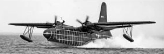
As a new US Navy patrol flying-boat, Martin developed the Model 237 design, combining the wing and upper hull of the Mariner with the new lower hull structure. A PBM-5 Mariner served as the prototype XP5M-1 which, when ordered into production, was given the name Marlin.

The modified hull of the XP5M-1 incorporated radar-directed nose and tail turrets, as well as a power-operated dorsal turret, and power was provided by two 2424kW Wright R-3350 radial engines.

This prototype flew for the first time on 30 May 1948, but it was not until two years later that the P5M-1 was ordered into production, the first of these series aircraft being flown on 22 June 1951.

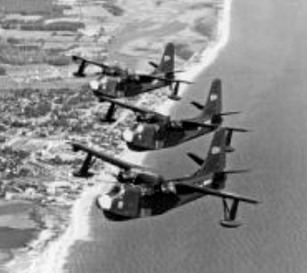
Initial deliveries, to US Navy Squadron VP-44, began on 23 April 1952 and the type remained in service until the mid-1960s.

Martin P5M-1

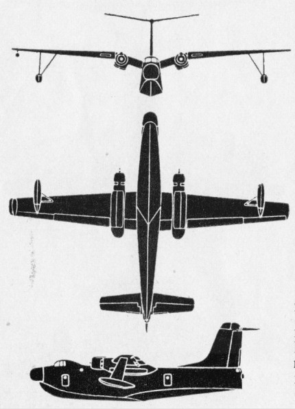
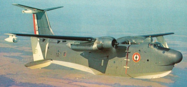
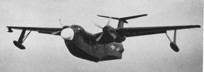
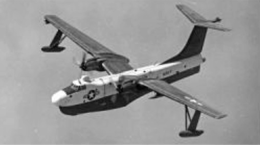
In addition to those operated by the US Navy, 12 of the later P5M-2 version were supplied to France under the American MAP for use by the Aeronavale in 1959. In the French Aeronavale, where they were used for maritime patrol out of Dakar, West Africa, until 1964, after which they were returned to the Navy. The P5M 2 Marlin could carry up to 8,000 lb (3,629 kg) of assorted weapons. The P5M-1 has a low mounted ” dihedral ” tailplane, different hull shape and lower-powered engines, compared to the P5M-2.

The first of 28 P5M-2 Marlins to undertake a modernisation program was delivered to the US Navy in 1959.

Martin aircraft production ceased December 20,1960 when the last P5M- 2 Marlin was handed over to U.S. Navy.

Claiming high operational costs, the Coast Guard turned over all of its P5Ms to the Navy in 1961. Lacking most military equipment, they were used as crew trainers as P5M-1T and P5M-2Ts.

In September 1962, when all American military forces adopted the tri-service designation scheme, the P5M-1 became the P-5A, the P5M-1S the SP-5A, the P5M-1T the TP-5A, the P5M-2 the P-5B, the P5M-2S and P5M-2T the PT-2B.

SP-5B / P5M2

In 1964, in an attempt to boost take-off power, one SP-3B was tested with a tail mounted 3000 lb.st Pratt & Whitney J60 turbojet engine. They were not adopted for service.

No Marlins went to the reserves. As they were retired, they were stored until sold as scrap. A Navy SP-5B of VP-40 made the last operational flight on 6 November 1967.

Model 270

The XP5M-1 prototype was later used (as the model 270) to test the 15:1 hull configuration for the P4M SeaMaster.

Gallery

P5M
Engines: 2 x Wright R-3350-32WA Turbo-Compound, 2573kW
Max take-off weight: 38555 kg / 85000 lb
Empty weight: 22900 kg / 50486 lb
Wingspan: 36.02 m / 118 ft 2 in
Length: 30.66 m / 100 ft 7 in
Wing area: 130.62 sq.m / 1405.98 sq ft
Max. speed: 404 km/h / 251 mph
Ceiling: 7300 m / 23950 ft
Range: 3300 km / 2051 miles
Armament: 3600kg of weapons
Crew: 11

P5M-2 Marlin
Naval patrol bomber flying boat
Engines: 2 x Wright R3350-32W Turbo-Cyclone, 3450 h.p
Wingspan: 118 ft. 2in (36.02 m)
Wing area: 1406.3 sq.ft
Length: 100 ft. 7in (30.66 m)
Height: 32 ft 8.5 in (9.97 m)
Empty weight: 50,485 lb
Max TO wt: 85,000 lb (38,555 kg).
Loaded weight: 73,055 lb
MTOW: 76,635 lb
Fuel capacity: 4410 gal
Max speed: 251 mph at SL
Ceiling: 22,400 ft
Normal range: 2050 mi
Max range: 3,600 miles
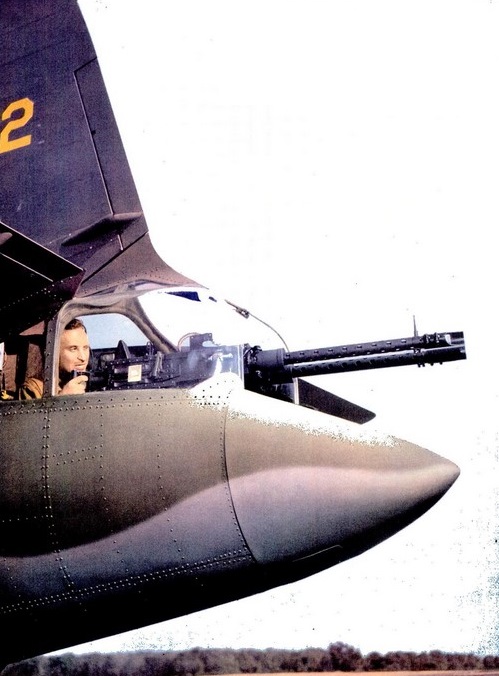
Armament: 2 x 20mm tail mounted guns
Bombload: 16,000 lb
Crew: 7

P5M-2 Marlin

Martin 162 PBM Mariner

The XPBM-1 prototype flying-boat patrol bomber was originally ordered by the US Navy in 1936. Before it was built, a quarter-size prototype (Model 162A) was constructed and flown. The full-size aircraft was flown for the first time in February 1939.

The production PBM-1 – fitted with two 1,192 kW Wright R-2600-6 radial engines, a dihedral tail and retractable wingtip floats – was ordered in 1938 and 20 of these went into Navy service in 1941. A single XPBM-2 was ordered at the same time as a long-range version specially strengthened for catapult take-off.
The PBM-3, with two 1,267kW Wright R-2600-12 engines, was ordered in quantity in 1940 and deliveries began in 1942. In this version the crew was increased from seven to nine, the armament was revised and the fuel capacity increased. The retractable wingtip floats of the PBM-1 were replaced by fixed floats. In 1942 the PBM-3 was adopted also as a naval transport carrying 20 passengers or 3,629-4,082kg of cargo (PBM-3R). Twenty-six PBM-3B patrol bombers were also used by RAF Coastal Command, delivered under Lend-Lease. At the end of the war a specialised anti-submarine version was also developed as the PBM-3S.

PBM-5A

The final two production versions of the Mariner were the PBM-5 and PBM-5A, powered by 1,565kW R-2800-22 and R-2800-34 engines respectively. The last PBM-5A was delivered to the US Navy in April 1949. This version was basically an amphibious version of the PBM-5 and ended its career as a general utility aircraft.

PBM-5A Mariner

630 PBM-5 flying boats were built, followed by 36 PBM-5A amphibians, used for air-sea rescue duties, primarily by the U.S.C.G.

In 1963 the US Navy tested vertical floats designed by General Dynamics/Convair, on a PBM-5.

These made the seaplane a stable working platform for anti-submarine warfare with little motion from 4-5 ft waves.

Gallery

Engines: 2 x Wright R-2800A-5B, 1250kW
Max take-off weight: 25400 kg / 55998 lb
Empty weight: 14660 kg / 32320 lb
Wingspan: 36.0 m / 118 ft 1 in
Length: 34.4 m / 112 ft 10 in
Height: 8.4 m / 27 ft 7 in
Wing area: 130.0 sq.m / 1399.31 sq ft
Max. speed: 325 km/h / 202 mph
Cruise speed: 240 km/h / 149 mph
Ceiling: 6150 m / 20200 ft
Armament: 8 x 12.7mm machine-guns, 2000kg of bombs
Crew: 7

PBM-5A Mariner
Air-sea rescue amphibian
Engines: 2 x Pratt & Whitney R2800-34, 2,100 h.p.
Wingspan: 118ft
Length: 79ft. 10in
Loaded weight: 60,300 lb
Max speed: over 200 m.p.h.
Ceiling: 20,200 ft.
Max range: 2,900 miles at 143 m.p.h.
Armament: (when fitted) 8x.50 in machine-guns
Bombload: 4,000 lb

Martin PBM 3 D Mariner
Engines: 2 x Wright R-2600-22 Cyclone, 1874 hp
Length: 79.823 ft / 24.33 m
Height: 27.493 ft / 8.38 m
Wingspan: 118.012 ft / 35.97 m
Wing area: 1407.931 sq.ft / 130.8 sq.m
Max take off weight: 58009.1 lb / 26308.0 kg
Weight empty: 33180.8 lb / 15048.0 kg
Max. speed: 184 kts / 340 km/h
Service ceiling: 19800 ft / 6035 m
Wing load: 41.21 lb/sq.ft / 201.00 kg/sq.m
Range: 1947 nm / 3605 km
Crew: 8
Armament: 8x MG cal.50 (12,7mm), 3629kg Bomb./Depth Chrgs.

Martin 162 / PBM Mariner

Martin 187 Baltimore

The Martin 187 was developed from the Maryland to specific British requirements. It differed primarily by having more powerful engines and a deeper fuselage to allow direct communication between crew members. Its narrow-section fuselage did make it virtually impossible for injured crew members to change positions in flight.

Martin 187 Baltimore Article

An order of 400 of these aircraft, named Baltimore by the RAF, was placed in May 1940, and following introduction of the US Lend-Lease Act two batches, of 575 and 600, were ordered in June and July 1941 respectively, and the full total of 1,575 aircraft was duly produced for the RAF.

North American Mitchells and Martin Baltimores from Africa

This full total was not received, for some Mk III and Mk IIIA aircraft were lost during transatlantic delivery when two cargo ships carrying them were sunk. Initial deliveries of Baltimore Mk Is were made in late 1941, being issued first to Operational Training Units, and were followed by deliveries of Mk IIs in 1942 to Nos 55 and 223 Squadrons operating in the Middle East. All Baltimores were used operationally entirely in the Mediterranean theatre, proving to be effective day and night bombers. In addition to those used by the RAF, Baltimores were allocated by the RAF for service with the Royal Australian Air Force, Free French Air Force, Greek No. 13 (Hellenic) Squadron, Italian Co-Belligerent Air Force, and the South African, and Turkish air forces.

Martin 187 Baltimore
Engines: 2 x Wright GR-2600-A5B Cyclone 14, 1637 hp
Length: 48.507 ft / 14.785 m
Height: 17.749 ft / 5.41 m
Wingspan: 61.319 ft / 18.69 m
Wing area: 538.523 sqft / 50.030 sq.m
Max take off weight: 23198.8 lb / 10521.0 kg
Weight empty: 15463.7 lb / 7013.0 kg
Max. speed: 265 kts / 491 km/h
Cruising speed: 195 kts / 362 km/h
Service ceiling: 23294 ft / 7100 m
Wing load: 43.05 lbs/sq.ft / 210.00 kg/sq.m
Maximum range: 2433 nm / 4506 km
Range: 940 nm / 1741 km
Crew: 4
Armament: 8x MG cal.303 (7,7mm), 6x MG cal .30 (7,62mm), 907kg Bomb.

Baltimore Mk IV
Engines: 2 x Wright R-2600-10 Cyclone 14 radial, 1238kW
Max take-off weight: 10251 kg / 22600 lb
Empty weight: 7013 kg / 15461 lb
Wingspan: 18.69 m / 61 ft 4 in
Length: 14.8 m / 48 ft 7 in
Height: 5.41 m / 17 ft 9 in
Wing area: 50.03 sq.m / 538.52 sq ft
Max. speed: 491 km/h / 305 mph
Ceiling: 7100 m / 23300 ft
Range: 1741 km / 1082 miles

Martin 187 Baltimore

Martin 179 / B-26 Marauder / AT-23 / HM-1P

The projected design data for the Model 179 Medium Bomber were accepted by the USAAC on 5 July 1939 and the first Marauder flew on 25 November 1940. The flow of production Marauders began on 25 February 1941 and by the end of 1944 more than 5,150 had been delivered. The Marauder first went into action in the Australian theatre in April 1942.

Martin B-26 Article

The B-26 initial production version was powered by two 1,378.6kW Pratt & Whitney R-2800-5 radial engines and carried a defensive armament of five 12.7mm machine-guns in the nose, dorsal turret and tail. Normal bomb load was 907kg but up to 2,631kg could be carried in the tandem bomb bays. The B-26A was similar to the earlier version except for having R-2800-39 engines and minor changes. Similar Marauder I were delivered to the RAF and SAAF in 1942 under Lend-Lease.

B-26 testing at 25% overload at Wright Field. A 60-ton load was reached.

The B-26B corresponded to the Lend-Lease Marauder IA and II and was produced in more than one form. Power was provided by R-2800-5 or 1,490.4kW R-2800-41/-43 engines and tail armament was increased to two guns. From B-26B-10 (Marauder II) the wing span was increased from 19.81m to 21.64m; the area of the vertical tail surfaces was also increased; and armament raised to include one fixed and one flexible gun in the nose, four ‘package’ guns on the sides of the forward fuselage, two guns in the Martin dorsal turret, two flexible waist guns, one ventral-tunnel gun and two tail guns. The front bay could carry two 900kg bombs on special carriers and use of the rear bomb bay was discontinued. The crew was increased from five to seven. The B-26B variants were the most produced of the series.

The B-26C (Marauder II) was the same as the B-26B-10 types but built at the Martin Omaha plant. The single experimental B-26D with exhaust-heated surface de-icing equipment and the single B-26E special stripped model were followed by the B-26F and G (Marauder III). These were similar to the B-26C except for having the incidence of the wings increased by 3.5 degrees, no provision for carrying a torpedo, and 11 guns fitted.

Certain examples of earlier B-26 were stripped of armament and adapted for training and general utility duties, particularly high-speed target-towing. These were originally known as AT-23 but were subsequently redesignated TB-26. A number of TB-26G were also built. The designations JM-1 and JM-2 applied to stripped versions of the B-26C and B-26G respectively, used by the US Navy for target-towing and other general utility duties. The JM-1P was equipped for photographic reconnaissance.

Gallery

Model 179
Engines: two 1,378.6kW Pratt & Whitney R-2800-5 radial
Wing span: 19.81m
Armament: 5 x 12.7mm machine-guns
Normal bomb load: 907kg
Max bomb load: 2,631kg

B-26A / Marauder I
Engines: two R-2800-39
Wing span: 19.81m

B-26B / Marauder IA
Engines: two R-2800-5 or 1,490.4kW R-2800-41
Wing span: 19.81m
Armament: 6 x 12.7mm machine-guns

B-26B-10 / Marauder II
Engines: two 1,490.4kW R-2800-43
Wingspan: 21.64 m / 70 ft 10 in
Length: 27.1 m / 88 ft 11 in
Height: 6.1 m / 20 ft 0 in
Wing area: 61.1 sq.m / 657.67 sq ft
Max take-off weight: 17300 kg / 38140 lb
Empty weight: 11340 kg / 25001 lb
Max. speed: 465 km/h / 289 mph
Cruise speed: 345 km/h / 214 mph
Ceiling: 6000 m / 19700 ft
Range w/max.fuel: 1770 km / 1100 miles
Armament: 13 x 12.7mm machine-guns
Bombload: two 900kg bombs
Crew: seven.

B-26C / Marauder II
Engines: 2 x P&W R-2800-43, 1410kW
Max take-off weight: 17300 kg / 38140 lb
Empty weight: 11340 kg / 25001 lb
Wingspan: 21.64 m / 70 ft 10 in
Length: 27.1 m / 88 ft 11 in
Height: 6.1 m / 20 ft 0 in
Wing area: 61.1 sq.m / 657.67 sq ft
Max. speed: 465 km/h / 289 mph
Cruise speed: 345 km/h / 214 mph
Ceiling: 6000 m / 19700 ft
Range w/max.fuel: 1770 km / 1100 miles
Crew: 7
Armament: 13 x 12.7mm machine-guns, 1800kg of bombs

B-26D

B-26E
Armament: 11 x 12.7mm machine-guns 11 guns

B-26F
Armament: 11 x 12.7mm machine-guns 11 guns

B-26G / Marauder III
Engines: 2 x Pratt&Whitney R-2800-43 Double Wasp, 1894 hp
Length: 56.07 ft / 17.09 m
Height: 20.341 ft / 6.2 m
Wingspan: 70.997 ft / 21.64 m
Wing area: 658.003 sq.ft / 61.13 sq.m
Max take off weight: 38206.0 lb / 17327.0 kg
Weight empty: 25304.6 lb / 11476.0 kg
Max. weight carried: 13141.8 lb / 5960.0 kg
Max. speed: 246 kts / 455 km/h
Cruising speed: 188 kts / 348 km/h
Initial climb rate: 1003.94 ft/min / 5.10 m/s
Wing load: 58.02 lb/sq.ft / 283.00 kg/sq.m
Range: 956 nm / 1770 km
Crew: 7
Armament: 11x cal0.50 MG (12,7mm), 1814kg Bomb.

AT-23 / TB-26
.
TB-26B

TB-26G

JM-1
Engines: 2 x P&W R-2800-43, 1410kW
Max take-off weight: 17300 kg / 38140 lb
Empty weight: 11340 kg / 25001 lb
Wingspan: 21.64 m / 70 ft 10 in
Length: 27.1 m / 88 ft 11 in
Height: 6.1 m / 20 ft 0 in
Wing area: 61.1 sq.m / 657.67 sq ft

JM-2

JM-1P

Martin B-26 Marauder

Martin 167 Maryland / XA-22

Designed to meet a US Army Air Corps specification for an attack bomber, the Martin XA-22 prototype was a twin-engine cantilever low/mid-wing monoplane with retractable tailwheel landing gear and accommodation for a crew of three. It was flown for the first time on 14 March 1939, but following official tests was rejected by the USAAC. However, the company had received a first production order for 115 aircraft from France even before the prototype had flown, but the start of delivery was delayed until the US arms embargo was lifted in October 1939; by that time France had contracted for an additional 100 aircraft. Only 140 of these Model 167F aircraft were delivered before the French armistice in June 1940, having the French designation Martin 167A-3 and seeing action against Axis forces until June 1940 and subsequently, with Vichy forces in West Africa and the Middle East, against the Allies.

With the collapse of French resistance in Europe, the outstanding 75 aircraft on order were diverted to the UK for service with the RAF and these, together with an additional 75 ordered by the RAF, were designated as Maryland Mk 1. All were powered by 783kW R-1830-SC3G Twin Wasp radial engines with single-stage superchargers. Further British orders followed for an improved Maryland Mk II with more powerful engines and two-stage superchargers, a total of 150 of this version being delivered to the RAF. Marylands were deployed initially for target towing and long-range reconnaissance, proving to be particularly valuable in this latter role, and were also used as light bombers. The first operational unit to receive the Maryland, in September 1940, was No. 431 Flight (later No. 69 Squadron) formed at Malta, and the type saw service in the Western Desert with Nos 39 and 223 Squadrons. Some 72 of the RAF’s Marylands were re-allocated to serve with Nos 12, 20, 21 and 24 Squadrons of the South African Air Force. Marylands also saw service with the Fleet Air Arm. Among the notable operations of the type were the reconnaissance sorties that preceded the successful Fleet Air Arm attack in November 1940 on the Italian fleet in harbour at Taranto. Another FAA Maryland reported that the Bismarck and Prinz Eugen were at sea in May 1941.

In 1942, South African Maryland’s performed long-range missions over Vichy-held Madagascar. One SAAF Maryland was downed but used its defensive guns to capture Vichy soldiers as prisoners on the ground.

Model 167F / Martin 167A-3 / Maryland Mk 1
Engines: 2 x Pratt&Whitney R-1830-SC3G Twin Wasp radial, 1036 hp / 783kW
Length: 46.654 ft / 14.22 m
Height: 14.993 ft / 4.57 m
Wingspan: 61.319 ft / 18.69 m
Wing area: 538.523 sq.ft / 50.03 sq.m
Max take off weight: 16810.9 lb / 7624.0 kg
Weight empty: 11214.6 lb / 5086.0 kg
Max. speed: 264 kts / 489 km/h
Cruising speed: 215 kts / 399 km/h
Service ceiling: 29495 ft / 8990 m
Wing load: 31.16 lb/sq.ft / 152.0 kg/sq.m
Range: 1130 nm / 2092 km
Crew: 3
Armament: 4x MG cal.30 (7,62mm), 2x cal.303 (7,7mm), 907kg Bomb.

Maryland Mk II
Engines: 2 x Pratt & Whitney R-1830-S3C4G Twin Wasp radial, 895kW
Max take-off weight: 7624 kg / 16808 lb
Empty weight: 5086 kg / 11213 lb
Wingspan: 18.69 m / 61 ft 4 in
Length: 14.22 m / 46 ft 8 in
Height: 4.57 m / 14 ft 12 in
Wing area: 50.03 sq.m / 538.52 sq ft
Max. speed: 447 km/h / 278 mph
Ceiling: 7925 m / 26000 ft
Range: 1738 km / 1080 miles

Martin 167 Maryland

Martin 139 / B-10 / 146 / B-12 / 166 / B-14

B-10B

The Martin Model 139 was a twin-engined mid-wing monoplane bomber developed from the experimental Model 123 of 1932. Introduced in 1934, Glenn Martin‘s B 10, the first American bomber with 200 plus mph speeds, revolutionized bomber development with retractable landing gear, cowled engines, all metal cantilever monoplane configuration, enclosed cockpit, internal bomb-bay and movable gun turrets.

During 1934 48 Model 139 were delivered to the USAAC. Fifteen were fitted with 503kW Wright R-1820 Cyclone engines as YB-10 and 33 with 577.5kW Pratt & Whitney R-1690 Hornet engines as YB-12 and B-12A, a number of which were later converted into twin-float seaplanes for coastal patrol duties.

Martin B-10 Article

Development of the Model 139 led to numerous improvements being made, including the installation of 551.4kW SGR- 1820-G3 Cyclone engines, a Sperry automatic pilot and the addition of wing flaps, constant-speed propellers, de-icers and numerous structural and maintenance refinements. During 1935 and 1936 103 of the improved aircraft (B-10B) were delivered to the USAAC.

The 1935 Martin 146 was an enlarged B-10 with two Wright R-1820 engines. With a widened fuselage, it was the first large airplane to use Fowler flaps. One was built for Wright Field testing, NX15550, plus exports as the B-10B. Licensed production in 1936 to Fokker Netherlands was never implemented and was replaced by an order for Model 139WH to use in the East Indies.

On 1 July 1936 the bomber was released for export and was subsequently ordered by six foreign governments, the Netherlands East Indies alone receiving 120 Model 139W and Model 166 with 670.7kW Cyclone engines. The Model 166 aircraft introduced improved aerodynamics and performance characteristics and featured a continuous cockpit enclosure instead of the previous separate enclosures.

In 1973 a B-10 was located in Argentina and obtained by the USAF. At Kelly Air Force Base, Texas, members of the 96th Maintenance Squadron were rebuilding it for display in the Air Force Museum.

Kelly Air Force Base 1974

Gallery

Model 139 / YB-10
Engines: 2 x 503kW Wright R-1820 Cyclone

Model 139 / YB-12 / B-12A
Engines: 2 x 577.5kW Pratt & Whitney R-1690 Hornet

Model 139 / B-10B
Engines: 2 x 551.4kW Wright SGR-1820-33 Cyclone
Propellers: constant-speed
Top speed: 343 km/h / 212 mph
Take-off weight: 7439 kg / 16400 lb
Empty weight: 4391 kg / 9681 lb
Wingspan: 21.49 m / 70 ft 6 in
Length: 13.64 m / 44 ft 9 in
Height: 4.70 m / 15 ft 5 in
Wing area: 62.99 sq.m / 678.02 sq ft
Ceiling: 7375 m / 24200 ft
Range w/max.fuel: 2000 km / 1243 miles
Armament: 3 x 7.62mm machine-guns, 1000kg of bombs
Crew: 3

Model 139W
Engines: 2 x 670.7kW Cyclone

Model 146
Engines: 2 x Wright R-1820
Wingspan: 75’0″
Length: 50’0″
Useful load: 5057 lb
Max speed: 234 mph
Cruise speed: 170 mph
Range: 1237 mi

Model 166
Engines: 2 x 670.7kW Cyclone

Mansyu Ki-79

Ki.79a

The Mansyu Ki-79 was an advanced trainer based on the Nakajima Ki-27 fighter. The Nakajima Ki-27 had been the first monoplane fighter to enter service with the JAAF, but by 1942 it was virtually obsolete, and a number had been converted to act as trainers. Mansyu went one step further, designing a dedicated training version of the aircraft, the Ki-79. Initiated in 1942 in China. It came out in four variants and remained in production until the end of the war.

The Ki-79 entered production in two versions. The Ki-79a (Army Type 2 Advanced Trainer Model A) was a single-seat trainer, while the Ki-79b (Army Type 2 Advanced Trainer Model B) was a two-seat trainer with tandem cockpits. The two separate cockpits took up about the same amount of space as the long canopy over the original single cockpit, with the front windscreen in the same place as on the single-seater. Both models shared the same all-metal construction as the Ki-27, were powered by the 510hp Hitachi Ha-13a engine and were armed with one forward firing 7.7mm machine gun.

During 1943 the Ki-79 was used to equip the Sendai and Tachiarai Army Flying Schools and the Tokorozawa Army Aviation Maintenance School. The Ki-79b was also used by the Tokyo, Otsu and Oita Army Boys Flying Schools, where they were used to give high school students a taste of flying. The Army designation was Mansyū Army Type 2 Advanced Trainer.

Ki.79a

During 1944 the JAAF founded a number of Flight Training Companies, and although a total of 1,329 Ki-79s were built numbers began to run short. Mansyu responded by designing the Ki-79c and Ki-79d. Theses aircraft used a new airframe, with a steel framework covered by a plywood skin, designed to reduce the amount of duralumin needed in their construction. The Ki-79c matched the Ki-79a, while the Ki-79d matched the Ki-79b. Both types had only just entered production at Mukden when the war ended.

In the post-war period the Ki-79 was used as a trainer by the Chinese Communists. A large number of aircraft were captured intact in Manchuria after the Soviet invasion. The Communists hired Manchurian and Japanese pilots to get the training programme under way, and the Ki-79 became the first standard training aircraft for the People’s Liberation Army Air Force.

The Ki-79 was also used by Indonesian forces fighting the Dutch on Java and Sumatra, where a number of aircraft were reconstructed after being found on Japanese scrap-heaps. A Ki-79b became the first aircraft to be flown by the Indonesians.

Mansyu Ki.79b (two-seat version) from Air Force of Indonesia, 1946.

Ki-79a
entirely built in metal.
Engine: Hitachi Ha.13a-I, 510 hp
Wing span: 11.50 m
Wing area: 18.56 m2
Length: 7,85 m
Height: 3.00 m
Empty weight: 1300 kg
Max speed: 340 km/h at 3500 m
Time to 5600m: 10m 24
Service range: 920 km
Armament: 1 x 7,7-mm Type 89 machine gun
Seats: 1

Ki-79b
made of metal
Engine: Hitachi Ha.13a-I, 510 hp
Seats: 2

Ki-79c
A single-seat trainer
made of wood and steel
Engine: Hitachi Ha.13a-III, 510 hp
Seats: 1

Ki-79d
made of wood and steel
Engine: Hitachi Ha.13a-III, 510 hp
Seats: 1

LWS RWD-14 Czapla / RWD RWD-14 Czapla

The RWD-14 Czapla was a Polish observation, close reconnaissance and liaison aircraft, designed in the mid-1930s by the RWD team, and produced in the LWS factory from 1938. The aircraft was designed in response to a Polish Air Force requirement of 1933 for a new army cooperation plane, a successor of the Lublin R-XIII. The RWD team of the DWL workshops (Doświadczalne Warsztaty Lotnicze) initially proposed the RWD-12 project, based on the RWD-8 trainer. It was however considered as not as good as the R-XIII, and another aircraft, the RWD-14 was designed by Stanislaw Rogalski and Jerzy Drzewiecki. Designer Tadeusz Chyliński prepared its technical documentation.

The aircraft was a mixed construction monoplane with a braced parasol high-wing. The fuselage was a metal and wooden frame, covered with canvas. Wooden two-spar wings were covered with canvas and plywood and fitted with slats and the stabilizers were also of wooden construction. The wings folded rearwards. The fixed landing gear was of conventional design with a rear tailwheel. The Crew of two sat in tandem open cockpits, with twin controls and individual windshields. The observer had a 7.7 mm Vickers K machine gun, the pilot had a fixed 7.92 mm wz.33 machine gun with interrupter gear. 9 cylinder air-cooled radial engine PZL G-1620B Mors-II with 430 hp (320 kW) nominal power and 470 hp (350 kW) take-off power and a two-blade wooden propeller. Two fuel tanks with total capacity of 315 litres (265 liter in the fuselage, 50 liter in the central wing). The aircraft could be fitted with a radio and camera.

The first prototype was flown in late 1935. It won the contest over the Lublin R-XXI project and the Podlaska Wytwórnia Samolotów factory project, but factory trials showed that its performance was still not satisfactory. Between 1936 and 1937 two modified prototypes were built, designated RWD-14a, but both crashed during trials due to steering mechanism faults (the pilots survived). Finally, in early 1938 the fourth prototype, designated RWD-14b, was built.

It was ordered by the Polish Air Force, receiving the name Czapla (Heron), but due to the long development process, it was regarded as only an interim model, to replace the R-XIII until the advent of the more modern LWS-3 Mewa. In return for refunding the development costs, DWL gave the rights to produce the RWD-14b to the state factory LWS (Lubelska Wytwórnia Samolotów – Lublin Aircraft Works, a successor of the Plage i Laśkiewicz).

The fourth prototype was tested by the Ilmavoimat evaluation team but the only feature that rated highly was the short take-off (140 m) and landing (120 m) distances which enabled it to operate from fields and meadows.

LWS built a series of 65 RWD-14b Czapla’s by February 28, 1939, out of 125 ordered by the Polish Army, 120, and Polish Navy. The Czaplas entered service in the Polish Air Force in the spring of 1939, equipping a number of observation squadrons (eskadra obserwacyjna). Due to its long development, it was not a modern aircraft, only a little better than the Lublin R-XIII. Its advantage was its short take-off (140 m) and landing (120 m), enabling it to operate from fields and meadows. Its modern successor, the LWS-3 Mewa, did not manage to enter operational units due to the war. In the invasion of Poland in 1939, the Polish Air Force had 35 Czaplas in five observation squadrons (out of 12): No.’s 13, 23, 33, 53 and 63. Each squadron had seven aircraft. Squadrons were distributed among the field Armies.

The remaining 30 Czaplas were in reserve (probably only four supplemented combat units during the campaign). Like the R-XIII, the Czapla was no match for any Luftwaffe fighter, bomber, or even reconnaissance aircraft encountered, being much slower, and armed with only two machine guns. In spite of this, they were actively used for close reconnaissance and liaison tasks. Most RWD-14b’s were destroyed during the campaign. About ten were withdrawn to Romania (there are quoted numbers from 10 to 16) and one probably to Hungary. They were taken over by the Romanian Air Force and used for auxiliary duties. No RWD-14b has survived.

Ten Polish Air Force Czaplas escaped from Poland to Sweden as the Polish resistance to the German and Soviet invasions collapsed. On arrival in Sweden after flying across German-held territory and then a wavetop flight across the Baltic, they were quickly refueled and flew on to Finland, eventually landing at Turku. These aircraft were incorporated into the Ilmavoimat.

Gallery

RWD-14 Czapla
Crew: two (Pilot and Observer)
Engine: 1 x PZL G-1620B Mors-II air-cooled 9-cylinder radial, 470 hp
Maximum speed: 153 mph
Range: 421 miles
Service ceiling: 16,728 ft
Defensive armament: 1 × fixed, forward-firing 7.92 mm wz.33 machine gun / 1 × flexible, rearward-firing 7.7 mm Vickers K machine gun for observer.

LVG C-V

Used for reconnaissance and bombing, a small number of L.V.G.s were in the German air force at the outbreak of war in 1914. Like their British counterparts, they were unarmed and suffered heavy losses. This resulted in the much improved C.V, armed with machine¬guns, which proved a formidable adversary, in spite of the pilot’s exceptionally poor view forward.

A two-bay biplane, the two spar wooden wings were fabric covered. Plywood covered the wooden fuselage, with integral upper and lower tail fins. Fabric covered wooden tailplane. All control surfaces were welded steel-tube construction, with fabric covering. Ailerons were on the top wing only.

About 500 C.V’s and C.VI’s were in frontline service in the summer of 1918.

Engine: One 200 h.p. Benz Bz.IV
Wing span 42.75 ft (13.02 m.)
Wing area: 459.6 sq.ft
Length 26.5 ft (8.07 m.)
Height: 10 ft 6 in
Weight empty 1,860 lb. (843 kg.)
MTOW: 3141 lb
Fuel capacity: 52.5 Imp.Gal
Max speed: 102 m.p.h. (164 km.p.h.) at 6000 ft
Service ceiling: 16,500 ft. (5,000 m.) fully loaded
Endurance: 3.5 hours
Seats: 1 pilot and 1 observer
Armament One fixed Spandau machine gun firing forward, one Parabellum mg rear cockpit