Mikoyan-Gurevich MiG-19 / SM-10 / Shenyang F-6 / Aero Vodochody S-105 / PZL-Mielec Lim-7

Authorization for the development of the MiG 19 to succeed the MiG 17 then entering service was granted in 1951, although design work had begun the previous year. The MiG-¬19 followed the basic layout of its predeces¬sors, the MiG-15/MiG-17 series, although twin engines were adopted, and was designed to perform similar roles single seat clear-¬weather interception, with ground attack as a secondary mission but with performance improvements all round.

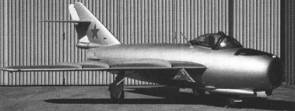
The MiG-19 was on the drawing board as the I-350 before even the MiG-15 had been encountered in Korea, the five prototypes being ordered on 30 July 1951. Maj Grigori Sedov flew the first I 350 design, also known as the Type SM, on 18 September 1953 on the power of two non-afterburning AM-5 engines giving only 4,410 lb thrust each.

Mikoyan-Gurevich MiG-19 Article

Despite the high wing loading and bold sweep angle of 55 (at 25% chord), the MiG-19 handled well, large fences and Fowler flaps giving satisfactory low-speed control With afterburning engines the MiG-19 became the first Russian supersonic fighter and it was put into production on a very large scale in the second half of the following year.

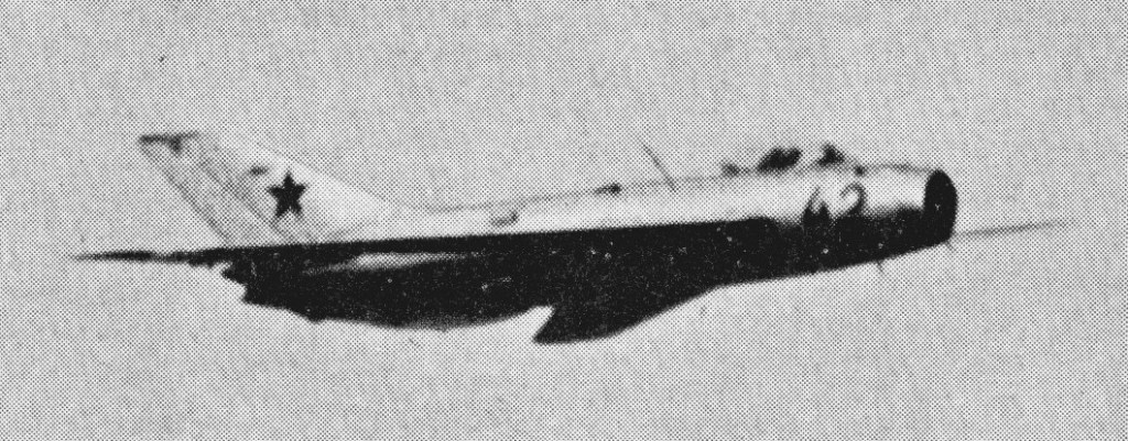
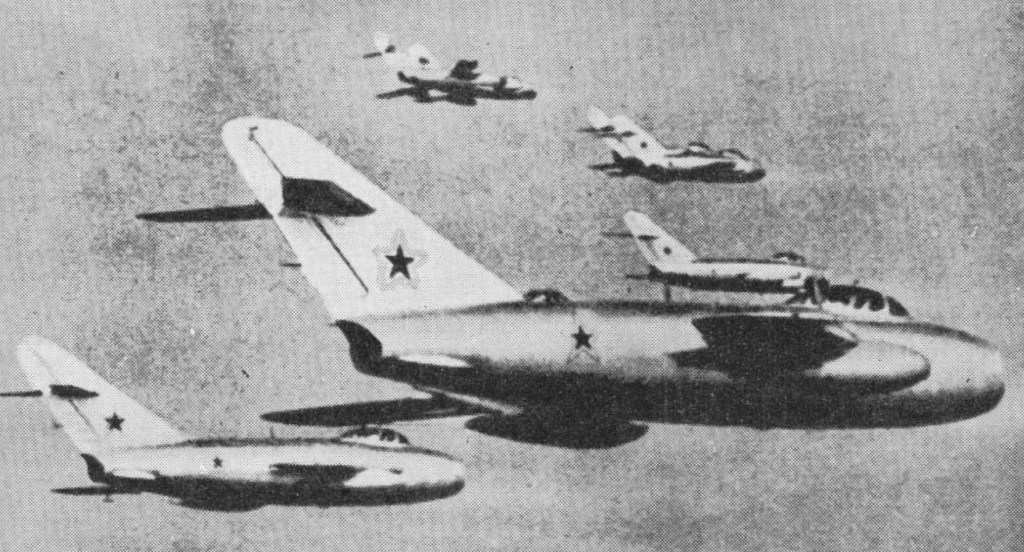
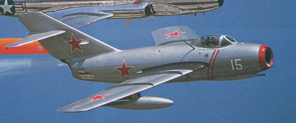
Deliveries to the Soviet air force began early in 1955, and 48 flew in formation at that year’s Soviet Aviation Day, held at Tushino. Early MiG-19s were pow¬ered by a pair of Mikulin AM 5 axial flow turbojets each producing 2250 kg (5000 lb) of thrust dry and 3040 kg (6700 lb) with after¬burning. The engines are mounted side by-¬side in the rear fuselage and fed from a divided annular intake in the nose. The three-¬spar wings are tapered and swept back by 55 deg at 25% chord, with a full chord fence on each side. Anhedral is about 4.5 deg. The large area Fowler flaps can be used at up to 800 km/h (495 mph) in combat, and lateral control in later aircraft is effected by ailerons assisted by spoilers, this arrangement having been used first on the MiG-15SD.

The area ruled fuselage has a cylindrical nose and carries a cluster of air scoops at the rear to cool the afterburners, with others on either side of the spine feeding the elec¬tronics bays. Air brakes were fitted to the fuselage sides in early models, later aircraft having an additional one mounted ventrally. The fin and fuselage mounted tailplanes are swept back.

After about 500 had been delivered the MiG-19S (stabilizator) supplanted the early model with the fixed tailplane and manual elevators replaced by a fully powered slab. At the same time the old armament of a 37 mm (1.46 in) N 37 cannon with 40 rounds in the right hand side of the forward fuselage and a 23 mm (0.90 in) NR 23 with 80 rounds in each wing was replaced by three of the new 30 mm NR-30 guns, one in each wing root and one under the right side of the nose and was fitted with two air to¬-surface weapon stations under the wings. A large ventral airbrake was also added.

Fuel is carried in four fuselage cells with a total capacity of 2170 litres (477 Imperial gal) and can be supplemented by a pair of underwing drop tanks containing 800 litres (176 Imperial gal) each. A dorsal spine housing control, running between the cockpit and the tail, was introduced into the MiG¬-19S. A fully duplicated hydraulic system was employed and the tailplane was geared electro mechanically to operate at a nearly con¬stant rate of stick force per g. An electrical system was provided to operate the tailplane in the event of hydraulic failure. The MiG-19S entered full service in the second half of 1956.

In 1956 the AM-5 engine was replaced by the newer and more powerful Tumansky RD 9Bs each rated at 2600 kg (5730 lb) dry and 3250 kg (7165 lb) with reheat, increasing peak Mach number from 1.1 to 1.3. The new fighter was designated MiG-19SF (forsiro¬vanni, increased power) which was code named Farmer C and has been built in very large numbers.

The corresponding MiG-19PF (perekhvatchik, inter¬ceptor) has an Izumrud Al radar (called “Scan Odd” by NATO) in a bullet carried on the inlet duct splitter, with the ranging unit in the upper inlet lip. The final production version was the MiG-19PM (modifikatsirovanni), with guns removed and pylons for four early beam-rider air-to-air missiles (called “Alkali’ by NATO), an all weather version fitted with the X band Scan Odd fire ¬control radar using dual pulse repetition fre¬quencies. The main antenna was housed in a bullet fairing mounted on the central intake splitter, with the complementary ranging radar installed in the upper lip.

A two seat version, the MiG¬19UTI, was also delivered.

All MiG-19s can carry the simple K-13A missile (the copy of Sidewinder, called “Atoll” by NATO) and underwing pylons can carry two 176 gal drop tanks plus two 551 lb weapons or dispensers. The Mig-19 was out of production in 1957.

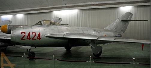
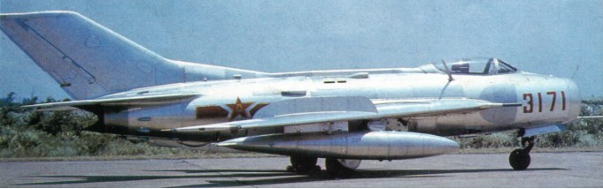
The type was supplied to China knocked-down MiGs for Chinese construction before relations soured in 1960, and the Shenyang National Aircraft Factory has copied the MiG 19S as the F 6 (first flight in December 1961). Production of the F-6 was stepped up from about 1966 and it is thought that several thousand have been built, including counterparts of the MiG-19PF and SF. F-6 became the standard equipment of the Chinese Air Force of the People’s Liberation Army from mid-1962. China has developed a number of variants of its own design. One is a tactical reconnaissance aircraft, while the TF-6 is a trainer version and the A-5 (formerly referred to as the F-9 and F-6 bis) a strike fighter with different appearance because of its pointed nose radome between the semi-circular side air intakes. The span of the A-5 has also been increased to about 10.2m. Maximum level speed of this version is estimated to be close to Mach 2.

Chinese built F 6s have been supplied to ‘friendly’ coun¬tries, including Pakistan, and are thought to incorporate indigenously developed improve¬ments. The Pakistani aircraft have performed well in periodic clashes against Western ¬supplied types and MiG 21s operated by the Indian air force.

Phased out of production in the Soviet Union during the late 1950s, the Mikoyan-Gurevich MiG-19 continued to be built in China under a licence agreement of January 1958. The J-6 (Jianjiji 6, or Fighter Aircraft Type 6) is normally credited to the Shenyang production facility, although a second assembly line is located at Tianjin. First of the Chinese production models was the J-6 equivalent of the MiG-19S/SF day fighter, this giving way to the J-6A/MiG19PF limited all-weather interceptor and the later J-6B/MiG-19PM, the latter augmenting gun and rocket armament by AA-1 ‘Alkali’ AAMs. An improved MiG-19SF, known as the J-6C and identified by a brake parachute housing at the base of the fin was in production in 1984, as was J-6Xin (‘New J-6’) which featured a sharply-pointed radome in the engine air intake for a Chinese-developed airborne gun-ranging radar. The JZ-6 (Jianjiji Zlienchaji 6) is a MiG-19R reconnaissance version equivalent with the forward fuselage cannon replaced a camera array. Despite limited Soviet production of a MiG-19UTI, Chinese requirements for a dual control trainer were met by a local design to produce the JJ-6 (Jianjiji Jiaolianji 6), with its 0.84 m (2 ft 9 in) fuselage extension. Several thousand J-6s have been built for the Chinese army and navy air forces since 1961, whilst export variants (known as the F-6 and trainer FT-6) serve in Albania, Bangladesh, Egypt, Iraq, Pakistan, Tanzania and Vietnam as interceptors and close-support aircraft. The J-6 is well liked by its pilots as a manoeuvrable fighter and stable weapons platform, Pakistan’s aircraft having been improved by the addition of a third (under-fuselage) fuel tank, US-designed AIM-9B/J Sidewinder AAMs and Martin-Baker PKD Mk 10 automatic zero-zero ejection seats.

Total production possibly exceeds 10,000, including licence-manufacture as the Lim-7 in Poland, S-105 in Czechoslovakia and F-6 in China.

The MiG 19 has also been used as a testbed in a number of experimental programmes. Under the designation SM 10 it was used for in flight refuelling trials from 1955, and in 1957 the SM 12.

SM 30 was the bureau designation of a pre-¬series MiG 19 which was used for catapult takeoff trials in 1956, and three years later the SM 50 underwent tests while fitted with RD¬9BM turbojets of 3300 kg (7275 lb) thrust each with reheat, augmented by a U 19 rocket motor producing 3200 kg (7055 lb). A maximum speed of 1800 km/h (1118 mph) was attained, and a height of 20 000 m (65 600 ft) was reached in eight minutes.

Gallery

MiG-19
Single-seat fighter
Engines: 2 x Mikulin AM-5 turbojets, 6.700 lb (3,040 kg) thrust (afterburner rating)
Wing span 29 ft 6.5 in (9 m)
Height 13 ft 2.25 in (4.02 m)
Max speed (typical) 920 mph @ at 20,000 ft (M 1.3)

MiG-19
Single-seat fighter
Engines: 2 x Mikulin VK-5 turbojets, 8818 lb
Wing span: 36 ft 6 in
Length: 44 ft 3 in
Height 13 ft 6 in
MTOW: 19,840 lb
Max speed: 860 mph at 36,000 ft (M1.3)
Max OC: 15,000 fpm
Service ceiling: 58,000 ft
Max range: 850 mi

MiG-19S
Single-seat fighter
Engines: 2 x Mikulin AM-5 turbojets, 6.700 lb (3,040 kg) thrust (afterburner rating)
Wing span 29 ft 6.5 in (9 m)
Length: 42 ft 11.25 in (13.08 m)
Height 13 ft 2.25 in (4.02 m)
Max speed (typical) 920 mph @ at 20,000 ft (M 1.3)
Gross weight: 8700 kg (19180 lb)

MiG-19SF
Single-seat fighter
Engines: 2 x Klimov RD-9B turbojets, 7,165 lb (3250 kg) thrust (afterburner)
Wing span 29 ft 6.5 in (9 m)
Length: 42 ft 11.25 in (13.08 m)
Height 13 ft 2.25 in (4.02 m)
Initial ROC: 22,640 ft (6900 m)/min
Service ceiling: 58,725 ft (17,900 m)
Max speed (typical) 920 mph @ at 20,000 ft (M 1.3)
Empty wt: 12,698 lb (5760 kg)
Loaded wt (clean): 16,755 lb (7600 kg)
MTOW: 19,180 lb (8700 kg)
Max range (high. with two drop tanks): 1,367 miles (2200 km)

MiG-19
Engines: 2 x turbo-jet RD-9B(N), 31.9kN
Max take-off weight: 8600 kg / 18960 lb
Wingspan: 9.0 m / 29 ft 6 in
Length: 12.5 m / 41 ft 0 in
Height: 4.1 m / 13 ft 5 in
Wing area: 23.0 sq.m / 247.57 sq ft
Max. speed: 783 kts / 1450 km/h / 901 mph
Service ceiling: 18600 m / 61000 ft
Range w/max.fuel: 2200 km / 1367 miles
Range w/max.payload: 1400 km / 870 miles
Armament: 3 x 30mm machine-guns, missiles
Crew: 1

MiG-19PF
All-weather interceptor
Engines: 2 x Klimov RD-9B turbojets, 7,165 lb (3250 kg) thrust (afterburner)
Wing span 29 ft 6.5 in (9 m)
Length: 44 ft 7 in
Height 13 ft 2.25 in (4.02 m)
Max speed (typical) 920 mph @ at 20,000 ft (M 1.3)
Max range (high. with two drop tanks): 1,367 miles (2200 km)

MiG-19PM
All-weather interceptor
Engines: 2 x Klimov RD-9B turbojets, 7,165 lb (3250 kg) thrust (afterburner)
Wing span 29 ft 6.5 in (9 m)
Length: 44 ft 7 in
Height 13 ft 2.25 in (4.02 m)
Max speed (typical) 920 mph @ at 20,000 ft (M 1.3)
MTOW: 20,944 lb (9500 kg)
Max range (high. with two drop tanks): 1,367 miles (2200 km)

Lim-7

S-105

F-6 / Shenyang/Tianjinj-6C
Powerplant: two 3250-kg (7,165-lb) Shenyang Wopen-6 (Tumansky R-9BF-811) afterburning turbojets
Maximum speed, clean 1540 km/h (957 mph) or Mach 1.45 at 11000 m (36,090 ft)
Maximum speed 1340 km/h (833 mph) or Mach 1.09 at low level
Service ceiling 17900 m (58,725 ft)
Empty weight 5760 kg (12,698 lb)
Normal take-off weight, clean 7545 kg (16,634 lb)
Maximum take-off with external stores about 10000 kg (22,046 lb)
Wing span 9.20 m (30 ft 2.25 in)
Length, excluding probe 12.60 m (41 ft 4 in)
Height 3.88 m (12 ft 8.75 in)
Wing area 25.00 sq.m (269 sq ft).
Armament: three internal 30-mm NR30 cannon (one on starboard side of nose, two in wing roots); wing pylons for two 250-kg (551 -1b) bombs or four rocket packs, plus fuel tanks.

Mikoyan-Gurevich MiG-19

Mikoyan-Gurevich MiG-17 / I-330 / Aero Vodochody S.104 / WSK-PZL-Mielec LIM-5 / LIM-6 / Shenyang J-5

Mig-17PM

Early in 1949, in parallel with work on the SD (MiG-l5bis), the MiG OKB launched a more thoroughgoing redesign of the basic MiG-15 as the SI, alias 1-330. The SI was intended to afford improved transonic behaviour, achieved by mating the existing fuselage (forward of the rear frame of the engine plenum chamber) with a lengthened rear fuselage and an entirely new wing possessing better compressibility charac¬teristics, having leading-edge sweep of 45 deg inboard and 42 deg outboard. A mark of identification was the MiG-17’s three boundary layer fences on each wing.

The Klimov VK-l engine of the SD was retained, together with the armament of one 37-mm and two 23-mm cannon. The first prototype, officially flown on 13 January 1950, allegedly attained M 1.03, but crashed in March 1950. Following the loss of the first prototype, a second and further improved prototype took over, the test programme being completed on 20 June 1951 and series production being ordered as the MiG-17. Production began with a day fighter model (NATO `Fresco-A’), which retained the VK-1 engine.

Mikoyan-Gurevich MiG-17 Article

The MiG 17 was preferred to the Yak 50 and entered service with the Soviet air force in its Fresco A form during 1952. Its power¬plant was a Klimov VK 1 turbojet producing 2700 kg (5950 lb) of thrust, the same as in the MiG 15 bis, and the armament was similar: one 37 mm (1.46 in) N 37 cannon and a pair of 23 mm (0.90 in) NR 23s, aimed with the aid of a simple gyro gunsight. Air to surface armament could also be carried in the form of four UV 8 57 pods each containing eight 5.5 cm (2.16 in) S 5 rockets, two 21 cm (8.26 in) rockets, two 250 kg (551 1b) bombs or 240 litre (53 Imp gal) drop tanks. The use of steel underwing beams allowed two rocket pods or bombs to be carried inboard, with drop tanks on the outboard pylons.

Fresco B was the MiG-17P, flown as a prototype in 1951, fitted with an S band ‘Izumrud’ (Emerald) radar, known as Scan Fix in the West, with the main dish mounted on the intake splitter and the rang¬ing element housed above in the lip discardingd the 37-mm cannon in favour of a third 23-mm weapon. The fuselage was lengthened by 127 mm (5 in) and the cockpit glazing was modified to cater for additional displays. In the event, production of the MiG-17P was to be limited pending availability of the afterburning VK-1F engine.

Experimental versions included the SN, a ground attack model of the VK-1-engined fighter, which, flown in November 1953, featured lateral air intakes and twin 23-mm nose-mounted cannon which could be hydraulically elevated or depressed (± 40 deg). Another, the SP-2 flown in 1951, was a limited all-weather version with a higher-powered Korshun (Kite) search radar and a twin 23-mm cannon armament. During the course of 1953, production of the MiG-17 gave place to the improved MiG-17F.

Availability of an afterburning version of the Klimov engine, the VK-1F offering 7,452 lb st (3 380 kgp) for three minutes, resulted in the SF, which, flown in 1951, was cleared for series production as the MiG-17F Fresco C (Forsirovannyi, or, literally, “boosted”) in April 1953. Apart from a cut-back rear fuselage exposing the variable nozzle, the MiG-17F featured shorter and deeper air brakes; those on the new variants were larger than their predecessors, mounted in a different position on the fuselage and operated by external jacks.

Large-scale production of the MiG-17F was paralleled by production of the similarly-powered MiG-17PF limited all-¬weather fighter with a trio of 23-mm cannon and (from the 26th aircraft) the improved RP-5 Izumrud radar in a bullet' radome at the centre of the nose air intake and in an extension on the upper lip of the intake. Subsequently, this S-band radar was superseded by an E/F-band version ofScan Fix’, which still gave neither a large antenna nor a wide angle of scan.

In 1953, gun armament was deleted from a MiG-I7PF and provision made for a quartet of K-S (ARS-212) beam-riding missiles mounted on underwing pylons, this version entering production in 1955 as the MiG-I7PFU (Usovershenstvovanny, or, literally, “improved”).

The MiG 17PF Fresco D entered service in 1955 and was fitted with progressively improved versions of Izurnrud/Scan Fix, operating in X band as well as the original S band, and in the MiG-17PFU Fresco E variant the gun armament was replaced by four beam riding AA 1 Alkali air to air mis¬siles carried on underwing pylons projecting forward of the leading edge. Some MiG-17s were fitted out for reconnaissance, with cameras in the forward fuselage and only two guns, and the type has increasingly been used for ground attack as it was replaced in the interception role.

The MiG-17PM (Nato Farmer D) being an all weather fighter carrying only air-to-air missles as armament.

Production of the MiG-17F and MiG-17PFU continued in the Soviet Union until 1958, and licence manufac¬ture of the MiG-17F was initiated in 1957 in Poland as the LIM-5P (licencyjny mysliwiec, or “licensed fighter”), remaining in production until 1960. The MiG-17F was in service with that country’s Soviet-dominated air force in the late 1950s. The lead company, WSK-PZL-Mielec, also carried out design work on various modified versions, some greatly altered. Production continued until 1961. Dedicated reconnaissance and ground attack variants evolved designated LIM-5R and LIM-6.

Polish production of the MiG-17PF (LIM-5M) being initiated in 1959 and continuing until 1961. Dedicated reconnaissance and ground attack variants evolved in Poland were designated LIM-5R and LIM-6. Licence production was also undertaken of the MiG-17F (as the Jian5) and MiG-17PF (Jian-5A) by Shenyang in China commencing late 1956, and a uniquely Chinese tandem two-seat advanced training version was developed as the JT-5.

MiG-17 was license built China and known as Type-56, Dong Feng 101 and later is was dubbed J5 in Peoples Republic of China Air Force service. The first J5 prototype carried ‘Zhong-0101’.

J5 prototype
J5

Some Polish LIM 5P’s were modified to LIM 5M standard by fitting additional fuel tanks and a twin wheel main undercarriage with low pressure tyres which retracted into a larger wing centre section built of rein-forced plastics. A relatively small number were converted, but many others were upgraded to LIM 6 standard by introducing a braking parachute, rocket assisted takeoff units and additional stores pylons. The LIM-6, together with the LIM 6bis having modified ordnance racks and the reconnaissance LIM 6R, remained in Polish service until replaced by the Su 20 Fitter C.

LIM-5

The earlier model had been constructed as the Czech S.104.

1721 Mikoyan-Gurevich Lim-5 R 1C-17-21

Licence production was undertaken of the MiG-17F (as the Jian-5) and MiG-17PF (Jian-5A) in China commencing late 1956, and a uniquely Chinese tandem two-seat advanced training version was developed as the JT-5.

A total of 11,015 was built (including licence production). The last one was built in 1958 but the type was exported more widely than any other Soviet military aircraft. The Fresco was withdrawn from Soviet air force service in the late 1960s but soldiers on in many parts of the world, typical ground-¬attack weapons comprising 250 kg (551 1b) bombs, UV 16 57 rocket pods and S 24 rockets.

Gallery

Mikoyan-Gurevich MiG-17
Engine: 1 x Klimov VK-1 turbojet, 5,952 lbs thrust
Wing Span: 31 ft 7 in
Length: 36 ft 5 in
Height: 12 ft 6 in
Light weight: 8,646 lb
Loaded weight: 11,803 lb
Ceiling: 52,366 ft
Speed: 696 mph
Range: 1,290 miles (ferry)
Crew: 1
Armament: 2 x 23mm cannon, 1 x 37 mm cannon, 4 x 57mm rocket pods

MiG-17
Engine: 1 x VK-1F(N) turbo-jet
Wingspan: 9.6 m / 31 ft 6 in
Length: 11.4 m / 37 ft 5 in
Height: 3.8 m / 12 ft 6 in
Wing area: 22.6 sq.m / 243.26 sq ft
Max take-off weight: 5200 kg / 11464 lb
Max. speed: 1114 km/h / 692 mph
Ceiling: 15000 m / 49200 ft
Range: 2000 km / 1243 miles
Crew: 1
Armament: 1 x 37mm machine-guns, 2 x 23mm machine-guns, bombs or missiles

MiG-17
Engine: 1 x Klimov VK-1 turbojet, 5952 lb (later models) VK-1F, 4732 lb / afterburner-7452 lb)
Max speed, 692 mph (1114 km/h) at 6,560 ft (2 000 m)
Initial climb, 9,252 ft/min (47 m/sec)
Range (with max external fuel), 1,336 mls (2150 km)
Empty weight, 8,373 lb (3798 kg)
Loaded weight (clean), 11,468 lb (5202 kg)
Span, 31 ft 7 1/8 in (9,63m)
Length, 36ft l1 1/3 in (1l,26m)
Height, l2 ft5 5/8 in (3,80 m)
Wing area, 243.26 sq ft (22,60 sq.m)

MIG-17F ‘Fresco-C’
Type: single-seat fighter
Powerplant: one 3400-kg (7,495-lb) afterburning thrust Klimov VK-JF turbojet
Maximum speed 1145 km/h (711 mph) at 3000m (9,845 ft)
Initial climb rate 3900 m (12,795 ft) per minute
Service ceiling 16600 m (54,460 ft)
Range (with max external fuel): 1470 km (913 sm)
Empty weight: 4100 kg (9,040 lb)
Maximum take-off weight: 6700 kg (14,770 lb)
Wingspan 9.63 m (31 ft 7 in)
Length 11.09 m (36 ft 4½ in)
Height 3.35 m (11 ft)
Wing area 22.60 sq.m (243.3 sq ft)
Armament: three 23-mm NR-23 cannon, plus four AA-1 ‘Alkali’ missiles or up to 500 kg (1, 102 lb) of external stores.

MiG-17P
Engine: 1 x Klimov VK-1 turbojet, 5952 lb (later models) VK-1F, 4732 lb / afterburner-7452 lb)
Wing span: 31 ft (9.45 m)
Length: 36 ft 3 in (11.05 m)
Height 11 ft (3.35 m)
Empty wt: 9040 lb
MAUW: 14,770 lb

MiG-17PF
Wing span: 31 ft (9.45 m)
Length: 36 ft 3 in (11.05 m)
Height 11 ft (3.35 m)
Empty wt: 9040 lb
MAUW: 14,770 lb

MiG-17PM
Wing span: 31 ft (9.45 m)
Length: 36 ft 3 in (11.05 m)
Height 11 ft (3.35 m)
Empty wt: 9040 lb
MAUW: 14,770 lb
Armament: 4 x AA-1 missiles.

LIM-5P
Engine: Kumov VK1A turbojet
Seats: 1

Mikoyan/Gurevich MiG-17

Mikoyan-Gurevich MiG-15 / I-310 / Shenyang F-2 / FT-2 / Aero Vodochody S-103 / CS-102 / PZL-Mielec Lim-2 / SBLim-1

The I-310(S) was designed to meet a March 1946 requirement for a high-altitude day interceptor. The Mikoyan/Gurevich, Lavochkin and Yakovlev design bureau competed for the production contract, striving to meet the specification of a Mach 0.9 top speed, high rate of climb to 10000 m (32800 ft), good manoeuvrability at this height and above, a minimum of one hour’s duration and cannon armament, combined with simplicity of design and operation.

The need for a near sonic speed demanded the adoption of wing sweep, and the design team was able to draw on the expertise of Gurevich himself, in addition to other work carried out by Russian and German engineers. A swept forward wing layout was examined but discarded in favour of the swept back solution. The aircraft was designed around the RD-10A turbojet of 1000 kg (2205 lb) thrust, based on the German Jumo 004. A Russian designed powerplant with twice the thrust was in the pipeline and was expected to become available within a year, but the Anglo Soviet trade agreement of 1946 offered a more attractive possibility.
The trade pact included the supply of 25 Rolls Royce Nene turbojets, most of which were allocated to the Klimov engine design bureau or to research establishments. One was supplied to the Mikoyan/Gurevich team and the MiG 15 was redesigned to accommodate the fatter Nene, which had a centrifugal compressor compared with the axial unit or the Russian engine under development, and which also produced greater thrust. The Rolls-Royce Nene immediately went into production at No 45 production factory in Moscow, designated RD-45 after the factory.

Mikoyan-Gurevich MiG-15 Article

The layout involved air fed from a bifurcated nose intake via four ducts which passed either side of the cockpit and then over and under the unbroken wing centre section. The wing, of almost parallel chord, was swept back by 35 degrees at the leading edge and was built up from two main spars skinned with light alloy. The upper surfaces carried two full chord fences on each side and large Fowler flaps, set at 20 degrees for takeoff and 55 degrees for landing, were attached to the wing, just forward of the trailing edge. The ailerons were the only power operated aerodynamic controls.

The circular section fuselage was constructed in two halves which could be separated by means of quick release bolts at the attachment point for the rear wing spar, exposing the complete engine for maintenance. Air brakes were fitted on either side of the rear fuselage. The tailplane was swept back by 40 degrees and its incidence could be adjusted manually before takeoff. Two fuel tanks in the rear fuselage carried 90 litres (19.8 Imp gal) each, but the majority was contained in a 1225 litre (269 Imp gal) tank fitted between the wing spars. The undercarriage had a wide track 4 m (13 ft 1.5 in) to allow operation from rough fields; the levered suspension mainwheels retracted inwards to lie within the fork of the front main spar.

Navigation, communication and fire-control equipment was extremely simple but this solution proved to be the correct solution when the type was blooded in combat. A gyro gunsight (copied from the British GGS Mk 2) with a maximum range of 800 m (875 yards) was used to aim the two 23 mm (0.90¬in) NS 23 cannon mounted in a pack under the nose. This arrangement was later replaced by a single 37 mm (1.46 in) N 37 cannon with 40 rounds on the right hand side and a pair of NS 23s with 80 rounds each on the left. The wing hardpoints were stressed to carry up to 500 kg (1102 lb) of bombs, although two weapons of 100 kg (220 lb) each were more usual, and rockets were also fitted. Alternatively, auxiliary fuel tanks could be carried to increase endurance.

It seems likely that the first prototype of the MiG-15, designated I 310, made its maiden flight in July 1947, but crashed during low speed trials. Several design changes were introduced as a result, including the adoption of 2 degrees of wing anhedral in place of the dihedral layout, installation of wing fences and several changes to the back end. The rear fuselage was shortened and the jet pipe cut back to reduce the amount of engine power being lost, the tailplane was removed from the top of the fin and repositioned two thirds of the way up, and the fin itself was swept back by 56 degrees. The first of two replacement prototypes, the S-01, was flown on 30 December 1947. As the I 350 prototype, it flew for the first time in September 1953.

The revised design was far from perfect – it tended to enter a spin from a tight turn, necessitating the fitting of recovery rockets but it was apparent that the layout was basically sound. The Mikoyan/Gurevich team had six months’ headway over their competitors, and this proved decisive, although both the La 168 and Yak 30 proceeded to the flight-test stage and the former entered limited production.

Reverse engineering of the Nene by Vladimir Klimov’s bureau had paralleled design development of the I-310, and as the RD-45 of 4,850 lb st (2 200 kgp), this engine powered the initial series fighter, which, as the MiG-15, was cleared for production in March 1948 (NATO Fagot), the first pre-series aircraft being delivered to the NII for evaluation seven weeks later, on 10 May.

Early production MiG-15s powered by the RD 45, copied from the Nene, reached the squadrons before the end of 1948. The RD 45F (Forsirovanny, meaning boosted), uprated from 2200 kg (4850 lb) to 2270 kg (5000 lb) thrust for take¬off, soon replaced the earlier powerplant at an early production stage. Armament comprising one 37-mm N-37 and two 23-mm NS-23KM cannon.

Production under licence was begun in Poland as the LlM-1 and in Czechoslovakia as the S-102.

Variants of the RD-45F-powered fighter included the MiG-15PB escort fighter with two 132 Imp gal (600 lt) underwing slipper tanks, the MiG-15P with a pre-series Izumrud (Emerald) radar and the MiG-15SV with faster-firing NR-23 cannon, none of these being built in quantity.

A structural reappraisal of the basic MiG-15 resulting in a 198 lb (90 kg) weight reduction, minor aerodynamic changes, upgraded equipment and a Klimov-developed VK-1 turbojet (origi¬nally designated RD 45FA) rated at 5,952 lb st (2 700 kgp) for takeoff, or 3000 kg (6615 lb) with water injection produced the MiG-15SD flown in September 1949. With some further changes (which in¬cluded modifications to the ailerons and air brakes) this was placed in production in the following year as the MiG-15bis. The engine’s external dimensions remained the same, but the mass flow was increased and the larger diameter hot end resulted in dry weight rising from 870 kg (1918 lb) in the RD 45 to 875 kg (1930 lb) in the VK 1. Fuel capacity was increased by 160 litres (35 Imp gal) and improved equipment was fitted. Perforated flaps were therefore adopted to save airframe weight, offsetting increases in other areas. Late production models of the MiG-15bis, which was the variant built in the largest numbers, carried 23 mm (0.90 in) NR 23 revolver cannon in place of the slow firing NS 23s. Polish and Czech versions were designated LIM-2 and S-103.

Lim-2

The MiG 15bis was followed by the two seat MiG-15UTI, code¬named Midget, with the instructor sitting behind and slightly above his pupil. Some fuel capacity was sacrificed, and the top speed dropped slightly. The principal production version of the basic design, with several thousand being built until late 1951, plus others licence-built in Czechoslovakia and Poland (as the LIM-3).

LIM-3

The MiG-15bis standardised on an armament of two 23-mm NR-23 cannon and one 37-mm N-37 cannon.

Limited all-weather versions with Izumrud radar included the MiG-15SP-1 and SP-2. The two seater was also used for ejection seat experiments and formed the basis of the SP 5, the first all-weather fighter variant. An Izumrud (Emerald) fire control radar (NATO code name Scan Fix) was fitted, the antenna being mounted in a bullet fairing in the centre of the intake splitter. A complementary ranging radar was installed in the top lip of the intake. The definitive all weather fighter variant, the MiG-15P, was, however, a single seater derived from the MiG-15bis.

Other experimental models were the MiG-15SU for ground attack and featuring a pack containing cannon angled to fire downward, the MiG-15bisSB (ISh) intended for the shturmovik role and the MiG-15bisS escort fighter with 132 Imp gal (600 1t) slipper tanks, reduced armament and other changes.

A reconnaissance version, the MiG-15bisR with full armament and fitted with a single nose mounted vertical camera below the gun magazines was developed for high altitude sorties over Korea and was additionally employed in Europe.

A further variant was the MiG-15SB, which had twin beams extending from the wing leading edges to carry two 100 kg (220 1b) bombs, eight 55 mm (2.16 in) rockets or auxiliary fuel tanks. Rockets were fitted to reduce the takeoff run and a braking parachute similarly shortened the landing roll.

Production in the Soviet Union ended in 1953.

On 10 March 1953, five days after a Polish pilot had defected with his MiG-15 to the Danish island of Bornholm, two Czechoslovakian MiGs attacked two American F-84G Thunderjets over Regensburg in Bavaria. One of the Thunderjets was shot down by the 23mm and 37mm cannon of one of the MiGs. The pilot ejected safely over Czechoslovakian territory.

The last RB-29 was shot down by two MiG-15s above the east coast of Hokkaido, Japan, on 4 September 1954. The aircraft allegedly flew over Soviet territory on the Pacific coast, according to the Sovies. Ten or elevel of the crew survived.

One of the most widely used jet fighters of all time, the MiG-15bis was also manufactured in China (as the Shenyang F-2, and the MiG-15UTI as the Shenyang FT-2), Czechoslovakia (Mig-15bis as the Aero Vodochody S-103 and the Mig-15UTI as the CS-102) and Poland Czechoslovakia (Mig-15bis as the PZL-Mielec Lim-2 and the Mig-15UTI as the SBLim-1) in considerable numbers and it is known to have served with close to 30 air arms throughout the world as a front-line fighter and as an advanced trainer.

Large numbers (over 1,000) of early versions were supplied to China and North Korea, entering combat in 1951. No Allied fighter could stay with it and even the technically superior F-86 had inferior climb, ceiling and high-altitude turn radius. Many thousands (14,000+) of all versions were built, and the MiG-15 remained an invaluable aircraft for air forces with little jet experience, being supplied to at least 18.

The MiG 15 took part in the first ever all jet air combat when one was destroyed by a Lockheed F 80 Shooting Star of the US Air Force over Korea on November 7, 1950, some six days after the Russian type was deployed to that theatre. The Soviet aircraft was more manoeuvrable and had a higher ceiling than its US adversaries, and the slow ¬firing but hard hitting cannon carried a heavier punch than the machine guns of the opposing fighters. The USAF’s response was to introduce the North American F 86A Sabre, which scored its first MiG kill on December 17, 1950. The North Korean and Chinese pilots could not hope to match the experience of their adversaries, and on May 20, 1951, Capt James Jabara bagged his fifth and sixth MiG 15s to become the first jet ace. The USAF alone claimed 792 MiG 15s destroyed over Korea, while the US Navy also notched up a creditable score, bringing the claimed kill to loss ratio to about 12:1.

Gallery

MiG-15
Engine: 1 x Klimov RD-45F, 5,005 lb st (2270 kgp)
Max speed, 648 mph (1043 km/h) at 9,845 ft (3000 m)
Max initial climb, 8,268 ft/min (42 m/sec)
Range (clean), 882 mls (1 420 km) at 236 mph (380 km/h) at 39,370 ft (12 000 m)
Empty weight, 7,456 lb (3 382 kg)
Loaded weight (clean), 10,595 lb (4 806 kg)
Span, 33 ft 1 in (10,08 m)
Length, 32 ft 1¼ in (10,04 m)
Height, 12 ft 1 2/3 in (3,70 m)
Wing area, 221.75 sq ft (20,60 sq.m).

Engine: 1 x VK-1 turbo-jet, 26.5kN / 5950 lb
Wingspan: 10.1 m / 33 ft 2 in
Wing area: 20.6 sq.m / 221.74 sq ft
Length: 10.1 m / 33 ft 2 in
Height: 3.7 m / 11 ft 2 in
Empty weight: 13,249 lb
Max take-off weight: 4960 kg / 10935 lb
Max. speed: 1076 km/h / 669 mph
Max ROC: 19,400 fpm
Ceiling: 16000 m / 52500 ft
Range w/max.fuel: 2000 km / 1243 miles
Range w/max.payload: 1400 km / 870 miles
Armament: 1 x 37mm cannon, 2 x 23mm machine-guns, 400kg of bombs or missiles
Crew: 1

MiG-15P
Equipment: Izumrud (Emerald) radar.

MiG¬-15PB
Type: escort fighter
Fuel cap: two 132 Imp gal (600 1t) underwing slipper tanks

MiG-15SV
Armament: faster-firing NR-23 cannon

MiG-l5bis
Powerplant: one 2700-kg (5,952-lb) thrust Klimov VK-1 turbojet / later models one 6990-lb thrust Klimov VK-1A turbojet.
Maximum speed 1100 km/h (684 mph) at 12000 m (39,370 ft)
Initial climb rate 3500 m (11,800 ft) per minute
Service ceiling 15550 m(51,015 ft)
Ferry range 2000 km (1,242 miles)
Empty weight 3400 kg (7,495 lb)
Maximum take-off 5785 kg(12,756 lb)
Wingspan 10.08 m (33 ft 0¾ in)
Length 11.05 m (36 ft 3¼ in)
Height 3.40 m(11 ft 1¾ in)
Wing area 20.60 sq.m (221.7 sq.ft)
Armament: one 37-mm NR-37 cannon and two 23-mm NR-23 cannon, plus up to 1000 kg (2,205 lb) of external stores.

MiG-15Bis (SD)
Max speed, 692 mph (1114 km/h) at 7,220 ft (2 200 m)
Time to 16,405 ft (5 000 m), 2.1 min.
Range (clean), 826 mls (1330 km)
Empty weight, 8,115 lb (3 681 kg)
Loaded weight (clean), 11,175 lb (5069 kg)
Span, 33 ft 1 in (10,08 m)
Length, 35 ft 7½ in (10,86 m)
Height, 12 ft 1 2/3 in (3,70 m)
Wing area, 221.75 sq ft (20,60 sq.m)
Armament: two 23-mm NR-23 cannon and one 37-mm N-37 cannon.

Engine one 7,452-lb Klimov VK- 1F turbojet
Gross wt. 12,000 lb
Empty wt. 8,115 lb
Max speed 668 mph
Range 450 nm
Ceiling 50,855 ft
Seats 1-2.

MiG-15UTI
Engine: LIS-2, 5500 lb thrust.
Fuel cap: Internal: 1000 lt, external 2 x 400 lt.
ROC: 6000+ fpm.
Service ceiling: 48,000 ft.
Loading: Clean, +8g, With drop tanks full, +4g.
Max speed: 570 kts (M 0.92), with drop tanks, 430 kts.
Stall: 110-103 kts.

MiG-15UTI
Type: Two seat fighter/trainer
Engine: One Klimov RD-45 turbojet, 5,005 lbs thrust
Empty weight: 7,900 lb
Loaded weight: 10,935 lb
Wing Span: 33 ft 1 in
Length: 33 ft 2 in
Height: 12 ft 2 in
Ceiling: 50,580 ft
Speed: 668 mph
Range: 1,225 miles (ferry)
Armament: 2 x 23mm cannon, 1 x 37 mm cannon, 2 x 100 kg bombs or rockets

Mikoyan-Gurevich MiG-3

Lacking the time for a redesign of the MiG-1 to eradicate the fighter’s less acceptable characteristics, a series of ‘fixes’ were applied to the basic design to result in the MiG-3.
Power plant and (initially) armament remained unchanged, but some structural simplification and strengthening was introduced. The engine was moved forward 10cm and dihedral of the outer wing panels was increased by one degree. A 250 lt supplementary fuel tank was introduced beneath the pilot’s seat, the aft fuselage decking was cut down, and the radiator bath fairing was enlarged and extended forward. The supercharger intakes were revised; 9mm seat armour was provided, together with radio, and four wing hardpoints were introduced for a maximum external load of 220kg.

Mikoyan-Gurevich MiG-3 Article

The first MiG-3 left the factory in December 1940, 11 being completed by the end of the month. 140 were produced in January 1941, and, by June, production had peaked at 25 aircraft every 24 hours. The first MiG-3 was delivered to a VVS regiment in April 1941, simultaneously with the MiG-1, and production continued until 23 December 1941 with approximately 3,120 built, but 50 more were completed from component stocks in the early summer of 1942.

Some MiG-3s had a supplementary pair of 12.7mm BK machine guns under the wings, raising take-off weight to 3510kg, and others were fitted with two 12.7mm UBK guns in the wings.

Tests were also performed with two fuselage-mounted 20mm ShVAK cannon.

Engine: Mikulin AM-35A, 1200 hp.
Wingspan: 10.20 m / 33 ft 6 in
Length: 8.25 m / 27 ft 1 in
Height: 2.65 m / 8 ft 8 in
Wing area: 17.44 sq.m / 187.72 sq ft
Max take-off weight: 3350 kg / 7386 lb
Empty weight: 2699 kg / 5950 lb
Max. speed: 360 mph
Range: 820 km / 510 miles
Armament: 2 x 50 mg, 2 x .30 mg

Mikoyan-Gurevich MiG-1 / I-200

The first design to achieve production status of an OKB (Experimental Construction Bureau) headed by Artem I Mikoyan and Mikhail Y Gurevich, the MiG-1 was conceived as a high-altitude interceptor under the OKB’s Izdeliye (Product) designation Kh.

Mikoyan-Gurevich MiG-1 Article

Also assigned the initial military designation I-200, the first of three prototypes was flown on 5 April 1940, attaining 648.5km/h at 6900m on the following 24 May. Second and third prototypes flew on 9 May and 6 June 1940 respectively, factory and state testing being performed in parallel, with the factory testing completed on 25 August and the state testing on 12 September 1940.

The MiG-1 was powered by a 1350hp Mikulin AM-35A and carried an armament of one 12.7mm UBS and two 7.62mm ShKAS guns. Manoeuvrability and handling were considered inadequate, longitudinal stability and control responses were poor, and a programme of peripheral redesign paralleled manufacture of an initial batch of 100 aircraft, the last of which was completed in December 1940. The first eight MiG-1s had non-jettisonable side-hinged cockpit canopies, the remainder having jettisonable aft-sliding canopies.

The first MiG-1 was delivered to a VVS regiment in April 1941, by which time this fighter had been supplanted in production by the MiG-3.

MiG-1
Engine: 1350hp Mikulin AM-35A
Max take-off weight: 3099 kg / 6832 lb
Empty weight: 2602 kg / 5736 lb
Wingspan: 10.20 m / 33 ft 6 in
Length: 8.16 m / 26 ft 9 in
Height: 2.62 m / 8 ft 7 in
Wing area: 17.44 sq.m / 187.72 sq ft
Max. speed: 628 km/h / 390 mph
Range: 580 km / 360 miles

Messerschmitt Me 410 Hornet

On 14 April 1942, after about 200 Me 210s had been delivered, construction was halted in favour of a resumption of manufacture of the Bf 110 to give time to try to resolve some of the Me 210’s shortcomings. The stability problem was solved finally by introducing automatic wing leading-edge slots and redesign of the rear fuselage, which was lengthened by 3 ft 1 1/2 in (0.95 m) and made deeper. The improvements were tested and the design was submitted with the proposal that the 1,750 hp (1305 kW) Daimler-Benz DB 603A engine should be used to provide better performance, This appealed to the RLM, as a solution of this kind would allow a number of unfinished Me 210 airframes to be used, and Messerschmitt was given the go-ahead and the designation 410 assigned to the revised design.

In addition to embodying in its design all the modifications incorporated into the Me 210 – including the new cockpit canopy, lengthened fuselage and wing leading-edge slots. Initial tests were carried out with aircraft converted from Me 210As and these were followed by a true Me 410 prototype which flew for the first time at the end of 1942.

Messerschmitt Me 410 Hornet Article

The Me 410 V1, originally the Me 210A 011, which, re engined with DB 603As and fitted with the new rear fuselage and revised wing, commenced its flight trials in the autumn of 1942, having first flown on 5 September 1939. The Me 410 performance was an advance over that of the Bf 110 which had had to be restored to full scale production as a result of the failure of the Me 210.

Several other Me 210As were generally brought Up to Me 410 standard but with DE 601F engines.

Improvements in handling characteristics made the Me 410 far more acceptable to the Luftwaffe which received the first five Me 410A-1 light bombers in 1943, this version being armed with two 20 mm MG 151/20 cannon, two 7.92 mm (0.31 in) MG 17 machine guns, and two 13 mm (0.51 in) MG 131 machine guns mounted one each side of the fuselage in an electrically powered barbette. Maximum internal bombload was 4,409 lbs (2000 kg). Demand for these more effective aircraft built up rapidly with the result that

Acceptances of the Me 410A-1 Schnellbomber and Me 410A 2 Zerstorer began in January 1943. The Me 410A-1 and A 2 were fundamentally similar to the Me 410 V1, both possessing a fixed forward firing armament of paired 20 mm MG 151 cannon and 7,9 mm MG 17 machine guns, plus the two barbette mounted remotely controlled 13 mm MG 131 machine guns. The internal weapons bay of both sub types could house a single 2,205 lb (1 000 kg) SC 1000 or SD 1000 bomb, two 1,102 1b (500 kg) SC 500 bombs, or up to eight 110 ¬lb (50 kg) SC 50 bombs, although anything over 1,102 lb (500 kg) was considered to be an overload.

The Me 410A 1 had tandem bomb carriers beneath each wing root permitting four 110 lb (50 kg) SC 50s to be carried externally and was fitted with a Stuvi 5B dive bombing sight.

Priority in production was assigned to the Me 410A 1 sub type. Two Factory Conversion Sets, or Umriist Bausdtze, had been developed to adapt this sub type as required for reconnaissance and Zerstbrer missions, and thus a proportion of the aircraft were to be delivered direct from the assembly lines with provision for a single vertical Rb 20/30, 50/30 or 75/30 camera in the centre fuselage as the Me 410A I/U1, or with provision for a Weapon Container (Waffenbehdlter) 151 as the Me 410A4/U2. The drum shaped Weapon Container augmented the fixed forward firing armament with an additional pair of 20 nun MG 151 cannon with 250 rpg and was inserted in the weapons bay fully loaded.

As Me 410A production expanded a number of sub-variants entered service, including the photo-reconnaissance Me 410A-1/U1, and Me 410A-1/U2 heavy fighter.

The Luftwaffe had taken delivery of 48 Me 410As from the Augsburg assembly line by the end of April 1943. The 11 Gruppe of KG 2 had a mix of 29 Me 410A 1s and 17 Do 217Es by 20 May, but shortly after the entire Gruppe reverted to the Dornier and the Messerschmitts were transferred to the newly created V Gruppe which was to mount the first operations with the Me 410A. The Stab of V/KG 2 was formed from the Stab of 11/KG 40, and its Staffeln (13, 14, 15 and 16/KG 2) were formed from personnel transferred from KG 40 and KG 101. In January 1944, this Gruppe was to be redesignated as 11/KG 51, and was to be joined in France by 1/KG 51 which completed conversion to the Me 410A 1 (from the Ju 88A4) in the late summer of 1943. From May 1943, the III Gruppe of Zerstbrergeschwader 1 in Tunisia began to supplement its Me 210As with Me 410A I/U2s, while 2. (Fernaujkldrung) / 122 based in Sardinia began to add Me 410A 1 /U1s to its complement of Ju 88s.

The Me 410A-1 was followed into service by the Me 410A-2 heavy fighter included two 30 mm MK 108 cannon in its armament, also built in sub-variants, including the Me 410A-2/U2 which was similar to the Me 410A-1/U1, the Me A-2/U2 SN-2 Lichtenstein radar carrying night-fighter and an ME 410A-2/U4 bomber destroyer similar to the Me 410 A-1/U4, and the last of the A series, the Me 410A-3 reconnaissance aircraft equipped with three cameras.

The Augsburg assembly line had delivered 457 Me 410As by the end of 1943, and from December of that year its output was augmented by that of a line established by Dornier, although the Dormer line was not really to get into its stride until the following February, in which month it was to deliver 11 aircraft. By this time, production emphasis had already switched from Schnellbomber to Zerstbrer, and a new variant for the latter role, the Me 210A 2/U4, had made its operational debut with 11 Gruppe of Zerstbrergesch wader 26, which, reactivated in the late summer of 1943 (having formerly been 111/ZG 1 with Me 210A 2s under Fliegerfiihrer Afrika) specifically for the intercept mission against USAAF day bomber formations. In this task, 11/ZG 26, popularly known as the Hornissengesch wader, enjoyed considerable success which was attended with no little publicity.

A very important innovation in the Me 210 design was the use of side rear firing 13 mm (0.51 in) MG 131 turret guns (barbettes) controlled by the rear crew member by the means of a Revi gun sight and a pistol grip with the firing trigger. These barbettes were delicate maintenance pieces and were not easy to handle. A famous victim of these guns was the American Ace Captain James Morris of the 20th Group. On 7 July 1944, over Halle and Bernburg, he was shot down and killed in his P-38 Lightning by an attacked Me 410.

The Me 410A 2/U4 was fitted with a 50 mm BK 5 cannon, which, complete with a 21 round cylindrical magazine, was fitted as Umrust Bausatz 4. The BK 5 was first mounted experimentally in the Me 410 V2 (originally Me 21-A 0 Werk¬Nr 0023) by the Deutsche Lufthansa workshops at Staaken at the beginning of August 1943 and delivered to the Waffen¬priifplatz at Tarnewitz for test firing. The success of these tests led to the hurried installation of this cannon in a batch of Me 410A 1s for operational evaluation by Erprobungskommando 25 which was formed at Wittmundhafen. The aircraft delivered to this unit had all forward firing armament other than the BK 5 removed and were fitted with a ZFR 4a gun sight. Some success in combat with USAAF day bomber formations led to the decision to install this very large weapon on the Me 410A 2 assembly line, although the standard model retained its normal forward firing armament after installation of the BK 5, entering service as the Me 410A 2/U4.

Meanwhile, work had been proceeding on a dedicated photo reconnaissance model, the Me 410A 3. The lower contours of the forward fuselage were deepened to permit the mounting of two Rb 20/30, 50/30 or 75/30 cameras in the space occupied by the weapons bay in other sub types, and the two forward firing MG 17 machine guns were discarded. By the beginning of 1944, the Me 410A 3 had been introduced into service by L(F)/121 at Orly (and subsequently at Toussus le Buc), later equipping L(F)/122 at Warsaw Okecie under Lufflotte 6 and part of 1(F)/122 at Riga.

From April 1944, deliveries of the Me 410A from the two assembly lines gave place to the Me 410B, which, structurally similar to its predecessor, differed in being powered by the DB 603G, which, by comparison with the DB 603A, had a higher speed supercharger and increased compression ratio boosting maximum output to 1,900 hp at 2,700 rpm for take off. The Me 410B 1 and B 2 were respectively the basic Schnellbomber and Zerstorer, similar Umrust Bausitzen being fitted to those applied to the A series, although the Me 410B 2/U4 with the BK 5 cannon had the standard forward firing combination of cannon and machine guns supplanted by a pair of 30 nun MK 103 cannon. Most Me 410B 2/U4 conversions were under¬taken by forward maintenance units to which the basic aircraft were delivered direct from the line and then mated with the Umrust Bausatz 4,100 of these sets being supplied for this purpose.

Various armament Rustsdtzen (Field Conversion Sets) were also produced to provide more potent anti bomber armament than provided by the Waffenbehdlter 151. These included Rfistsatz 2 consisting of two 30 mm MK 108 cannon, Rfistsatz 3 comprising two 30 nun MK 103 cannon, and Rustsatz 5 with a battery of four MG 151 cannon, and any one of these could be used in place of the Waff~nbehdlter 151, their application being accompanied by the. Addition of a further suffix to the sub type designation (eg, Me 410B 2/U2/R2). Yet a further variation was provided by Riistsatz 4 which consisted of a Waffentropfen (Weapon Drop) 151, this being an external container for two 20 mm MG 151 cannon which could be fitted as a supplement to the Waffenbehalter 15 1.

In attempts to improve the efficacy of the Me 410 as an anti¬bomber weapon, various other types of armament were tested with varying degrees of success, these including the 37 mm BK 3,7 cannon (Flak 18) which had been used with some effect by the Bf 110G 2/R 1 and R2, this being installed in April 1944 in several Me 410Bs for operational testing. A rather more exotic weapon was under test at this time, however, consisting of a rotating drum of six 21 cm rocket launching tubes which was mounted in the weapons bay. Initial testing had been conducted with an Me 410A 1 converted at Rechlin in January 1944, one tube of the drum being completely exposed beneath the weapon bay at a time and the drum rotating rapidly to launch all six missiles in quick succession. The first test firing, which took place on 3 February 1944, was a total failure, the airframe suffering extensive damage, but the weapon was believed to possess sufficient promise to warrant further testing and a standard of reliability sufficient to permit service trials with several Me 410Bs was eventually achieved, although, in the event, the rotating rocket magazine was to be discarded in favour of more conventional weaponry.

Escalating pressures on the air defences of the Third Reich dictated an order, issued on 8 May 1944 by the Oberkommando der Luftwaffe, that all Me 410A-1 and B 1 bombers be converted to A I/U2 and B4/U2 standards for the Zerstorer ro1e, but as only I and II Gruppen of Kampfgeschwader 51 operating from France under the IX Fliegerkorps were employing the Me 410 in any quantity as a bomber, this order applied to comparatively few machines, and KG 51 was in process of exchanging its remaining Me 410s for Me 262s by the late summer.

Apart from a brief excursion into the realm of nocturnal interception with 1 Gruppe of Nachtjagdgeschwader 1 in April and 1 Gruppe of Nachtjagdgeschwader 5 in May 1944, the activities of the Me 410 were thenceforth confined to the Zerstorergruppen and Aujklarungsstaffeln, the latter receiving the Me 410B-3, which, apart from engines, was similar to the Me 410A-3. In the spring of 1944, 1 Gruppe of Zerstbrergeschwader 1, which had been reactivated on Me 410s, was deployed in France and subordinated to the X Fliegerkorps. Based at Lorient for the anti-shipping strike task, with 2./ZG 1 detached to Vannes, the Gruppe was recipient of the Me 410B-6 before its withdrawal in the summer to augment home defence. The Me 410B-6 was fitted with FuG 200 Hohentwiel shipping search radar, had its forward-firing MG 17 machine guns replaced by larger calibre MG 131s and had the Waffenbehilter 103 fitted as standard.

The Me 410, less unwieldy than the Bf 110, possessing a high rate of climb and good speed at altitude, was an effective antiday bomber weapon and enjoyed very favourable results, the Hornissengeschwader, in particular, claiming a very considerable number of “kills”, but the twin-engined Messerschmitt was at considerable disadvantage when opposed by escorting single-seat fighters. On one occasion, on 13 May 1944, 11/ZG 26 engaged in intercepting a USAAF formation heading towards Poznan was bounced by escorting P-51D Mustangs and suffered such heavy casualties that it was forced to stand down, subsequently reforming on Fw 190s as II/JG 6. During that summer and autumn, the other surviving Gruppen der Zerst6rergeschwadern also suffered serious operational attrition while taking their toll of USAAF day bombers, the number of Me 410s dwindling and the process being accelerated from September 1944, when, in anticipation of the promulgation of the Jager-Notprogramm, production of this type was finally phased out.

During the course of 1944, a total of 702 Me 410s had been delivered, including 258 from Dornier, these deliveries bringing total production of the Hornisse, excluding conversions from the Me 210, to 1,160 aircraft. Thus, by the end of 1944, apart from those on the strength of W/W 26 based in Norway, which had been established after the remainder of this Zerstbrergeschwader had converted to single-seat fighters as Jagdgeschwader 6, the Me 410 was confined to the reconnaissance ro1e with the Aujklarungsstaffeln.

In April 1944 the first of the improved E-series were delivered, introducing the 1,900 hp (1417 kW) DE 603G engine, and produced in Me 410E-1 and Me 410E-2 sub-variants that were basically similar to those of the A-series. The Me 410E-3 was a reconnaissance version similar to the Me 410A-3, the Me 410E-5 a torpedo and anti-shipping bomber that was in the test stage when the war ended, and the Me 410E-6 a specialised anti-shipping variant, built in small numbers, which was equipped with FuG 200 Hohentwiel search radar, and had armament comprising two 20 mm Mg 151/20 cannon, two 3O mm MK 103 cannon, and two 13 mm (0.51 in) MG 131 machine guns.

With the termination of Me 410 production, the further development of the aircraft ended as a matter of course. At this time, several further sub types were on the stocks and production was planned of the Me 410B 5 torpedo bomber and anti shipping aircraft which had actually reached flight test status. The Me 410B 5 was equipped with FuG 200 Hohentwiel search radar, forward firing armament being restricted to a pair of 20 mm MG 151 cannon, and a considerable variety of external warloads were proposed, including various of the BT Korper (Bomb Torpedo) weapons that had attained an advanced stage in development. For maximum range, the lateral gun barbettes could be supplanted by a 154 Imp gal (700 lt) auxiliary fuel tank, a further auxiliary tank of 143 Imp gal (650 lt) being inserted in the weapons bay. The proposed external loads included either two 882 lb (400 kg) BT 400 or 441 lb (200 kg) BT 200 bomb torpedoes beneath the fuselage, the latter load permitting a further four BT 200s to be carried beneath the outer wing panels.

Other weapons proposed for the Me 410B 5 and tested by Me 410As included the 1,720 lb (780 kg) SB 800 RS Kurt rolling bomb, drop tests with which were carried out during the summer of 1944 at the Prufplatz Leba in Pomerania, and the 2,205 lb (1000 kg) thin walled SB 1000/410 bomb of elliptical cross section in order to minimise flight drag and stabilised during fall by an automatically deployed parachute. The 2,094 lb (950 kg) L 10 Friedensengel glide torpedo was also proposed, this being an LT 950 torpedo attached to a miniature glider, which, in turn, was attached to 33 ft (10 m) of cable. After release from the parent aircraft, the Friedensengel was intended to glide at an angle of 1:18, the torpedo being released from the carrier glider on making contact with the water surface, thus, theoretically, ensuring that it entered the water at the correct angle.

The Me 410B 7 and B 8 were projected reconnaissance variants respectively intended for diurnal and nocturnal operation, the latter carrying flares in its weapons bay and both having standard fighter armament, but more radical developments were represented by the Me 410C and D. The Me 410C was the end product of an extensive improvement programme to which the basic design was subjected, its aim being to increase both performance and versatility. Entirely new wings of high aspect ratio were envisaged, these embodying seven degrees of sweep on the centre section leading edge and making provision for alternative outer panels providing overall spans of 58 ft 11.5 in (17,97 m) and 67 ft 1.5 in (20,45 m). Other features were to include an aerodynamically refined forward fuselage and cockpit glazing, twin wheel main undercarriage members and DB 603JZ engines with annular radiators and TKL 24/26 turbo superchargers. Both multi-¬role and dedicated variants were envisaged, the latter including a night fighter with Lichtenstein C 1 and SN 2 intercept radar.

In the event, no genuine Me 410C prototype was completed, although several of the features that this sub type was intended to introduce were evaluated individually on various Me 410A test aircraft, these including the turbo supercharged engines with their annular cowlings, and development had been overtaken by the Me 410D which was intended to be essentially similar apart from having wooden outer wing panels. The Me 410D was the result of a programme to conserve strategic materials, but as it was obvious that at least a year must elapse before deliveries of this sub type could commence and the Luftwaffe was demanding improved altitude performance as a matter of urgency, Messerschmitt’s Konstruktionsleitung launched an interim model, the Me 410H. This was fundamentally an Me 410B 2 with DB 603G engines and an additional rectangular wing section inserted outboard of each engine nacelle, increasing overall span to 75 ft 5 in (22,97 m) and gross wing area to 500.52 sq ft (46,50 sq.m). Fixed forward firing armament was to comprise two 20 mm MG 151, two 30 mm MK 103 and two 30 mm MK 108 cannon. The conversion of an Me 410B airframe to serve as a prototype of the Me 410H was in process when the order to terminate all further development was received.

Production was finally phased out in September 1944 after 1,160 Me 410s had been built.

Versions:

Me 410A
Engines: Two Daimler-Benz DB 603A, 1,750 hp at 2,700 rpm for take-off /1,850 hp at 2,700 rpm at 6,890 ft (2 100 m).
Three-bladed VDM constant-speed electric propellers,11 ft 11 in (3,40 m)
Internal fuel capacity, 532 Imp gal (2 420 lt) / six wing tanks.

Me 410A-1
High-performance light bomber
Max speed, 315 mph (507 km/h) at sea level
Max speed, 388 mph (624 km/h) at 21,980 ft (6 700 m)
Max speed, 373 mph (600 km/h) at 26,250 ft (8 000 m)
Max continuous cruise, 330 mph (530 km/h) at 19,685 ft (6 000 m)
Vne: 466 mph (750 km/h) below 4,000 ft (1215 m)
Range at max continuous cruise, 746 mls (1200 km),
Range at econ cruise, 1,040 mls (1674 km)
Empty equipped, 16,574 lb (7 520 kg)
Normal loaded, 21,276 lb (9650 kg).

Me 410A-1/U1
Photo-reconnaissnce

Me 410A-1/U-2
Fighter conversion of the A-1
Engines: 2 x 1,850 hp (1,380 kw) DB603A 12 cyl
Max Speed 388 mph at 21,980 ft
Cruising Speed 364 mph (585 km/h)
Service Ceiling 32,810 ft (10000 m)
Max Range internal fuel: 1,050 miles (1690 km)
Empty Equipped Weight: 16,574 lb (7518 kg)
Loaded Weight 21,276 lb (9650 kg)
Span: 53 ft. 7 3/4 in (16.35 m)
Length: 40 ft. 11 1/2 in (12.48 m)
Height: 14 ft. 1/2 in (4.28 m)
Wing Area: 389.67 sq. ft. (36.20 sq m)
Armament: 4 x 20mm MG151 cannon and 2 x 7.92mm MG17 mg’s, 2 x 13mm MG131 mg
Optional Armament: Two 1,102 lbs (500 kg) bombs and external racks for two 1,102 lbs (500 kg) bombs plus two Ruestatz external packs housing 20 mm MG 151/20, 30 mm Mk 108 or Mk 103 cannons were fitted to some variants.
Seats: 2

Me 410A-1/U4
Specialized bomber/destroyer
Armament: includes 1 x 50 mm BK 5 gun

Me 410A-2
Destroyer

Me 410A-2/U1
Similiar to the Me 410A-1/U1

Me 410A-2/U2
Radar equipped night fighter

Me 410A-2/U4
Bomber/destroyer

Me 410A-3
Photo-reconnaissance
Engines: 2 x Daimler Benz DB 603Á, 1750 HP
Maximum speed: 507 km/h
Range: 1200 km
Ceiling: 9800 m
Empty weight: 7518 kg
Max weight: 9651 kg
Length: 12,48m
Height: 4,28m
Wing area: 36,20m
Wingspan: 16,35m
Armament: Two 17/7,92mm, MG 151/20mm, MG dorsal turrets with MG 131/13mm

Me 410B
Engines: Two Daimler-Benz DB 603G, 1,900 hp at 2,700 rpm for take-off / 1,560 hp at 2,700 rpm at 24,280 ft (7 400 m)
Three-bladed VDM constant-speed electric propellers, 11 ft 11 in (3,40 m)
Internal fuel capacity, 532 Imp gal (2 420 lt) / six wing tanks.

Me 410B-1
Improved “A” series
Engines: 2 x Daimler-Benz DB 605G, 1,900 hp (1417 kW)
Max speed: 362 mph (582 km/h) at 13,125 ft (4 000 m)
Max speed: 377 mph (607 km/h) at 19,685 ft (6 000 m)
Max speed: 391 mph (630 km/h) at 26,575 ft (8 100 m)
Max continuous cruise, 362 mph (582 km/h)
Endurance, 2.4 hrs
Time to 26,250 ft (8 000 m), 22.5 min.
Empty equipped, 17,598 lb (7 982 kg)
Normal loaded, 24,772 lb (11236 kg).

Me 410B-2
Improved “A” series
Engines: 2 x Daimler-Benz DB 605G, 1,900 hp (1417 kW)

Me 410B 2/U2/R4

Me 410B-3
Reconnaissance version similiar to the Me 410A-3
Engines: 2 x Daimler-Benz DB 605G, 1,900 hp (1417 kW)

Me 410B-5
Torpedo bomber
Engines: 2 x Daimler-Benz DB 605G, 1,900 hp (1417 kW)

Me 410B-6
Anti-shipping strike aircraft
Engines: 2 x Daimler-Benz DB 605G, 1,900 hp (1417 kW)
Radar: FuG 200 Hohentwiel
Armament: two 20 mm MG 151/20 cannon, two 30 mm MK 103 cannon, two 13 mm (0.51 in) MG 151 machine guns.

Me 410B-7
Day reconnaissance
Engines: 2 x Daimler-Benz DB 605G, 1,900 hp (1417 kW)

Me 410B-8
Night reconnaissance
Engines: 2 x Daimler-Benz DB 605G, 1,900 hp (1417 kW)

Messerschmitt Me 323 Gigant

Before going to war in 1939 Germany had explored and developed the use of parachute and airborne troops. Early deployment of airborne forces had shown the need for gliders of greater capability than the DFS 230 used to capture the Belgian fort of Eben-Emael. There were advantages in using gliders as opposed to paratroops.

Messerschmitt’s Me 321 VI glide prototype flew first in March 1941 and Me 321A-1 production aircraft entered service in May of that year.

The Me 323 was, in effect, a powered version of the Me 321, basically similar except for strengthening and the installation of engines in nacelles of the same type as those designed for the Bloch 175: four in the original prototype and six in subsequent prototype and production aircraft (201 built). Versions included the Me 323D, E and F (plus variants), with a variety of engines, defensive armament and fuel capacity. The undercarriage was sprung to keep the floor level even on the roughest unprepared airstrips. Construction was mainly fabric-covered steel tubing.

They were no easy machines to fly, often needing rocket or towing assistance to get them airborne. Slow and vulnerable – despite heavy defensive armament – they suffered severe losses when ferrying supplies to the Afrika Korps in the closing stages of the North African campaign.

Even the six-engined Me 323 needed rocket assistance to get airborne with a full load. Maintaining supplies of rocket fuel at forward airstrips was a constant problem. The cabin could take loads as heavy as a Panzer IV tank or 120 soldiers or 60 stretcher patients. One was tested with a 17,700kg bomb, but it broke up in flight.
Due to its low speed and vulnerability to attack, up to six machine guns were carried in various mounts and turrets. A proposed escort version with 11 cannon and four machine guns was tested.

Me-323D-1
Engines: 6 x G+R 14N, 730kW
Max take-off weight: 43000 kg / 94799 lb
Empty weight: 27330 kg / 60253 lb
Wingspan: 55.0 m / 180 ft 5 in
Length: 28.2 m / 92 ft 6 in
Wing area: 300.0 sq.m / 3229.17 sq ft
Max. speed: 285 km/h / 177 mph
Cruise speed: 218 km/h / 135 mph
Range: 1100 km / 684 miles
Armament: 5 machine-guns
Crew: 5

Me 323 E Gigant
Engine : 6 x Gnome Rhône 14N, 1124 hp
Length: 93.504 ft / 28.5 m
Height: 31.496 ft / 9.6 m
Wingspan : 180.446 ft / 55.0 m
Wing area : 3229.2 sq.ft / 300.0 sq.m
Max take off weight : 99225.0 lb / 45000.0 kg
Payload : 108cu.m, 20000kg
Weight empty : 64077.3 lb / 29060.0 kg
Max. speed : 130 kts / 240 km/h
Cruising speed : 121 kts / 225 km/h
Service ceiling : 14764 ft / 4500 m
Wing load : 30.75 lb/sq.ft / 150.0 kg/sq.m
Range : 702 nm / 1300 km
Crew : 2
Armament : 2x MG151 20mm, 7x MG131 13mm

Messerschmitt Me 321

Junkers and Messerschmitt competed in 1940 to design and develop a very large transport glider suitable for the delivery of men or materials. Junkers’ Ju 322 Mammut (Mammoth) spanned 62.0m and would have accommodated more than 100 fully equipped troops, but when tested proved to be unstable and was cancelled by the Reichsluftfahrtministeriurn.

Messerschmitt’s Me 321 was a most successful design of braced high-wing configuration and with construction of welded steel tube, wood and fabric. The pilot was high on the fuselage in a single-seat cockpit, adjacent to the wing’s leading edge. Access to the main cabin was via large clamshell doors in the nose or by doors on each side of the rear fuselage.

The Me 321 VI prototype flew first in March 1941 and Me 321A-1 production aircraft entered service in May of that year. The later Me 321B-1 had a crew of three and defensive armament of four 7.9mm MG 15 machine-guns. Me 321 (175 built) were towed usually by a trio of Bf 110C or by the five-engined Heinkel He 111Z. Rocket units could be used to assist take-off from rough fields.

The Messerschmitt Me 321 spanned 54.68 m (180 ft), and was intended to ferry into combat 22.5 tonnes (22 tons) of equipment or a company of soldiers complete with 88 mm flak gun or tracked vehicle.

Messerschmitt Me 262 Sturmvogel / Avia S 92 Turbina / Avia CS 92 Turbina

Me 262A-2a

Messerschmitt’s P.1065 design had originated as early as 1938 when the Reichsluftfahrtministerium had requested the company to design a twin-engined fighter able to utilise the new turbojet engines being developed in Germany. After inspection of the mock-up, three prototypes were ordered on 1 June 1940.

Messerschmitt Me 262 Article

It was initially designed around the Axial Flow BMW003 turbojet. In the axial flow turbojet air is compressed after entering the front of the engine by a series of compressor stages or fans, in the middle of the engine fuel is added and the mixture ignites, the rapidly expanding gases then pass through a turbine connected to the forward compressor stages before exiting the jet pipe. The design has the advantage of having a much smaller cross-section although it does suffer much more if debris are ingested into the engine.

There was a great deal of doubt over how much power the BMW engine would produce, estimates of less than 2,000lbs of thrust forced the designers to a twin-engine configuration as the only way to produce an aircraft capable of sufficient performance while carrying a useful warload. The smaller diameter of the engine however made it possible to suspend the engines below the wings without requiring excessively long main undercarriage legs to achieve ground clearance.

The construction of the first prototype ME262 V1 began in January 1941 and it was ready for flight long before its turbojet engines, early bench tests of these were very disappointing at just 570lbs of thrust, far too low for practical use. This led to the first prototype V1 being fitted with a conventional 750hp Jumo 210A in the nose driving a wooden propellor in order to flight test the airframe. It was ready for taxi trials on the 17th April 1941 and flew for the first time on the 18th April fitted with a tail wheel rather than the tricycle undercarriage that would be a feature of the later design.

The aircraft flew a total of 23 times on piston engine power up until 8th May 1941 when it finally received its pre-production BMW003 engines. The engines were rated at 1085lbs but the first flight was a disaster with both units failing, it was only saved from total loss by the by its piston engine and propeller which allowed a safe landing. The ME262 would not fly again with BMW engines until October 1943 when it was fitted with redesigned BMW003a engines. A small reciprocating engine is used for starting.

Of conventional all-metal stressed-skin construction, the wing had moderate sweepback, long-span ailerons, trailing-edge flaps, and full-span automatic leading-edge slots. The engines were mounted beneath the wing to preclude a complex wing-spar structure and the landing gear was of retractable tailwheel type. The fifth prototype introduced a non-retractable nosewheel unit and the sixth was the first to have a fully retractable tricycle-type landing gear necessitating the main undercarriage to be moved back 3ft in the wing.

Standard fuel for the Jumo jet is a brown coal oil known as J-2 and distinguished by a particularly disagreeable odor. Diesel oil and aviation gasoline may also be used but the latter is not considered practicable due to an extremely high rate of consumption.

The second and third prototypes V2 & V3 were modified to take the Jumo 004, this required a nacelle 10% larger in diameter and 16% longer. To counteract this the horizontal stabilizer was enlarged and the wings were swept back. V3 was the first to fly on the 18th July 1942 (piloted by Fritz Wendel) at Leipheim near Günzburg, Germany, with Jumo 004AA0 engines of 1,850 lbs thrust, V2 was completed in July 1941 but did not fly until 1st October 1942. The development program was expanded during this time to include two further prototypes and fifteen pre-production aircraft. The last two prototypes V4 & V5 flew on the 15th May 1943 & 26th June respectively.

In April 1941, Willy Messerschmitt actually proposed to fit a 35° swept wing (Pfeilflügel II) to the Me 262. Though this suggestion wasn’t implemented, he continued this line of thought with the projected HG II and HG III high-speed derivatives of the Me 262 in 1944, which were designed with a 35° and 45° wing sweep respectively.

ME262 V1 first flew again on jet power alone on the 20th March 1943 with Jumo 004A-0 engines, the piston engine had been removed and replaced with 3 x 30mm cannon and a partially pressurized cockpit added. It completed 65 flights up until the 7th July 1944 when it suffered a catastrophic engine failure; it was damaged beyond repair in the subsequent forced landing.

Junkers Jumo 109-004 Article

Five of the fifteen pre-production aircraft were allocated versuchs numbers to replace prototypes that had been lost or damaged and to expand the test program. The first of these 130001 V1+AA flew on the 17th October 1943 powered by Jumo 004B-0 engines. These weighed 220lbs less than the 004A while still delivering 1,980 lbs thrust. The aircraft also included fully retractable tricycle undercarriage. The aircraft completed a total of 28 flights until it crashed on the 9th March 1944 in a fatal accident.

The most significant impact on the development of the ME262 was the inability of Junkers (and BMW before them) to produce state of the art engines without the proper materials. This is demonstrated when considering the combustion chambers of the Jumo 004 which were made of ordinary steel sprayed with aluminium for heat resistance which led to frequent engine failures. The compression flow was also unstable at moderate speeds in addition to issues with fuel flow regulation which limited the effectiveness of the aircraft and resulted in an average engine life of around 20 hours.

Me 262A-2a

Armament for the 262 was to have consisted of two 55-mm cannon, but these, though designed, were not yet in production. Hitler then favored the installation of 50-mm tank guns but Goering countered with a reminder that the barrels would extend six feet beyond the nose, thus impairing the plane’s stability and performance. Eventually, four MK 108s (30-mm cannon) were selected as standard armament for the A-1 fighter version and two cannon of like caliber for the A-2 bomber. Synchronized to converge at between 400 and 500 yards, the guns were generally fired at about 800 yards in order to compensate for the plane’s high speed. Reflector gun sights were first installed, later to be replaced by newer gyroscopic sights. Reportedly, a few Me-262s carried six guns and there is evidence of a plan to install two batteries of twelve R4M rockets under each wing. These would have been launched at Allied bomber formations at more than a mile’s distance.

Armor protection consists of 16-mm head and shoulder plates and a forward cockpit bulkhead of the same thickness. Absence of armor and proximity of a fuel tank to the rear of the pilot is apparently discounted due to the plane’s high speed. German pilots interrogated on this point were confident that nothing in the air could match them.

The Me-262’s high performance is due not only to the power generated by its two big Jumo turbines but to an airframe that is fundamentally sound, aerodynamically clean. The horizontal stabilizers are situated well out of the slipstream and so there is no flutter at high speeds. Extremely thin wings minimize the factor of compressibility.

Test flights continued over the next year but the engines continued to be unreliable. Although airframe modifications were completed by 1942, production never began until 1944 when the production engines — which due to the shortage of strategic materials like tungsten had to be completely redesigned to employ alloys of inferior temperature resistance — finally started to work.

Production plans in August 1944 called for 500 in December, 600 in January and February, 800 in March, but by war’s end no more than 1,400 had been produced. Of these, half were destroyed in training accidents and by Allied attacks on German airfields. Most of the remaining 700 were either shot down or crashed due to failure of jet units. Others were destroyed by retreating Germans and only a handful remained to enlighten Allied Technical Air Intelligence squads.

The first delivery (A-0 to Rechlin) was in May 1944.

First major version was the Me 262A-1a Schwalbe (Swallow) interceptor (first flown June 7 1944), armed with four 30mm MK 108 cannon mounted in the nose. It was powered by two 8.825kN Junkers Jumo 109-004B-1 eight-stage axial-flow turbo-jets. A number of variants were built with differing armament. The other major version was the Me 262A-2a Sturmvogel (Stormbird) bomber. This was produced at the insistence of Adolf Hitler – a decision which caused considerable overall production delays. It carried, in addition to the standard MK 108 armament, one 1,000kg, two 500kg or two 250kg bombs. As with the Schwalbe, there were a number of variants, mainly for armed or unarmed reconnaissance.

The first experimental combat unit (EK 262) was formed on June 30, 1944, entered operational service, at Juvincourt, France on 10 July 1944, and the first regular combat (8/ZG26) in September 1944.

The Me 262A 1a Schwalbe (Swallow) became operational with the Kommando Nowotny on 3 October 1944 and was used, initially, against USAAF Bombers. There were many problems but with a speed advantage of some 70 mph over the fastest Allied escort fighter and its heavy armament of four 30mm cannons, it was a formidable new fighter.

With 522 gallons of fuel, 360 rounds of ammunition, the A-1 takes off at 15,550 pounds. The A-2 with its two guns, 160 rounds of ammunition, and one 500-kg or two 250-kg bombs, weighs 15,400 pounds.

Without bomb load or auxiliary fuel tank the Me-262 requires from 900 to 1,100 yards for take-off on concrete and from 1,100 to 1,400 yards on a grass field. The normal required take-off run of 1,100 yards is reduced to 650 by means of two A.T.O. rockets having a total thrust of 1,000 kg. As few German airfields were equipped with concrete runways, Autobahns were frequently used for operations.

At full throttle, a straight and level speed of 830 kph (515 mph) can be maintained for ten or fifteen minutes. Cruising speed is approximately 465 mph and speeds of 650 mph in dives were not uncommon. Willi Messerschmitt quotes a maximum speed of 560 mph in level flight and at any altitude. That American test pilots were able to get no more than 525 mph out of the plane under favorable conditions he attributes to consid¬erable variance in individual jet units. Messerschmitt also admits to inferior construction due to inadequate materials and lack of skilled labour.

Endurance of the Me-262 ranges from 45 to 90 minutes. Stall characteristics are good, ailerons respond well and it is capable of all combat manoeuvres. Spoilers fitted along the leading edge project automatically at about 300 kph (186 mph) when the plane is in a gliding anile and at about 450 kph (279 mph) when in a climbing position. Turns are not attempted at speeds of less than 350 kph. If throttle is advanced too quickly at less than 7,000 rpm, engines are likely to fail, a characteristic which has resulted in a number of take-off accidents.

The standard approach against bomber formations, which were travelling along at cruise speed, called for the Me 262 to approach the bombers from the rear at a higher altiude, diving in below the bombers to get additional speed before zooming up again to their level and opening fire with its four 30 mm cannon at 600 m range.

Reportedly, Allied bomber gunner were finding that their electric gun turrets had problems tracking the jets. However, due to the jets’ straight line approach, traverse rates were actually not as important as target acquisition itself, which was difficult because the jets closed into firing range very quickly and had to remain in firing position only very briefly using their standard attack profile.

On 3 October 1944, the German Lechfeld Aerial Test Unit was set up under Major Nowotny. The test unit was made up of two squadrons stationed at Achmer and Hesepe airfields near Osnabrück, a total of 40 Me 262s.
On 4 October, four Me 262s took off from Achmer for the first time. Two were shot down over the take off field, and a third was shot down while landing, by Canadian Spitfires of 401 Sqn.
The Lechfield Unit managed to shoot down 25 four-engined bombers in a month, but at a cost of 35 jets.

The Me 262A-2 night fighter is a radar-equipped two-seater, and has external tanks for additional range, a lengthened cockpit, and radar antenna.

In February 1945 the German 7th Fighter Wing under Col. Steinhoff, the only Luftwaffe wing armed with Me 262, reported that it was ready for deployment. Squadrons of the 3rd Fighter Wing assumed the task of protecting the jet fighters during take-off and landing. There was one other umit of Me 262 fighters, the 44h Fighter Group, whose commanders included General Galland – the fighter general removed from office by Goring – and several other fighter officers who had fallen into disfavour.

In March 1945 three Me 262A airframes were taken from the assembly line and converted as two seaters by substituting an 88-gallon fuel tank for the aft 198-gallon tank and using the created space for the observer’s seat. To compensate for the reduction of fuel, two 66-gallon drop tanks were attached under the fuselage and an FuGe 218 radar array was fitted in the nose. The standard four 30 mm MK108 armament was retained and it was proposed to tow a 198-gallon auxiliary tank to increase patrol endurance. This aircraft was designated Me 262B-2a; the first prototype crashed during flight trials, killing the observer.

Me.262B-1A
Me 262B-1a/U1

The Me 262B-1a/U1 was used for trials of the Lichtenstein SN-2 (FuG 220) interception radar and Hirschgeweih antennae, equipped with twin under fuselage auxiliary fuel tanks.

Me 262B-1a/U1

Tactics against the Me 262 developed quickly to find ways of defeating it despite its insurmountable speed. Allied bomber escort fighters (specifically P-51s) would fly high above the bombers to gain extra speed in a dive down to protect the bombers, thus reduce the speed advantage of the Me262. The Me262 was less manoeuvrable than the P-51 and trained allied pilots could catch up to a turning Me262; but the only reliable way of dealing with the jets was to attack them in the take-off and landing phase of their flight, and on the ground. Accordingly, Luftwaffe air fields that were recognized as jet bases were frequently bombed by medium bombers, and Allied fighters patrolled over the fields to attack jets that were trying to land on their bases. The Luftwaffe countered these moves by installing Flak alleys along the approach lines in order to protect the Me 262s from the ground, and providing top cover with conventional fighters during the take-off and landing phase.

A Hawker Tempest Mk.V was the first Allied plane to shoot down a Me262, and won number of victories over these jet fighters, while the Lavochkin was the only Soviet fighter to encounter a German jet, with La-7 ace Ivan Nikitovich Kozhedub fighting and downing one Me262 jet on February 15, 1945 over eastern Germany. Kozhedub apparently later said that his success was mainly due to the Me262 pilot attempting to out-turn his more manoeuvrable plane.

In the end, the overwhelming numbers of allied planes meant that the jets had no overall effect on the war. On March 18, 1945, 37 Me 262s intercepted a force of 1,221 bombers and 632 escorting fighters. They managed to shoot down 12 bombers and one fighter for the loss of three Me 262s. Although a four to one ratio was exactly what the Luftwaffe was dreaming about, it represented only one per cent of the attacking force — more were lost to mechanical problems.

Although the Me 262 had a negligible impact on the course of the war—shooting down an estimated 150 Allied aircraft for the loss of 100 Me 262s, the majority of aircraft grounded for lack of fuel.

Only 1,433 Me 262s were built, 500 of those destroyed during Allied bombings, leaving less than 300 jets to enter into the final days of combat.

Willy Messerschmitt regarded the Me 262 as it went into production only as an interim type. His interest in high-speed flight that had led him to initiate work on swept wings starting in 1940 is evident from the advanced developments he had on his drawing board in 1944. While the Me 262 HG I (Hochgeschwindigkeit – high speed) that was actually flight-tested in 1944 had only small changes compared to combat aircraft, most notably a low-profiled canopy to reduce drag, the HG II and HG III designs were far more radical. The projected HG II variant combined the low-drag canopy with a 35 degrees wing sweep and a butterfly tail. The HG III aircraft had a conventional tail, but a 45° wing sweep and the jet turbines embedded in the wing root.

Messerschmitt also conducted a series of carefully controlled flight tests with the series production Me 262. In these dive tests, it was established that the Me 262 was out of control in a dive at Mach 0.86, and that higher Mach numbers would lead to a nose-down trim that could not be countered by the pilot. The resulting steepening of the dive would lead to even higher speeds and disintegration of the airframe due to excessive negative g loads.

The HG series of Me 262 derivatives was estimated to be capable of reaching trans-sonic Mach numbers in level flight, with the top speed of the HG III being projected as Mach 0.96 at 6 km altitude. Despite the necessity to gain experience in high-speed flight for the HG II and III designs, Messerschmitt undertook no attempts to exceed the Mach 0.86 limit for the Me 262.

After the war, the Royal Aircraft Establishment — at that time one of the leading institutions in high-speed research — re-tested the Me 262 to help with the British attempts at breaking the sound barrier. The RAE achieved speeds of up to Mach 0.84 and confirmed the results from the Messerschmitt dive tests as accurate. No attempts were made to exceed the Mach limit established by Messerschmitt.

Me 262 Pilot notes

After Willy Messerschmitt’s death, the former Me 262 pilot Hans Guido Mutke claimed to be the first person to break the sound barrier on April 9, 1945 in a Me 262. This claim is only based on Mutke’s memory of the airspeed indicator reading and is disputed.

During the war the Germans set up a number of assembly plants in Czechoslovakia for the production of the Messerschmitt Me 262. After the war the manufacturing infrastructure remained intact, so production could start up again for the new owners.

Messerschmitt Me 262A-1 White 25 Restoration 2025

All jigs, tools and components for the Messerschmitt Me 262 jet fighter in Czechoslovakia at the time of the German surrender were seized by the Soviet forces and then handed over to the newly restored Czechoslovak government by Marshal Ivan Konev. Forward fuselages and other components of the Me 262 had been manufactured at Letnany, some components had been produced in converted railway tunnels, and the CKD and Walter works had built the Junkers Jumo 004 turbojet, assembly of the fighters having been undertaken at Cheb, near the German border. Sufficient components were recovered for Avia to build 17 single- and two-seat Me 262s, the first single-seater flying as the S 92.1 on 27 August 1946.

The first Avia S 92.1 was assembled at Letnany Research Institute in 1945 (PL-01), with the airframe coming from Avia and the engines from the repair works in Malesice (the Junkers Jumo 004 now called the M-04). The S 92’s first flight was with Avia’s chief pilot Antonin Kraus in control. Tested pilots included RAF veteran Major Jiri Manak.

On 5 September, this aircraft was lost in an accident, a second, S 92.2, flying on 24 October, and what was referred to as the first series aircraft, a two seater (CS 92.3), following on 10 December. Dubbed the Turbina (Turbine), the S 92 was demonstrated to a Yugoslav delegation which placed an order with Avia for two examples, although, in the event, these were not delivered. The seventh aircraft, CS 92.7, was experimentally fitted with BMW 003 turbojets, the thrust of which had been boosted to 950kg, but flight testing was not entirely successful and the aircraft was re-engined to take the standard Jumo 004 turbojets. The eleventh and twelfth aircraft, S 92.11 and S 92.12 were completed during 1949.

Czech production included Avia S-92 code V-34(cn 51104), the fourth Czech-built. The fourth aircraft was first example armed with a pair of 30mm Rheimettal MK 108 cannon.

Avia S 92 Turbina

Delivery of the first S 92 to the Czech air force was in June 1948. In October 1950, with twelve being made in all (nine S 92 and three CS 92) equipping the 5th Fighter Flight at Mlada-Milovice airport, until they were grounded for use as instructional airframes in 1951. One of them is on display at the Prague Aero museum.

By the time Yugoslavia showed interest in buying the S 92, Avia was looking at closing down the production line to make way for new up to date aircraft and when Avia were given a licensed to make the Mig 15 (they were all ready making the Yak 23 as the S 101) the S 92 facilities were broken up.

Avia CS.92

Gallery

Replicas
Texas Aircraft Factory Me 262

Specifications:

Me 262 A1 Schwal
Engines: 2 x Jumo 004 B-1, 8829 N
Length: 34.777 ft / 10.6 m
Height: 12.598 ft / 3.84 m
Wingspan: 40.945 ft / 12.48 m
Wing area: 233.579 sq.ft / 21.7 sq.m
Max take off weight: 14103.2 lb / 6396.0 kg
Weight empty: 8379.0 lb / 3800.0 kg
Max. speed: 469 kt / 869 km/h
Service ceiling: 37566 ft / 11450 m
Wing loading: 60.48 lb/sq.ft / 295.0 kg/sq.m
Range: 567 nm / 1050 km
Crew: 1
Armament: 4x MK108 30mm

Me 262A-1a
Type: single-seat fighter
Engines: 2 x Junkers Jumo 004B-1/-2/-3 turbojets , 1,980lb (900kg)
Span: 12.5m / 40 ft 11.5 in
Length: 10.6m / 34 ft 9.5 in
Height: 3.83m / 12 ft 6.75 in
Wing area: 21.7 sq.m / 233.58 sq ft
Ceiling: 11450 m / 37550 ft
Empty weight: 4000kg
Loaded weight: 7045kg
Maximum speed: 540mph (870km/h)
Climb rate: 1200m/min
Ceiling: 11,500m
Range on internal fuel: 1050km (650 Miles)
Armament: 4 x 30mm MK 108 cannon / Two with 100 rounds each, two with 80

Me 262A-1a/U1
Engines: 2 x Junkers Jumo 004B turbojets , 1,980lb (900kg)
Span: 12.5m
Length: 10.6m
Height: 3.8m
Wing area: 21.7 sq.m / 233.58 sq ft
Ceiling: 11450 m / 37550 ft
Empty weight: 4000kg
Loaded weight: 7045kg
Climb rate: 1200m/min
Ceiling: 11,500m
Range on internal fuel: 1050km (650 Miles)
Armament: 2 x 30mm MK 103, 2 x 30mm MK 108 cannon, 2 x 20mm MG 151/20

Me 262A-1b
Engines: 2 x Junkers Jumo 004B turbojets ,1,980lb (900kg)
Span: 12.5m
Length: 10.6m
Height: 3.8m
Wing area: 21.7 sq.m / 233.58 sq ft
Ceiling: 11450 m / 37550 ft
Empty weight: 4000kg
Loaded weight: 7045kg
Climb rate: 1200m/min
Ceiling: 11,500m
Range on internal fuel: 1050km (650 Miles)
Armament: 4 x 30mm MK 108 cannon / Two with 100 rounds each, two with 80, 24 spin-stabilised R4/M 55mm rockets

Me 262A-2a
Type: single-seat bomber
Engines: 2 x Junkers Jumo 004B turbojets ,1,980lb (900kg)
Span: 12.5m
Length: 10.6m
Height: 3.8m
Wing area: 21.7 sq.m / 233.58 sq ft
Ceiling: 11450 m / 37550 ft
Empty weight: 4000kg
Loaded weight: 7045kg
Maximum speed: 470 mph (755km/h)
Climb rate: 1200m/min
Ceiling: 11,500m
Range on internal fuel: 1050km (650 Miles)
Armament: 4 x 30mm MK 108 cannon / Two with 100 rounds each, two with 80
Bomb load: 2 x 500kg

Me 262B-1a
Type: two-seat night fighter
Engines: 2 x Junkers Jumo 004B turbojets ,1,980lb (900kg)
Span: 12.5m
Length excluding radar aerials: 11.8m
Height: 3.8m
Wing area: 21.7 sq.m / 233.58 sq ft
Ceiling: 11450 m / 37550 ft
Empty weight: 4000kg (B-1a 4400kg)
Loaded weight: 7045kg (B-1a 6400kg)
Maximum speed: 497 mph (800km/h)
Climb rate: 1200m/min
Ceiling: 11,500m
Range on internal fuel: 1050km (650 Miles)
Armament: 4 x 30mm MK 108 cannon / Two with 100 rounds each, two with 80

Me 262B-2a
Engines: 2 x Junkers Jumo 004B turbojets ,1,980lb (900kg)
Span: 12.5m
Length: 10.6m
Height: 3.8m
Wing area: 21.7 sq.m / 233.58 sq ft
Ceiling: 11450 m / 37550 ft
Empty weight: 4000kg
Loaded weight: 7045kg
Climb rate: 1200m/min
Ceiling: 11,500m
Range on internal fuel: 1050km (650 Miles)
Armament: 4 x 30mm MK 108 cannon / Two with 100 rounds each, two with 80, 2 x inclined MK 108 behind the cockpit in Schrage Musik installation
(D) SG 500 Jagdfaust with 12 rifled mortar barrels inclined in nose
(E) 50mm MK 114 gun or 48 R4/M rockets

Avia S.92 Turbina
Engine: 2x Malesice M-04B (Jumo 004) turbojets
Wing Span: 12.5 m / 41 ft 0 in
Length: 10.58 m / 35 ft 9 in
Height: 3.83 m / 13 ft 7 in
Wing area: 21.80 sq.m / 234.65 sq ft
Weight: Empty 4,000 kg / 8819 lb
MTOW: 7,045 kg / 15532 lb
Maximum Speed: 870 km/h / 541 mph
Rate of climb: 1220 m/min / 4000 ft/min
Ceiling: 11,450 m / 37550 ft
Range: 1,050 km / 652 miles
Crew: 1
Armament: 4x 30 mm cannon

Avia CS.92
Engine: 2 x Malesice M-04B (Jumo 004) turbojets
Wing Span: 12.5 m
Length: 10.58 m
Height: 3.83 m
Weight: Empty 4,000 kg / Loaded 7,045 kg
Maximum Speed: 870 km/h
Ceiling: 11,450 m
Range: 1,050 km
Crew: 1
Armament: 4x 30 mm cannon

Messerschmitt Me 210

Originated in 1937, the Me 210 was designed as a superior twin-engined multi-purpose aircraft to replace the Bf 110. In autumn 1938 RLM awarded a contract to Arado and Messerschmitt simultaneously for the development of a Bf 110 replacement. The resulting Messerschmitt design consisted in a mere improvement of the basic design with more powerful powerplants and heavier armament. Arado’s answer to the requirements was the Ar 240 but confidence in the original Bf 110 long-range fighter and bomber-destroyer concept led at the beginning of 1938 to Messerschmitt being asked to design an eventual successor. The result was the Messerschmitt Me 210 which first flew on 5 September 1939, powered by two 1,050 hp (783 kW) Daimler-Benz DB 601A engines. It proved to be extremely unsatisfactory, being difficult to handle and suffering from extreme instability.

After the first flight test of the Me 210 V1 the plane had to be heavily modified for its flying capabilities were barely poor. It had problems with longitudinal and lateral stability, and these were not suitable for a firing platform such as a combat aircraft. The design was improved by deleting the original twin vertical surfaces, similar to those of Bf 110, and fitting a large traditional vertical stabilizer and rudder with the aircraft flying on 23 September. A slight improvement was apparent, but in spite of a number of modifications carried out on the two prototypes they continued to display poor handling characteristics, being prone to stalling and spinning, but by mid-1940 a first batch of airframes was in final assembly.

Even while test flying was still going on, the RLM placed an order of 1000 Me 210As in mid-1940. The first 15 Me 210s were earmarked as test aircraft and on 5 September 1940 the program suffered the first of a number of crashes when the second prototype broke up during diving trials, fortunately the pilot escaped.

The first flight of a pre-production 210A-0 was in April 1941. The first pre-production planes were under trials in a new established special test unit Erprobungsgruppe 210 at the end of 1940. The ErG 210 was to conduct operational testing of the Me 210 and develop combat tactics for the fighter-bomber. This unit was already well known, during the battle of Britain in Summer 1940, while it mainly flew the Bf 110s and 109s awaiting for Me 210 deliveries. Its first leader was Hauptmann Walter Rubensdörffer, killed in action in a Bf 110 over England before he could ever fly a Me 210. Another important victim was Oberleutnant Heinz Forgatsch of 3./SKG 210. He died in an accident while testing a Me 210 at Rechlin. Production began in Spring 1941 in both the Augsburg and Regensburg factories.

Such were the problems encountered that eight pre-production Me 210A-O and 13 production Me 210A-l aircraft were added to the test program, but in spite of this very little improvement was evident, and it was obvious that only major design changes would have any chance of correcting the faults. At this stage such a move would have caused an unacceptable delay in the production program, so deliveries began and 64 were supplied starting in April 1941 in two variants, the Me 210A-l destroyer-bomber which was armed with two 20 mm MG 151/20 cannon and two 7.92 mm (0.31 in) MG 17 machine guns, and the Me 210A-2 fighter-bomber which had a maximum bomb load of 4,4091b (2000 kg).
By the end of 1941 the test program was over and the final evaluation was that it was still an unsuitable firing platform for its stability problems. Messerschmitt modified a pre-production plane (Me 210 A-0 NE+BH Werk Nr. 101) with lengthened rear fuselage (lengthened by 1½ panels) and redesignating it with the Versuch-number V17 on 14 March 1942. This modification was very successful in increasing the plane’s handling qualities. Another important modification was the fitting, in July 1942, of wing leading edge slots. Soon after flying tests it was ordered to retrofit all Me 210 As with this device.

However, on 14 April 1942, after about 200 Me 210s had been delivered (this number including two Me 210B-0 pre-production and two Me 210B-l production reconnaissance aircraft), construction was halted in favour of a resumption of manufacture of the Bf 110 to give time to try to resolve some of the Me 210’s shortcomings. The stability problem was solved finally by introducing automatic wing leading-edge slots and redesign of the rear fuselage, which was lengthened by 3 ft 1 1/2 in (0.95 m) and made deeper. The improvements were tested and the design was submitted with the proposal that the 1,750 hp (1305 kW) Daimler-Benz DB 6O3A engine should be used to provide better performance, This appealed to the RLM, as a solution of this kind would allow a number of unfinished Me 210 airframes to be used, and Messerschmitt was given the go-ahead and the designation 410 assigned to the revised design. The final Me 210 delivery was in April 1942.

Although introduced into operational service in Me 210A, B and C versions from early 1941, most were being replaced within two years.

The rear gunner controlled rear-facing machine guns in twin barbettes which gave much trouble in early service. Forward-firing armament was two cannon and four machine guns.

The Hungarians built the Me 410C in the Danube Aircraft Factory and used it successfully. Messerschmitt had supplied jigs and tools, and a new factory had been built for production when the German decision to stop its own Me 210 program was made. The Hungarians nevertheless decided to proceed and one of the pre-production Me 210A-0s had been fitted with 1,475 hp (1100 kW) DB 605E engines as a prototype for the Me 210C. The engines were license-built by Manfred Weiss.

Production started in 1943 with the Luftwaffe receiving two-thirds and Royal Hungarian Air Force one-third of the aircraft built.

The Me 210C had the wing slots and new rear fuselage, and production deliveries from the Hungarian factory started at the beginning of 1943. They were split on the basis of one-third to the Royal Hungarian air force and two-thirds to the Luftwaffe. Production was slow to develop, but by early 1944 the first Hungarian units had been formed. Production ended in Hungary in March 1944, by which time 267 Me 210Cs had been built in two variants, the Me 210C-1 reconnaissance/bomber-destroyer aircraft, and the Me 21OCa-1 bomber-destroyer/dive-bomber. In contrast with the Luftwaffe, Hungarian pilots liked the Me 210 and used it as a close-support aircraft and dive-bomber.

A total of 267 Me 410’s had been constructed before production ended in March 1944.