The Texan began life in 1935 as the NA-16, a prototype trainer designed by James H. “Dutch” Kindelberger, president of North American Aviation, Inc. It had two open cockpits and a fixed gear and was powered by a 400-hp engine.
In 1934, the U.S. Army Air Corps had issued specifications for an airplane “to provide a means of command liaison and command reconnaissance for Corps and Divisions, and to provide for the maintenance of the combat flying proficiency of pilots and observers.” Kindelberger and North American worked to secure the contract, and the NA-16 flew for the first time on April 1,1935. The NA-16 was chosen over the competitors’ designs, but before ordering any NA-16s, the Air Corps required North American to enclose the cockpits with a sliding canopy, install streamlined fairings over the wheel struts and add wheel pants.
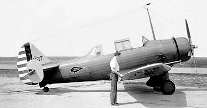
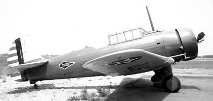
When the modifications were complete, the Air Corps ordered 42 (36-028 to 36-069) under the company design number NA-19; the Air Corps called it the BT-9 (basic trainer, type 9). The first production model was flown on April 15, 1936.
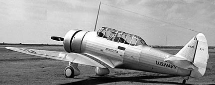
The Navy or¬dered 40 (0910-0949) of them after the existing engine was replaced with a 600hp P&W R-1340 version. That 1937 model was designated the NJ-1 (NA-28, N for trainer and J for North American). The last one was temporarily powered with a 1000hp Ranger XV-770 as NJ-2.
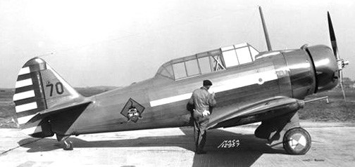
The 40 BT-9As (NA-19A) armed version for Reserve units that followed introduced a fixed forward gun (with gun camera) and a trainable gun in the rear cockpit. Forty were built in 1936, 36-088 to 36-127.
Only small changes were made in the 117 BT-9Bs and 67 BT-9Ds. 117 BT-9B (NA-23) were built in 1937 (37-115 to 37-231) with one modified with new wings and tail as the BT-9D (NA-26) in 1938.
The 1937 BT-9C (NA-29) was an armed version of which sixty-seven were built (37-383 to 37-415). One was modified as the Y1BT-10.
One BT-9C, 37-383, was repowered with a 600hp P&W R-1340 in 1938 as the Y1BT-10 (NA-29).
The Australian Commonwealth Aircraft Corporation was formed in 1936 by several of the largest industrial concerns in Australia. To gain manufacturing experience, it had been decided to acquire a licence to produce an aircraft suitable for advanced training and as a replacement for RAAF Hawker Demons. An Australian Air Board Technical Commission visited the USA and evaluated the North American NA-16, ordered into production for the USAAC as the BT-9 (NA-19) basic trainer.
At the time of the Australian Commission’s visit, North American was working on a development of the BT-99 with a 600 hp Pratt & Whitney R-1340, retractable undercarriage and armament provision as a basic combat trainer. Designated NA-26, this aircraft fulfilled the Australian requirements, although there was disagreement over the need for retractable undercarriage.
As a result, two versions of the A-26 were offered to the Australians, the NA-32 (NA-16-1A) with fixed undercarriage, and the NA-33 (NA-16-2K) with a retractable undercarriage, and in 1937, negotiations for manufacturing rights in both the NA-32 and NA-33 were completed, and an order placed for one of each.
The NA-32 was completed in July 1937, although it was not taken on charge by the RAAF until 8 November 1938, and by that time, the NA-33 / NA-16-2K, which had been completed in September 1937 and taken on charge by the RAAF on 2 February 1938, had already been selected for Australian production.
The NA-16-2K was with a few subtle changes in design to suit it more closely to RAAF requirements and Australian operating conditions, these including a reinforced sub-structure consistent with the rigors of the bombing role and improved offensive/defensive capabilities by the inclusion of 2 x 7.7mm machine guns as opposed to the NA-16’s sole gun.
With the changes, the NA-33 was ordered into production for the RAAF as the A20, the Commonwealth Aircraft Corporation applying the designation CA-1 to the type, and the name Wirraway being adopted. Production of the initial aircraft was handled out of the Commonwealth Aircraft Corporation (CAC) facility at Fisherman’s Bend in Melbourne, Victoria in 1938.
In 1938, Noorduyn acquired the manufacturing rights to the BT-9.
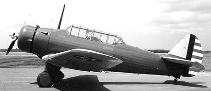
The basic type was then improved with the flying surfaces of the BC-lA and a metal-covered fuselage to produce the BT-14, of which 251 were built with the 336-kW (450-hp) Pratt & Whitney R-985-25 radial. Some 27 were later converted to BT-14A standard with the 298-kW (400-hp) R-985-11 engine.
Concurrently, the French ordered 230 of the BT-9/BT-14 models and called them Tomcats. When France was overrun by the Germans in 1940, Tomcats not yet delivered were given to the Royal Canadian Air Force and designated Yale Mark Is.
BT-9 (NA-19)
Engine: R-975-7 radial, 298-kW (400-hp)
Wingspan: 42’0″
Length: 27’7″
Useful load: 1157 lb
Max speed: 170 mph
Cruise speed: 147 mph
Range: 880 mi
Seats: 2
NJ-1
Engine: Pratt & Whitney R-1340, 373-kW (500-hp)
BT-9A
BT-9B
Powerplant: l x Wright 8-975-7, 298kW (400 hp)
Span: 12.8m (42 ft)
Length: 8.41 m (27ft 7in)
Armament: 2 x 7.62-mm (0.3-in) mg
Max T/O weight: 2028 kg (4,471 lb)
Max speed: 170 mph at sea level
Operational range: 882 miles
Seats: 2
BT-9D
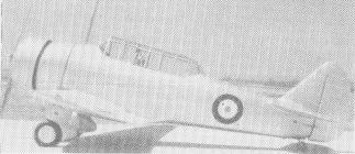
BT-14 / Yale Mk I
Engine: Pratt & Whitney R-985-25, 336-kW (450-hp)
BT-14A
Engine: R-985-11, 298-kW (400-hp)
NA-64 Yale
Engine: Wright R-975-E3 Whirlwind, 440 hp
Wing Span: 42ft 4in
Length: 27ft 11in
Speed: 170mph (273km/h)