Arriving in small numbers in the ranks of the V-VS to witness the mass devastation of the summer of 1941, the Petlyakov Pe-2 was destined to become the best Soviet light bomber of World War II. The aircraft was derived from V.M. Petlyakov’s VI-100 pressurized high-altitude twin-engined interceptor, which displayed a phenomenal top speed of 623km/h at 10,000m, had a crew of two and was powered by 820kW M-105R V-12 engines.
The VI-100 first flew on 7 May 1939. With the approach of war in Europe the V-VS made urgent requests for dive-bomber aircraft, and to this end the design bureau adapted the VI-100 fighter by removing the TK-3 high-altitude turbo-chargers, fitting standard M-105R engines, lattice type dive-brakes, and giving the tailplane pronounced dihedral to increase stability. Two prototype PB-100 (pikiruyushchn bombardirovshchik, or dive-bomber) aircraft were built with these items installed in addition to an extensively glazed nose and defensive armament. This type became the Petlyakov Pe-2 light bomber and dive-bomber. The crew of three (pilot, bombardier and air-gunner) sat under a long glazed canopy with 9mm armour protection. Initial armament consisted of two fixed 7.62mm ShKAS guns in the nose, one in the dorsal station, and a fourth in the ventral aimed by a 120° vision periscope. The M-105R engines drove three-bladed VISh-61 propellers. The aircraft proved to be fast, highly manoeuvrable, but was guite demanding to novice pilots under asymmetric conditions.
By the time of the German invasion in June 1941 some 458 Pe-2s had been produced from the factories, but it is suspected that deliveries to service units was tardy. Certainly, even by September 1941 the numbers of Pe-2s in front-line units were few. Colonel General I.S. Konev’s Western Front had only five in commission with which to stem the German assault on Moscow, and the establishment of Pe-2s with the Bryansk and Kalinin Fronts was even lower. Although limited in numbers, Pe-2s contributed to the victories of the Soviet winter offensive of 1941-2, and were seen in increasing numbers during the defensive battles at Leningrad, Kharkov, Rostov, and in the Stalingrad campaign.
Late in 1942 came the improved Pe-2FT with 940kW Klimov M-105PF engines, and a 12.7mm UBT machine-gun in a dorsal turret. The Pe-2I and Pe-2M were fighter-bombers, powered by 1208kW VK- 107A engines. The reconnaissance version was the Pe-2R, whilst a dual-control trainer was termed the Pe-2UT. The aircraft saw distinguished service in every major Soviet campaign from 1941 to 1945, including operations in Manchuria against the Japanese in September 1945.
The Pe-3 was produced specificaly for night fighting and reconnaissance. Powered by two 1310 hp M-105PF engines, the Pe-3 featured a solid nose and a shorter cockpit enclosure with a dorsal turret to the rear, and was in service by 1943.
A total of 11,427 Pe-2s and Pe-3s (the fighter version) was produced.
The Pe-2RD was a version of the Petlyakov Pe-2 bomber with an additional Glushko RD-1 rocket engine (3 kN thrust) mounted instead of a fuselage tail cone. This conversion was a task of a special design bureau led by V. Glushko, based in Kazan, and working on rocket powerplants; Korolev’s post there was deputy chief designer of flight tests. Korolev made full aerodynamic calculations for Pe-2 equipped with RD-1; they indicated that maximum speed at sea level will increase by 82 km/h (and reach 542 km/h), while at 7000 m altitude it will increase by 108 km/h (although all this only for short time). The reworking of one production Pe-2 (No.15/185) into Pe-2RD began in 1943 spring. The nitric acid tanks were mounted in the bomb bay, kerosene tanks in the wing roots; full weight of rocket fuel system was 1050 kg. After many ground fire tests, on October 1, 1943 test pilot Alexander Vasilchenko first time fired rocket engine in the air for 2 minutes. During this time, flight speed increased by 92 km/h. On October 2 the rocket engine was fired already for 4 minutes, and next day the first takeoff with RD-1 working was performed. Later RD-1 was replaced by improved RD-1KhZ, with chemical ignition instead of electric. The tests were held until middle 1945; more than 100 fire flights were done. On May 12, 1945 the rocket engine exploded – aircraft’s empennage was seriously damaged, Korolev himself scorched; but Vasilchenko managed to land successfully.
Pe-2 Engines: 2 x VK-105PF, 920kW Max take-off weight: 8520 kg / 18783 lb Empty weight: 5870 kg / 12941 lb Wingspan: 17.2 m / 56 ft 5 in Length: 12.7 m / 42 ft 8 in Height: 4.0 m / 13 ft 1 in Wing area: 45.5 sq.m / 489.76 sq ft Max. speed: 581 km/h / 361 mph Cruise speed: 480 km/h / 298 mph Ceiling: 8800 m / 28850 ft Range w/max.fuel: 1200 km / 746 miles Armament: 3 x 12.7mm machine-guns, 2-4 7.62mm machine-guns Bomb load: 600-1000kg Crew: 2
Pe-2 Engines: 2 x Klimov VK-105R, 1100 hp Wingspan: 56 t 4 in Length: 41 ft 4 in Empty weight: 12,900 lb Loaded weight: 18,730 lb Crew: 2 Max speed: 335 mph at 16,400 ft Service ceiling: 29,520 ft Normal range: 1200 mi Armament: 1 x 12.7mm Beresin mg / 4 x 7.62 mm ShKA5 mg Bombload: 2200 lb
Pe-2RD Wing span: 17.60 m Length: 12.60 m Wing area: 40.50 sq.m Empty weight: 6044 kg Normal takeoff weight: 8200 kg MTOW: 9215 kg (with two 500-kg bombs external Maximum speed: 650 km/h Maximum speed at sea level: 542 km/h Range: 1200 km Service ceiling: 9000 m Takeoff run: 446 m (with RD-1 fired): 70 m shorter than ordinary Pe-2
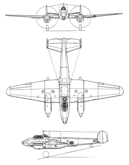
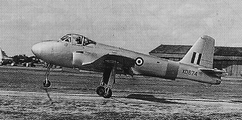
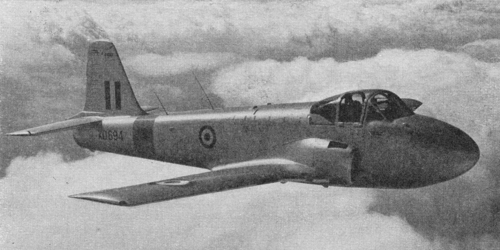
A gas turbine development of the Provost, Jet Provost first flew on June 26 1954, powered by a 1,640 1b. Armstrong Siddeley Viper ASV.5 jet engine. Initially the Jet Provost appeared without a dorsal fin, which was fitted for a while and then removed and replaced by a long ventral fin. Another modification was the sweeping forward of the leading edge wing roots just outboard of the cheek intakes.
After trials, it went to No. 2 Flying Training School at Hullavington for the first all-through (Jet Provost to Vampire) jet flying training course. Production deliveries began in 1959.
Early versions had the prototypes long, stalky undercarriage, but from the 11th aircraft a shorter one was introduced.
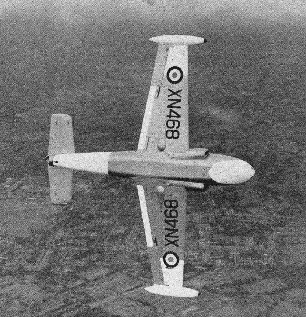
The T.3 was the basic trainer for the Royal Air Force until the mid-1970s, when the up-graded T.4 was introduced.
The Jet Provost T.3, together with the more powerful T.4, with an up rated Viper ASV.11 with 2,500 lb thrust, for night, instrument and formation flying, plus aerobatics, served with the RAF, the T.4 entering service in 1961.
T.3
T.4
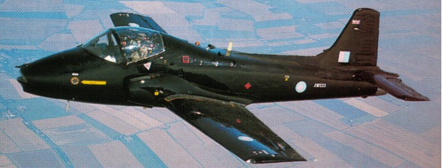
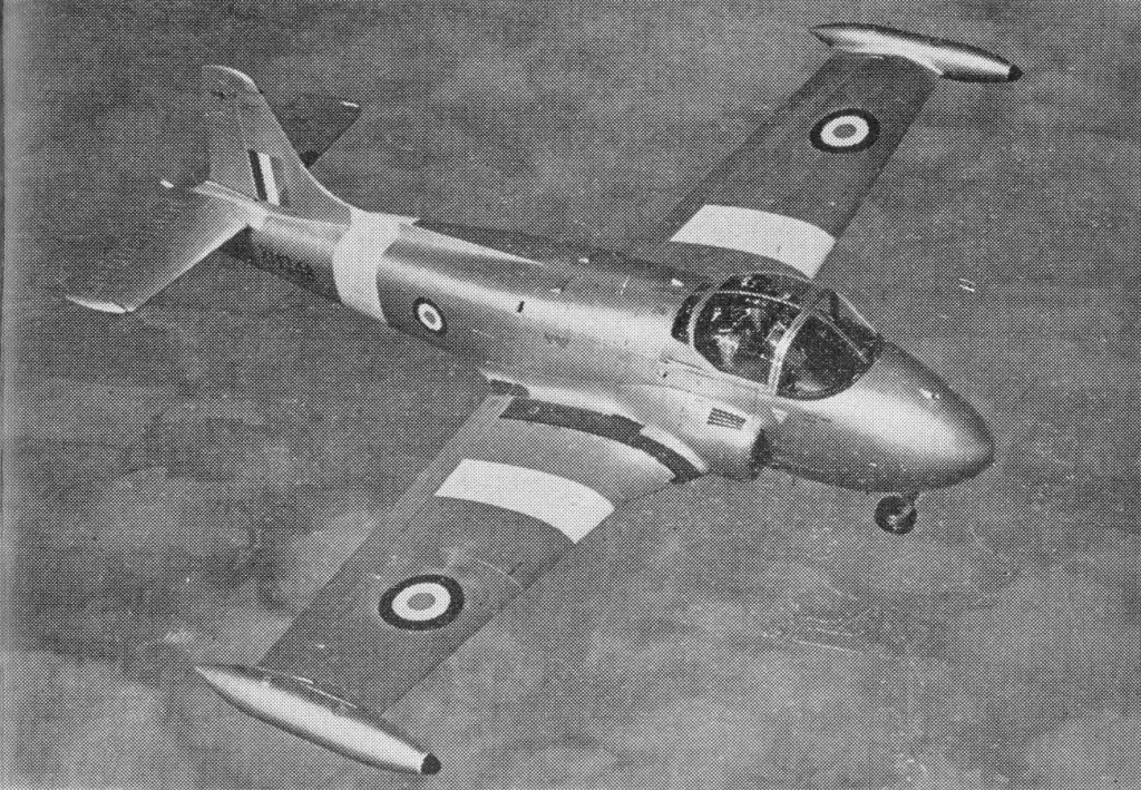
In 1964 the original designers of the Jet Provost responded to the need for a pressurised version and began private work on the design. The Jet Provost T5 differed externally from earlier versions by a re-designed hood and a more bulbous shape to accommodate the pressurised cockpit.
The prototype T5 made its first flight on 28 February 1967. A total of 110 Jet Provost T5s were produced for the Royal Air Force and the first was handed over to the Central Flying School on 3 September 1969. Between 1973 and 1976, ninety-three were modified by an upgrade in avionics equipment and became T5As.
The rough grey coating on the wing of the aircraft was applied in order to break up the smooth airflow and give an early indication of the onset of a stall as the T5’s original clean wing design gave the pilot little prior warning.
Export versions were the T.51 and 52.
The T.5 was further developed into the BAC 167 Strikemaster.
T.4 Engine: Bristol Siddeley Viper 201, ASV8 or ASV11, 2500 lb TO dist: 1030 ft Ldg dist: 1415 ft Time to 30,000ft: 13.3min Wing span: 36 ft 11 in (11.25 m) Length: 32 ft 5 in (9.88 m) Height: 10 ft 2 in (3.11 m) Wing area, 213.7 sq.ft (19.8 sq.m) Empty wt: 4,650 lb (2 110 kg) Max TO wt: 7400 lb (3356 kg) Max speed, 411 mph (661 kph) at 20,000ft (6096 m) Cruise, 280 mph (451 kph) Initial climb, 3,950 fpm. (20 m/sec) Range: 1075 km / 668 miles Crew: 2
T.4A
T.5 Engine: RR Viper 201, 2500 lb thrust Length: 33.99 ft / 10.36 m Height: 10.171 ft / 3.1 m Wingspan: 35.335 ft / 10.77 m Wing area: 213.127 sq.ft / 19.8 sq.m Max take off weight: 9122.1 lb / 4137.0 kg Weight empty: 5490.5 lb / 2490.0 kg Max. speed: 382 kts / 708 km/h Service ceiling: 36745 ft / 11200 m Wing loading: 42.85 lb/sq.ft / 209.0 kg/sq.m Range: 782 nm / 1448 km Crew: 2 Armament: 2 MG 7,62FN/550rds, 1000kg (8x ext.)
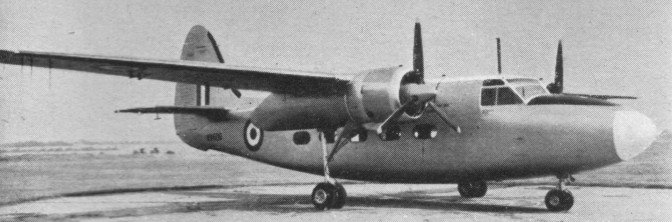
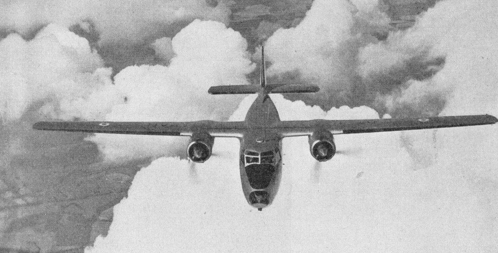
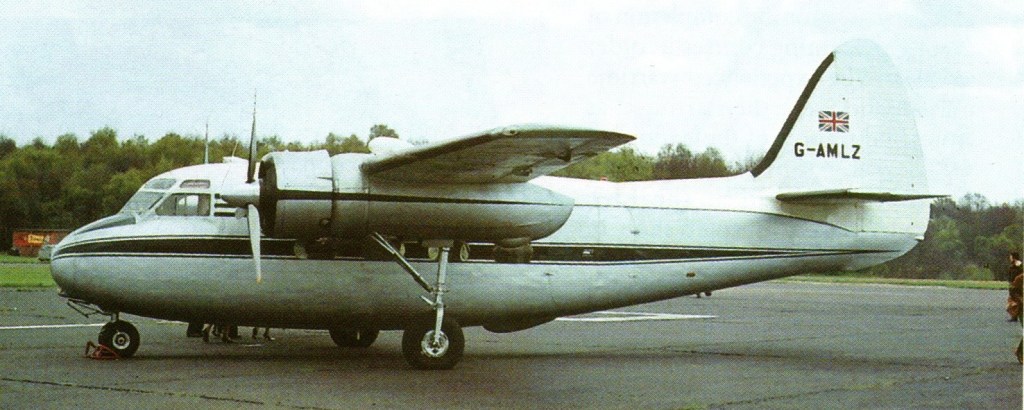
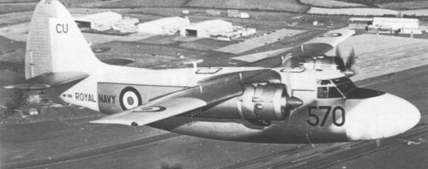
The Percival Pembroke was a British high-wing twin-engined light transport aircraft built by the Percival Aircraft Company, later Hunting Percival.
The Pembroke was a development of the Percival Prince civil transport. The Pembroke is basically an eight seat Service transport developed from the Prince 3 and Sea Prince, with increased span and rearward facing passenger seats. The prototype flew on 21 November 1952.
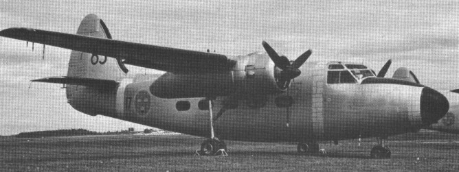
Production for the RAF and the Air Forces of Belgium, Southern Rhodesia and Sweden was complete in early 1958. Sixteen Pembroke C.52s were obtained by the Swedish Air Force in 1955 and designated Tp-83s.
The Pembroke C.1 were used as eight seat communications aircraft and a version with a clear-view nose and camera stations in the main cabin fr air survey and photography was in service in the Belgian Air Force in 1956.
Belgian Air Force Pembroke
Pembroke C.52
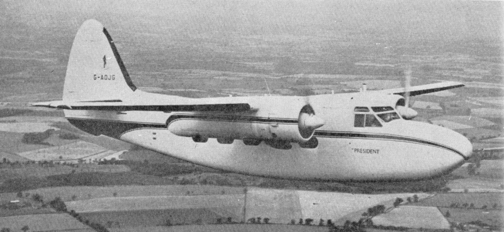
A civil version known as the Prince Series 5 was under development. Appearing as the President, the first airline order for Presidents was placed in 1957 by a Spanish local operator.
Percival Pembroke C Mk.1 Engine : 2 x Alvis Leonides 127, 533 hp Length : 46 ft 0 in / 14.02 m Height : 16.076 ft / 4.9 m Wingspan : 64 ft 6 in / 19.66 m Max take off weight : 13503.4 lb / 6124.0 kg Max. speed : 162 kt / 300 km/h Service ceiling : 21982 ft / 6700 m Range : 999 nm / 1850 km Crew : 2 + 8
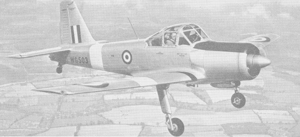
Designed by Percival Aircraft before it became part of the Hunting Group in 1954, the Provost was selected as the standard RAF trainer in the early 1950s having been designed to fulfil the requirements of specification T.16/48. A cantilever low wing monoplane with fixed tailwheel landing gear and powered by an Alvis Leonides 126 engine, it provided side by side seating for instructor and pupil.
The Percival P.56 Provost was the last piston-engined basic trainer used by the RAF. The prototype WE522 first flew on 23 February 1950 and was powered with a Cheetah 17 radial engine, as was the second prototype.
The third prototype was powered with the tightly cowled Alvis Leonides nine-cylinder radial. Both the earlier aircraft were re-engined and all the production T Mk 1 aircraft used the Alvis engine. This 11.9-litre supercharged engine is a smaller than usual 550-hp radial; the higher power is achieved by running at high revolutions (3,000 rpm) and +8 lb/sq inch of boost. Cruise power of 330 hp is at 2,600 rpm at 11,000 ft (RAF settings). A three-blade constant speed propeller is driven through a reduction gear, and it has side-by-side seating under a sliding canopy.
In 1953, the RAF introduced two new trainers into service, the piston engined Percival Provost T.1, which replaced the Prentice, and the jet powered DH Vampire T.11 which replaced the Harvard and the Meteor T.7 with the Advanced Flying Schools. As the RAF Prentice replacement, the Percival P.56, which became the Provost, powered by a 240 hp Cheetah 18 engine, its top speed was 178 mph at 2,500 ft. Entering service under the designation Provost T Mk 1, the aircraft were first delivered to the Basic Training Squadron of the Central Flying School of the RAF at South Cerney.
In armament training form it is fitted with two 7.9 mm. machine guns with 1,200 rounds of ammunition and a camera gun, and carrying three 60 lb rocket projectiles beneath each wing. Despite this load the Provost was rolled with abandon and climbed inverted under the continuous running of its Alvis Leonides engine. Alternative armament of the Provost is two 250 lb. bombs or eight 25 lb. bombs on light series racks or eight 25 lb. bombs plus four 60 lb. R.P.s.
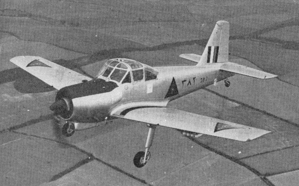
T.Mks.51, 52 and 53 are export versions serving with six air arms. Mks.52 and 53 carry light armament. As the T.53, the type was also supplied to Burma, Iraq and the Sudan, while the T.51 and T.52 were used by Eire and Rhodesia/Zimbabwe.
Iraqi armed Provost
When production ended in 1959, a total of 461 had been built, including a number armed with machine guns and bombs. They also served in the air arms of Sudan, Malaysia and Muscat.
The last active RAF Provost was retired in 1969, some going to training establishments as instructional airframes, with only a few of these eventually reaching civilian operators.
T Mk 1 Engine: Alvis Leonides 126, 550 hp / 410kW Span, 35 ft 2 in (10.9 m) Length, 28 ft 8 in (8.8 m) Height: 3.70 m / 12 ft 2 in Wing area, 214 sq.ft (19.8 sq.m). Empty weight, 3,350 lb (1521 kg) Max take off weight, 4,400 lb (1996 kg) Max speed, 174 kt / 200 mph / 322 kph at 2,300 ft (700 m) Cruise, 177 mph (283 kph) at 11,500 ft (3510 m) Initial climb, 2,200 fpm (11.18 m/sec) Service ceiling: 7620 m / 25000 ft Range, 650 mls (1046 km) Crew: 2
The 1948 Percival Prince was a British light transport of the early post-war period. It was a twin-engine, high-wing, cantilever monoplane of all-metal stressed-skin construction; the undercarriage was of retractable, tricycle type. The design of the Prince followed on from the solitary Merganser.
Further development of the type led to the Survey Prince survey aircraft and the Sea Prince. The official designation of the Naval communications version of the Percival Prince was given as Sea Prince C.2.
August 1950
An improved version of the Prince 3 with an increased wingspan and engine and undercarriage modifications was developed for the Royal Air Force as the Percival Pembroke. The Percival Prince 5 the transport variant of the Pembroke.
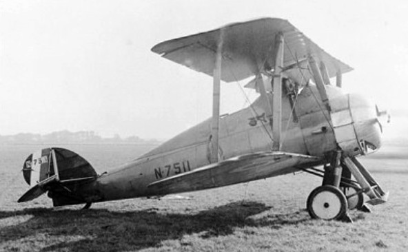
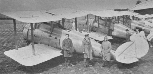
Two-seat carrier-borne spotter and reconnaissance biplane of 1917 powered by a 171kW Bentley B.R.2 engine. One hundred and fifty served with the FAA from 1919 until 1926.
A deck landing aircraft of the Japanese navy.
Engine: 1 x Bently B.R.2, 172kW Max take-off weight: 1177 kg / 2595 lb Empty weight: 602 kg / 1327 lb Wingspan: 8.99 m / 30 ft 6 in Length: 7.95 m / 26 ft 1 in Height: 3.2 m / 11 ft 6 in Wing area: 31.21 sq.m / 335.94 sq ft Max. speed: 175 km/h / 109 mph Ceiling: 4420 m / 14500 ft Armament: 1 x 7.7mm machine-gun
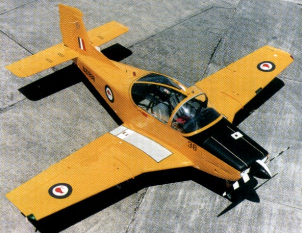
The CT-4 Airtrainer was born out of two situations that occurred in the early 1970’s. Firstly the failure of the T6/24 Airtourer to meet the Royal Australian Air Force (RAAF) requirement for a basic trainer. Secondly the foresight of the AESL management of the time to exercise an already held option on the production rights to the Victa Aircruiser and adapt it into what we know as the CT-4 Airtrainer.
Development included a jettisonable clamshell canopy, revised seating and interior with side-by-side and optional third seat in the rear, and structural strengthening for aerobatic work. The wings are constructed separately, and during their installation to the fuselage are joined by splicing the two protruding main spars at 6 deg 4 min of dihedral on the top of the spar and 3 deg incidence at the root. Conventional control surfaces are utilised, with electrical spring bias trimming devices provided for the rudder and elevator and fixed tabs for the ailerons. Flaps are electrically operated and can be set at any position, while the fixed under¬carriage has a steerable nosewheel and the wheel brakes are toe operated.
Powered by a 210 hp Continental IO-360-H and the CT-4 was designed for aerobatics of +6 to -3g.
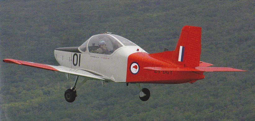
The first CT/4 Airtrainer s/n 001 first flew on 23 February 1972 (ZK-DGY).
ZK-DGY
The second prototype was built to refine the design. The second, c/n 002, was the only single-control model ever made. The two prototypes were the only Airtrainers made under the AESL banner.
AESL secured a RAAF contract to supply 37 aircraft. This order was followed by another from the Royal Thai Air Force for 24 aircraft.
These orders prompted the merger of AESL with Air Parts (NZ) Ltd and with the involvement of the New Zealand Government, New Zealand Aerospace Industries was formed.
The RAAF order followed the RTAF order down the production line also as CT-4As the first in December 1974 and continuing throughout 1975, ending with s/n 063.
CT-4A
A further order from a Swiss company named Breco had been secured for 14 aircraft (c/n 064 to c/n 077) and these immediately followed the last RAAF Aircraft down the line. These aircraft were designated CT-4B but were not the same as the civil CT-4Bs that were produced at a later date. They were in fact destined for Rhodesia (Zimbabwe) which was UN sanctioned at the time and the NZ Government prevented their export and consequently they were never delivered (although paid for).
The Royal New Zealand Air Force was next to sign up for CT-4s with an order for 13 aircraft. These were produced in 1976 ending with s/n 090. Although initially they were to be CT-4D models the aircraft were data plated as CT-4B, however technically they were neither as they were not built to the Type Certificate but to a RNZAF specification. The CT/4B designation described a higher all up weight requirement by the RNZAF to accommodate additional avionics.
Then the orders had run out and continuous production ceased at s/n 090.
When NZASIL announced the termination of CT-4 production the RNZAF in 1978 ordered a further 6 aircraft as attrition airframes.
In 1981 the RAAF, looking to expand their fleet of CT-4A Airtrainers, opted to purchase the Breco CT-4B aircraft that had been in storage since manufacture. These aircraft went down the production line once again retaining their original serial numbers to be converted from the Breco CT-4B specification into the RAAF CT-4A specification. The last aircraft was completed in May 1982 and that seemed to be it for CT-4 production.
With the purchase of NZAI by the Pacific Aerospace Corporation in 1982, the turbine project was taken out of the filing cabinet and re examined. Initially mooted was the CT4/CR featuring the Allison 250 B17 turboprop engine and a redesigned wing to accommodate a retractable undercarriage. Subsequently it was decided to build an intermediate stage, the fixed gear CT/4C.
With no airframes on hand to modify for the project, PAC approached the RNZAF and NZ1940 c/n 066, written off and reduced to spares was obtained. A 250 hp Allison turboprop, fitted with a PAC designed and built oil and fuel system to enable up to 30 seconds of inverted flight, was installed on 21 December 1990. Up front was a three bladed variable pitch Hartzell propeller.
On 21 January 1991 the CT/4C was test flown for the first time, by chief test pilot John Muir accompanied by Murray McGregor. Downrated to match the 210 hp of the CT/4B, the Allison was able to maintain its horse power through to 5000 feet. The CT/4C rotated at 60 knots and climbed away at 90 kts. The engine horsepower was increased to 300. At 300 hp John Muir described the aircraft as very quiet with more noise coming from the slipstream than the engine. Cruise on 300hp proves out at 165 knots (25 knots above the CT/4B on 75 percent power) and has a 2000 foot per minute climb rate at 105 knots. The stall is clean 58 knots, full flaps 48 knots. The engine uses about 80 litres/hour.
Production resurfaced under the PAC banner in 1990 when the RAAF decided to civilianise it’s basic training and sell off the majority of CT-4A Airtrainers.
In 1990, PAC proposed one major change to the new batch of Airtrainers; introducing an inverted oil system to permit extended inverted flight, a modification developed from the Christen system implemented by the RNZAF. The change is to be incorporated by Teledyne Continental at the factory level as the IO 360-HB9.
The contract to provide this training was awarded to BAe/Ansett in NSW (later BAe Systems Australia) who in 1990 ordered 12 CT-4 Airtrainers to undertake the task. These were produced from ex-RNZAF aircraft as civil CT-4B models during 1991 and 1992. The RTAF, aware that the CT-4 was back in production, placed an order for 6 CT-4B models and these were produced after the BAe/Ansett airframes taking total production to-date to 114.
During this same period the development of the CT-4E was undertaken in the hope of securing an USAF contract. Using ex Breco and ex RAAF airframe s/n 065 the development was successful, but the contract hopes not.
The CT/4E incorporates a larger engine and three-blade Hartzell prop. To compensate for the heavier 300 hp Textron Lycoming AEIO-540-L1B5 engine and Hartzell 3-blade variable pitch prop, the wings were located further forward. The first CT/4E flew on 16 November 1991 and entered production in 1998.
Nothing further happened until 1996 when under the new Aeromotive ownership of PAC the Aeromotive Group was successful in securing a contract to lease of 13 CT-4E Airtrainers to the RNZAF as NZ1985 to NZ1997.
Production recommenced with a new serial number sequence for the CT-4E starting at s/n 200. The first CT/4E delivery to the RNZAF on 28 August 1998 and the last delivered in June 1999.
The RTAF placed an order for 12 CT-4E aircraft and these were produced during 1999 and 2000. In the middle of the RTAF order s/n 216 was reconfigured from RTAF specifications and is operated by Aerotec Flight Training in Queensland, Australia.
The RTAF ordered a further 4 CT-4Es and these were produced in 2001 followed in 2002 by 2 Aircraft for DSTA in Singapore.
All models were certified under NZ CTA A-10.
CT/4B
As of 2004 total production of the CT-4E had reached 32 (c/n 200 to c/n 231). In addition to 13 RNZAF and 16 Thai examples, one went to a private buyer in Israel and two to the Defence Science and Technology Agency Singapore.
Production Data CT-4 qty 2 s/n 001 – 002 S/n 001 was retained as a demonstrator and then eventually sold to a NZ syndicate. S/n 002 was the only single control CT-4 ever built. It was gifted to the King of Siam (Thailand). CT-4A qty 61 s/n 003 – 063 S/n 003 – 026 sold to RTAF S/n 027 – 063 sold to RAAF (most on Australian civil register today. 3 in USA) CT-4B qty 14 s/n 064 – 077 Not the same as a civil CT-4B model. S/n 064 – 077 sold to Breco and never delivered. Converted to CT-4A model and sold to RAAF. S/n 065 owned by PAC as ZK-PAC (prototype CT-4E). CT-4B qty 19 s/n 078 – 096 Not technically CT-4B although data plated as such. S/n 078 -096 sold to RNZAF. Traded in on CT-4E models in mid 1990s. Converted by Aeromotive to civil CT-4B and most operated by BAe Systems Australia. CT-4B qty 18 s/n 097 – 114 The only civil CT-4Bs ever produced. S/n 097 – 108 sold to BAe/Ansett. S/n 109- 114 sold to RTAF. CT-4E qty 40 s/n 200 – 240 S/n 200 – 212 sold to Aeromotive (leased to RNZAF) S/n 213 – not produced. S/n 214 -215 sold to RTAF. S/n 216 – sold privately in Israel. S/n 217 – 230 sold to RTAF. S/n 231 – 232 sold to DSTA Singapore. S/n 233 – 240 sold to RTAF S/n 241 – Company Demonstrator
CT-4 Model Development CT-4C – Allison 250 powered Turbine variant developed but not certified on loan RNZAF s/n 088, returned to RNZAF as CT-4B. CT-4CR – Allison 250 powered turbine variant with retractable undercarriage. CT-4D – Original RNZAF model designation. Later revived as a Textron Lycoming TIO-360 powered variant.
Specifications: CT-4
CT-4A Engine: Teledyne Continental IO 360 H, 210 hp / 156.6 kW Wingspan: 26 ft / 7.92 m Length: 23 ft 2 in / 7.05 m Height: 8 ft 5 in / 2.59 m Empty weight: 1520 lb / 690 kg Loaded weight: 2350 lb / 1070 kg Max speed: 180 mph / 290 kph Max range: 808 mi / 1300 km Service ceiling: 17,900 ft / 5456 m
CT-4B Engine: Teledyne Continental IO-360-H, 210 hp Wing span: 26 ft (7.92m) Length: 23.16 ft (2.59m) Wing area: 129 sq.ft Fuel cap: 320 lbs useable Empty wt: 1699 lbs MTOW: 2650 lbs Max aerobatic wt: 2500 lbs Vne: 207 kts Maximum speed: 180 mph (290 kph) VA: 141.5 kts Stall: 58 kts Cruise 65%: 150 mph Endurance 65%: 4.86 hr Maximum range: 808 miles (1300 km) Useful load: 742 lb (337 kg) ROC: 1350 fpm Service Ceiling: 17,900 ft (5456 m)
CT-4C Engine: Allison 250B17D turboprop
CT-4E Engine: Lycoming AEIO-540L1-B5, 300 hp Wing Span: 26.0 ft / 7.92 m Area – Wing Gross: 129.0 sq.ft / 39.32 sq.m Length Overall 23.48 ft / 7.16 m Height (ground to top of fin): 8.50 ft / 2.59 m Basic Empty Weight: 1780 lb / 807 kg Max. Landing Weight: 2600 lb / 1180 kg Stowage Capacity (Utility Category): 160 lb / 73 kg Stowage Capacity (Aerobatic): 100 lb / 45 kg Maximum Fuel: 322 lb / 150 kg Fuel Capacity: 44 Imp Gal / 199 lt Useable fuel: 198 lt Fuel Consumption: 14 Imp Gal/hr / 65 lt/hr Va Manoeuvring Speed: 144 kt Vc Design Cruising Speed: 150 kt Vd Design Diving Speed: 209 kt Vs Stalling Speed – No Flap: 60 kt Vsf Stalling Speed – With Full Flap: 45 kt ROC 100 kt: 1500 fpm Range: 520 nm / 836 km Take off Ground Roll: 600 ft / 183 m Landing Run: 553 ft / 168 m Rate of Climb: 1830 fpm Aerobatic Flight (Flaps Up): +6.0g / -3.0g Wing Loading: 20.2 lb/sq.ft Power Loading (at MAUW): 8.7 lb/hp Area – Flap: 22.60 sq.ft / 6.89 sq.m Area – Aileron: 11.56 sq.ft / 3.52 sq.m Area – Elevator: 16.7 sq.ft / 5.09 sq.m Area – Fin & Rudder: 12.69 sq.ft / 3.87 sq.m Cabin, Inside Width: 3.64 ft / 1.10 m Cabin, Inside Length: 8.93 ft / 2.72 m Cabin, Inside Height: 3.83 ft / 1.17 m Wheel Base: 5.45 ft / 1.66 m Wheel Track: 9.75 ft / 2.97 m
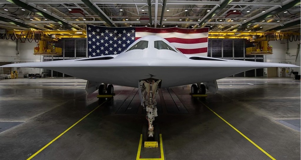
B-21 in a hangar at Plant 42 in Palmdale, California
The Northrop Grumman B-21 Raider is an American strategic bomber under developed for the United States Air Force (USAF) by Northrop Grumman. As part of the Long Range Strike Bomber (LRS-B) program, it is a long-range, stealth intercontinental strategic bomber for the USAF, able to deliver conventional and thermonuclear weapons.
The classified Long Range Strike Bomber (LRS-B) program began in 2011, and the Air Force issued a request for proposal to develop a LRS-B aircraft in July 2014. A development contract was awarded to Northrop Grumman in October 2015. Boeing and Lockheed Martin, who submitted losing bids for the project, filed bid protests; in October 2016, the Government Accountability Office (GAO) rejected the challenges and sustained the USAF’s decision to award the LRS-B contract to Northrop Grumman. The GAO report revealed that cost was the deciding factor in selecting Northrop Grumman over the Boeing-Lockheed Martin team.
In March 2016, the USAF announced seven tier-one suppliers for the program: Pratt & Whitney, BAE Systems, Spirit AeroSystems, Orbital ATK, Rockwell Collins, GKN Aerospace, and Janicki Industries.
Many aspects of the B-21 program are highly classified; the program is designated as a special access program. The Congressional Research Service noted in a report that the B-21’s technical details and specifications, such as speed, enabling systems, “size, required stealth, structure, number and type of engines, projected weapons, and onboard sensors remain classified” although some information about various other aspects of the program have been made public since 2015. A 2015 media report said that the Air Force wanted the bomber to also function as an intelligence collection platform, battle manager, and interceptor aircraft. In 2016, then–Secretary of the Air Force Deborah Lee James said that the B-21 would be a “fifth-generation global precision attack platform” with networked sensor-shoot capability. Northrop Grumman described the B-21 at its 2022 “unveiling” as “the world’s first sixth-generation aircraft.”
The F-35 program manager Chris Bogdan said the B-21’s engines would be similar enough to the F-35’s Pratt & Whitney F135 engine to reduce its cost.
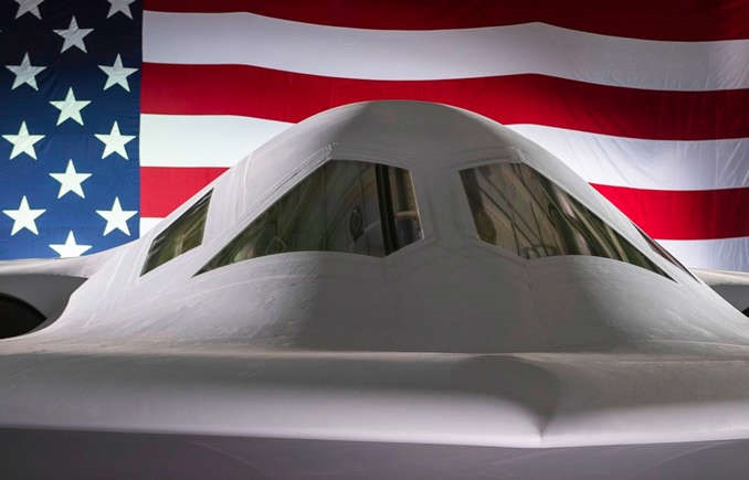
In January 2020, Air Force officials released new B-21 renderings and Northrop Grumman, showing the distinctive flush and blended inlets and the two-wheel main landing gear design. The drawing appeared to show a smaller, lighter aircraft than the B-2.
The program completed its critical design review in December 2018.
In September 2022, the USAF announced that the B-21 was to be unveiled in early December 2022 in Palmdale, California. The bomber was first shown to the public at a 2 December 2022 ceremony at Northrop Grumman’s production facilities in Palmdale, California. At the unveiling, Northrop CEO Kathy Warden said that the B-21 is designed with modular, open systems architecture to allow easy upgrades, and potentially, the ability to export components to foreign buyers. Warden said that the B-21’s internal operations were “extremely advanced compared to the B-2” and that the B-21 was slightly smaller than the B-2, with a longer range.
While the potential for an uncrewed flight was not mentioned during the ceremony, a US Air Force spokeswoman said the aircraft was “provisioned for the possibility, but there has been no decision to fly without a crew”.
At the 2016 Air Warfare Symposium, Air Force officials announced that the LRS-B would be formally designated “B-21” because the aircraft would be the 21st century’s first bomber. In September 2016, Air Force officials announced that the B-21 would be named “Raider” in honor of the Doolittle Raiders. The then-remaining survivor of the Doolittle Raiders, retired Lt. Col. Richard E. Cole, was present at the naming ceremony at the Air Force Association conference.
The head of the Air Force Global Strike Command said he expected the service would place an initial order for 100 B-21s and build up to a full fleet of 175 to 200. Two USAF studies suggested that Air Force could increase its initial purchase from 80-to-100 to 145 aircraft. Initial operating capability (IOC) was expected to be reached by 2030.
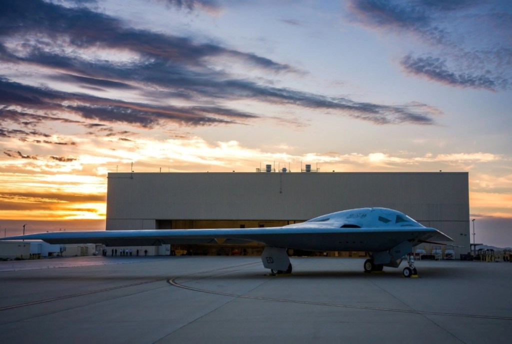
Assembly of the B-21 takes place at the United States Air Force Plant 42 near Palmdale, California, at the same facility Northrop Grumman used during the 1980s and 1990s to build B-2 bombers. In January 2017, Northrop Grumman was awarded a $35.8 million contract modification for a large coatings facility at Plant 42, to be completed by the end of 2019; the contract announcement did not specifically mention B-21, but the facility was likely meant for B-21 stealth coating. Because the program is classified, officials released very little information about it. By the summer of 2019 it was reported that construction of the first unit was underway. In early 2021, several media outlets reported that as completion of the first B-21 approached, construction on the second unit had begun.
By February 2022, six B-21s were under construction. The first B-21 was moved to a calibration facility the following month. About 5,000 Northrop Grumman employees worked on the program as of December 2022.
As of 2022, the B-21 was expected to enter service by 2026 or 2027. It is to complement and eventually replace the Northrop Grumman B-2 Spirit, but not the Boeing B-52 Stratofortress bombers.
In December 2022, the cost of a B-21 aircraft was estimated to be US$700 million; at the time, Air Force officials estimated that the cost to develop, purchase, and operate a fleet of 100 B-21s over a 30-year period would be at least $203 billion.
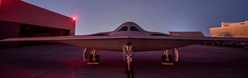
The first B-21 at Northrop’s Plant 42 in Palmdale, California, 29 November 2022.
Maintenance and sustainment of the B-21 will be coordinated by Tinker Air Force Base, Oklahoma, while Edwards Air Force Base, California, will lead testing and evaluation. In March 2019, Ellsworth was selected as the base to host the first operational B-21 unit and the first training unit.
In May 2022, the USAF announced that they expected first flight of the B-21 to take place in 2023.
The new bomber has stayed on cost and on schedule. The Air Force has set a $500 million ceiling for the unit cost in 2010 dollars; in 2019, Northrop said the Air Force’s target cost would be just over $600 million, accounting for inflation.
The first new B-21s will be based out of Ellsworth Air Force Base in South Dakota, and formal training will be conducted there as well. Maintenance and sustainment will be handled at Tinker Air Force Base in Oklahoma, while testing and evaluation is being performed at Edwards Air Force Base in California.
B-21, also known as Cerberus, achieved its first flight to Edwards Air Force Base on November 10, 2023.
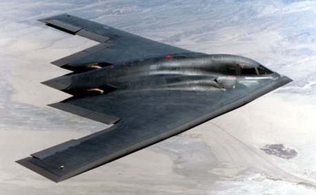
Development of the B-2 was begun in 1978, and in designing the Advanced Technology Bomber (ATB), as the B-2 project was originally known, the Northrop Company decided on an all-wing configuration from the outset. Flying-wing devotees such as Hugo Junkers and Jack Northrop argue that a flying wing will carry the same payload as a conventional aircraft while weighing less and using less fuel. The weight and drag of the tail surfaces are absent, as is the weight of the structure that supports them. The wing structure itself is far more efficient because the weight of the aircraft is spread across the wing, rather than concentrated in the centre.
The B-2 design is a flying wing with straight 40 degree sweep leading-edges and a sawtooth trailing edge. Its centrebody is smoothly contoured into the upper wing surface. The centrebody houses the two-man crew compartment and the two weapons bays, one on each side of the centreline. The cockpit compartment is accessed through a ventral hatch and has large cockpit windows to improve the pilots angular field of view, yet the nose-down view remains very limited. The engines lay outboard the weapon bays in the upper wing surface. The exhausts are positioned forward of the wing trailing edge to reduce heat signature.
Because of the big wing area and wing span, the lift needed per square foot of wing is not as high compared to other designs of the same weight. Therefor the B-2 does not need complex flaps. It operates over a smaller angle of attack.
The all-wing approach was selected because it promised to result in an exceptionally clean configuration for minimizing radar cross-section, including the elimination of vertical tail surfaces, with added benefits such as span-loading structural efficiency and high lift/drag ratio for efficient cruise. Outboard wing panels were added for longitudinal balance to increase lift/drag ratio and to provide sufficient span for pitch, roll and yaw control. Leading-edge sweep was selected for balance and trans-sonic aerodynamics, while the overall planform was designed for neutral longitudinal (pitch) static stability. Because of its short length, the aircraft had to produce stabilizing pitchdown moments beyond the stall for positive recovery. The original ATB design had elevons on the outboard wing panels only but, as the design progressed, additional elevons were added inboard, giving the B-2 its distinctive ‘double-W trailing edge. The flight-control surfaces are operated by a fly-by-wire control system to ensure optimum control responses in this design of relaxed stability intended for positive aerodynamic control at all times, throughout the airframe, emphasis is placed on completely smooth. The wing leading edge is so designed that air is channelled into the engine intakes from all directions, allowing the engines to operate at high power and zero airspeed. In trans-sonic cruise, air is slowed from supersonic speed before it enters the hidden compressor faces of the GE F118 engines.
A stores management processor is in place to handle the B-2’s 22,730kg weapons load. A separate processor controls the Hughes APQ-181 synthetic-aperture radar and its input to the display processor. The Ku-band radar has 21 operational modes, including high-resolution ground mapping. The B-2 lifts off at 260km/h, the speed independent of take-off weight. Normal operating speed is in the high subsonic range and maximum altitude around 15,240m. The aircraft is highly manoeuvrable, with fighter-like handling characteristics.
The US Air Force originally wanted 133 examples, but by 1991 successive budget cuts had reduced this to 21 aircraft.
First revealed in November 1988, the prototype flew on 17 July 1989, and the first production B-2 was delivered to the 393rd Bomb Squadron of the 509th Bomb Wing at Whiteman AFB, Missouri, on 17 December 1993. Northrop delivered 21 B-2A Spirit stealth bombers, achieving initial operational capability with the USAF in April 1997 and full capability with the 715th Bomb Squadron in 1999.
With a crew of two, it is powered by four 19,0001b thrust F 118 GE 100 engines (as used in the F 16) and has a published speed of 0.72 Mach. The multi role bomber is publicised as fuel efficient, able to carry a “substantial bomb load” and with “excellent range”. Unit cost: Approximately US$750 million
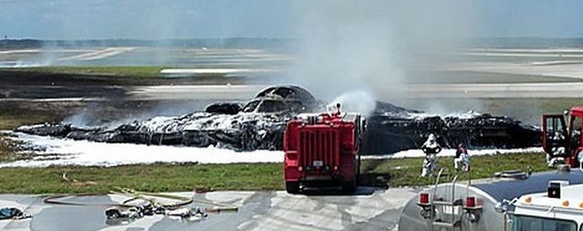
When B-2 89-0127, named the Spirit of Kansas, crashed on takeoff at Andersen Air Force Base in Guam, it immediately became the most expensive accident in USAF history. The crash was determined to have been caused by moisture in the port transducer units which resulted in the distortion of information sent to the aircraft’s air data system. The B-2’s flight control computers calculated an incorrect air speed and angle of attack, causing the nose to pitch-up 30 degrees and sending the aircraft into an unrecoverable stall. The pilots ejected safely, though the Spirit of Kansas was reduced to a $1.4 billion pile of burning wreckage.
Northrop B-2A Spirit Engines: 4 x General Electric F-118-GE-100 turbofan, 17,300 lb / 7,847 kg Length: 69 ft (20.9 m Height: 17 ft / 5.1 m Wingspan: 172 ft / 52.12 m Wing area: 3982.68 sq.ft / 370.0 sq.m Takeoff Weight (Typical): 336,500 lb / 152,635 kg MTOW: 371,000 lb / 168,286 kg Max speed: 475 mph / M0.76 Cruising speed: 516 kt / 955 km/h Ceiling: 50,000 ft / 15,152 m Op radius: 3800 mile / 6115 km Payload: 40,000 lb / 18,144 kg Crew: Two pilots, with provisions for a third crew station
Basic development of the Northrop F-89 Scorpion began during 1945 in response to a general requirement issued by the then US Army Air Force calling for an aircraft capable of a speed of 845 km/h (525 mph) at 10670 m (35,000 if) with a 965-km (600-mile) combat radius and the ability to operate with air-to-air rockets. Although the jet era had already begun, the original requirement called for a propeller-driven aircraft, but most of the six companies which responded submitted proposals based upon the use of jet power. In March of the following year, one of the four Northrop candidates was selected for further development and rewarded with a contract for two XP-89 prototypes on 13 June 1946, flown for the first time on 16 August 1948.
Northrop F-89 Scorpion Article
Initial trials revealed few problems, and the type was ordered into production as the F-89A in 1949. Soon afterwards, the Scorpion began to run into difficulties, most of which centred around inadequate performance; but there was also serious concern about structural integrity and it was decided to suspend production until Northrop had eradicated these failings. In the event, only 11 examples of the F-89A were completed, most of these being emplayed on operational trials, and it was the F-89B which became the first operational model, entering service at Hamilton AFB, California, in June 1951.
A total of 37 F-89Bs was built before production switched to the essentially-similar F-89C. It was at about this time that the Scorpion gained a reputation as ‘the world’s largest vacuum cleaner’, the low-slung engines being prone to damage by objects ingested on takeoff and during taxiing; inlet screens helped to overcome this difficulty.
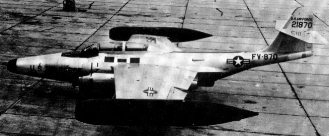
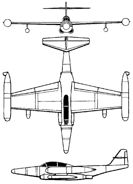
F-89D Scorpion
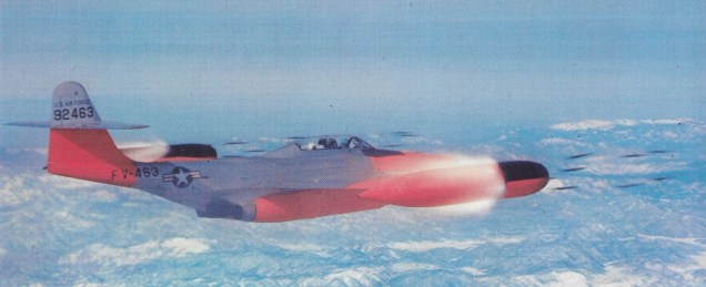
The most numerous sub-type was the F-89D with revised engines and improved fire-control and armament systems, no less than 682 being built by March 1956. The standard fighter equipment with U.S.A.F. in 1955, early F-89A, B and C had six 20 mm. cannon in nose. F-89C could also carry 16×5 in. rockets under wings. They were followed by the rather more heavily-armed F-89H, almost all of the 156 aircraft of this version being accepted in 1956. Subsequently, 350 of the earlier F-89Ds were fitted with a new fire-control system and revised armament in the form of the Douglas MB-i Genie missile, these henceforth being known under the designation F-89Js. The first nuclear-armed interceptor to make its debut, the F-89J began to enter service at Hamilton in January 1957 but enjoyed only a short front-line career, giving way to more sophisticated interceptors like the McDonnell F-101B, Convair F-102A and Convair F-106A in 1960. Many Scorpions did, however, continue to fly with the Air National Guard until 1968.
A total of 1232 were built.
F-89D Engines: 2 x Allison J35-A-35, -33A, -41, -47 afterburning turbo-jet, 3266kg / 5,600 lb Max take-off weight: 19160 kg / 42241 lb Empty weight: 11428 kg / 25195 lb Wingspan: 18.19 m / 59 ft 8 in Length: 16.41 m / 53 ft 10 in Height: 5.36 m / 17 ft 7 in Wing area: 52.21 sq.m / 561.98 sq ft Max. speed: 1024 km/h / 636 mph Ceiling: 14995 m / 49200 ft Range: 4184 km / 2600 miles Armament: 3 x “Falcon” guided missiles, 104 x 70mm missiles Crew: 2
F-89J Scorpion Powerplant: two 3266-kg (7,200-lb) afterburning thrust Allison J35-A-35 turbojets Maximum speed 958 km/h (595 mph) at 10970 m (36,000 ft) Initial climb rate 1573 m (5,160 ft) per minute Service ceiling 15600 m (51,180 ft) Maximum range 1720 km (1,690 miles) Maximum take-off weight 19319 kg (42,590 lb) Wing span 18.19 m (59 ft 8 in) Length 16.33 m (53 ft 7 in) Height 5.36 m (17 ft 7 in) Wing area 52.2 sq.m (562 sq ft) Armament: two MB-i (AIR-2A) Genie nuclear-tipped rockets and 104 FFAR rockets.