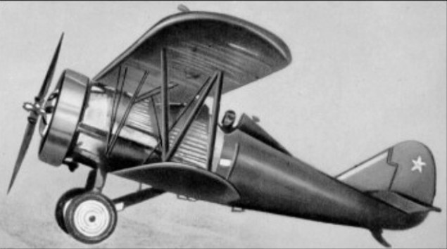
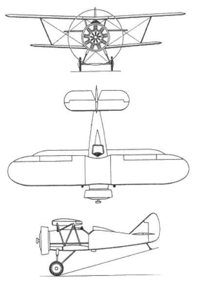
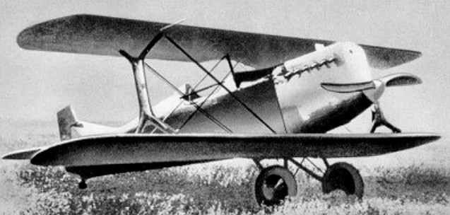
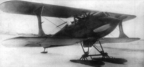
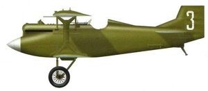
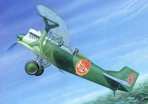
The first prototype of this diminutive single-seat unequal-span biplane flew on 29 April 1930. Power was provided by an imported Gnome-Rhone Jupiter VII radial engine with individual helmet-type fairings over each cylinder head. The second prototype was named Klim Voroshilov after the Soviet Defence-Minister. It had a Jupiter VI radial and was intended for low-level operations. The third and final prototype had a Soviet M-15 radial engine with a ring cowling. In the summer of 1930 seven evaluation aircraft were built, powered by the 358kW M-22 radial – in fact a Russian version of the Jupiter VI. Tests were successful and series production was undertaken. A total of 803 was built and the type formed the main equipment of Soviet fighter units until 1936.
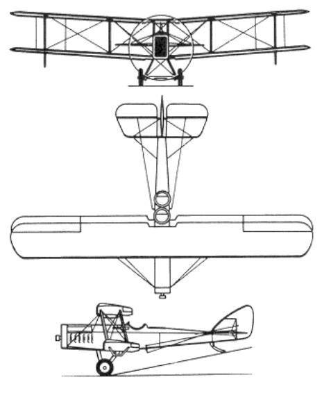
Standard armament of the I-5 was two synchronised 7.62mm PV-1 machine-guns and up to 40kg of bombs could be carried on underwing racks. The circular-section fuselage had a metal tubular framework with metal sheet covering forward and fabric aft. The wooden wings were fabric covered. The axle-type undercarriage could be fitted with wheel spats.
A number of I-5s were still in use at the time of the German invasion of the Soviet Union in June 1941, when a few were pressed into service by Black Sea naval airmen for ground attack. Interestingly, I-5s had previously been used in Soviet Zveno ‘parasite’ experiments, being launched in the air from the TB-3 mother ship.
Engine: 1 x M-22, 355kW Max take-off weight: 1355 kg / 2987 lb Empty weight: 943 kg / 2079 lb Wingspan: 10.2/7.4 m / 33 ft 6 in / 24 ft 3 in Length: 6.8 m / 22 ft 4 in Wing area: 21.3 sq.m / 229.27 sq ft Max. speed: 278 km/h / 173 mph Cruise speed: 250 km/h / 155 mph Ceiling: 7300 m / 23950 ft Range w/max.fuel: 660 km / 410 miles Armament: 2 x 7.62mm machine-guns Crew: 1
Airco DH-4 production in Russia at the Dux factory was about to start in October 1917, but manufacturing was frozen due to the absence of the engines, though preparations did not stop. N.N.Polikarpov was steadily working on blueprints for the assembly lines. During the Civil War some of the latest DH-9 and DH-9A were captured, and modifications were included into the project.
When the Bolshevik government decided to gain airpower, one of the simplest solutions was to restart old projects. Intermediately DH-4, DH-9/R-1, DH-9/R-2 were built (1921-1923), using parts imported from the Great Britain. Production of the M-5/Liberty engine allowed the first Soviet mass production aircraft. First combat ready R-1 were built on the GAZ-1 factory under the supervision of N.N.Polikarpov in 1923. They were named “Imeni Izvestij VTsIK” and “Moskowskij Bolshevik”. Mass production started same year at GAZ-10 (Taganrog).
The first squad of 19 aircraft was designated ‘Lenin’ and presented to XIII Congress of the RKP(b) on May 23-31 1924.
It is not correct to call the R-1 a copy of DH-4/9. It was built from all domestic materials, whole construction was revised to utilize technologies available in war burnt Russia. It was heavier, carried more payload and had a substantially strengthened construction.
Group of R-1s performed a Moscow-Peking-Tokyo flight (M.M.Gromov as a leader), proving high quality and reliability of the first Soviet series aircraft.
The R-1 became the first Russian aircraft to be exported – Afghanistan purchased some 20 in 1923-1924.
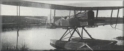
One hundred and twenty-four of the MR-1 floatplane version of the R-1 with wooden floats were built.
All-metal floats for the R-1 were designed by engineer Munzel. The float skin was corrugated aluminum and the underside smooth aluminum. The floats were attached to system of struts (14 tube elements). The steel tubes had an aerodynamic cross-section.
As the PM-2 floatplane ( Polikarpov and Munzel) / MR-2 trials were performed during Fall 1927 by pilot Ya.N.Moiseev, timing by V.V.Nikitin. Performance was better than one of the MR-1 on wooden floats due to substantial weight savings.
PM-2
Only one was built and no production followed due to shortage of aluminum and light alloys.
The R-2 biplane reconnaissance aircraft was based on the R-1.
During 1924-1931 approximately 2800 were produced.
Engine: 1 x M-5, 295kW Max take-off weight: 2200 kg / 4850 lb Empty weight: 1450 kg / 3197 lb Wingspan: 14.0 m / 46 ft 11 in Length: 9.2 m / 30 ft 2 in Height: 3.3 m / 11 ft 10 in Max. speed: 200 km/h / 124 mph Cruise speed: 185 km/h / 115 mph Ceiling: 5000 m / 16400 ft Range w/max.fuel: 700 km / 435 miles Armament: 2 machine-guns, 200kg of bombs Crew: 2
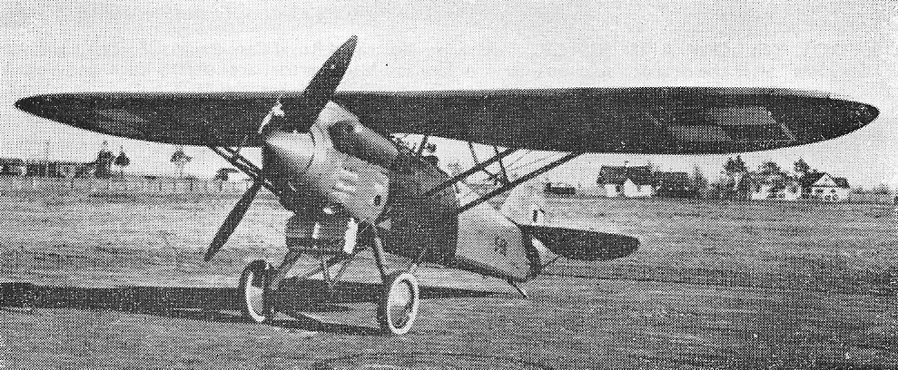
The history of the first Soviet fighters begins with the decision to create a construction bureau at GAZ No.1 in Moscow (formerly known as Duks and created by Yulius Alexandrovich Meller in 1893) in January 1923. Initially the leadership of this bureau it was assigned to N. N. Polikarpov, but as early as February D. P. Grigorovich, who had recently returned to Moscow, was appointed to this post.
At the end of 1923 Grigorovich would organize his own construction group made up of renowned specialists such as AN Sidielnikov, VL Korvin-Kerber, AA Krylov, VV Kalinin and VL Moisienko and an experimental construction workshop. His main task was to achieve an improved development of the I-1 fighter capable of showing more satisfactory performance.
The projection of the new fighter, called Grigorovich I-2 (Russian: Григорович И-2), began on January 1, 1924. It is noteworthy that until 1926 this model was known indistinctly as I-2 or I-7. The denomination I-7 would finally disappear to leave only that of I-2, with which it is found in the documentation of the period.
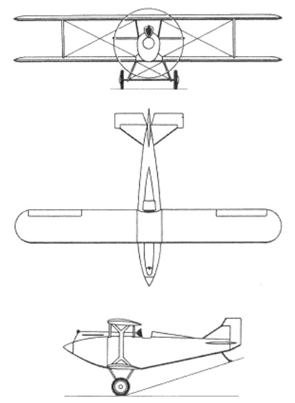
Grigorovich’s new fighter was designed as a single-engine, single-seat biplane of conventional configuration, built of wood and fabric. It basically repeated the construction and power plant of the previous I-1, but incorporated a new fuselage, modified interplane pillars and changes in the shape of the hood to improve visibility.
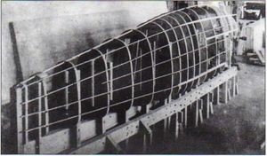
The fuselage had an oval section and in the bow section it had a metal structure to which the power plant was fixed. Starting from the pilot’s cabin, the fuselage became a wooden construction with a monocoque structure and sheet metal covering, glued around the structure.
Grigorovich I-2 fuselage construction
The biplane wingbox featured wings of equal span, without offset. The upper plane was fixed by means of an N-type structure built with steel tubes and the planes had I-shaped supports made of duralumin and fully faired. Wing stiffness ended up being achieved by simple tension cables.
The wing was built of wood and featured a double spar structure. The ailerons were located only on the lower wing, protruding slightly outside the trailing edge. The wing skin was made of plywood. The trailing edge was made with steel cables and in the plan view it was shown as the wave trace.
Both the tail and the wings were built on an aluminum frame covered in fabric.
The landing gear had a pyramidal structure quite characteristic for the time. The supports were made of steel tubes and the amortization was achieved by means of 16 mm diameter rubber tensioners. For winter operations the train of wheels could be replaced by another with skis.
The I-2 used the M-5 engine with 12 cylinders in V and 420 hp of power (copy under license of the North American Liberty L-12 engine).
In front of the cockpit, in the central section of the fuselage, the main fuel tank with a capacity of 200 liters was located. Another 96-liter fuel tank was located in the center plane, in the center of which was a fuel-in-tank sensor using a float.
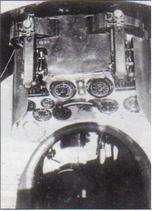
The I-2’s armament comprised two 7.62mm Vickers or PV-1 machine guns with 500 rounds each. On most I-2s the machine guns protruded from the fuselage.
Top view of the I-2 cockpit, showing the location of the instrument panel and the two machine guns.
The construction of the I-2 began on February 1, 1924 and the subsequent events are not very clear if we discount the scandal of late 1924 and early 1925, when during the tests of the I-2 and IL-400 the subject came up about its authorship. It was about the attempt of the GAZ No.1 specialists to “collectivize” these creations, eliminating not only the authorship and creative work of their designers, but also the responsibility for development. Polikarpov and the group of specialists, who worked on the IL-400, ended up giving in and authorized the transfer of all the rights to their creation to GAZ No.1, but Grigorovich was intransigent and the matter went to court.
During the hearing, the constructor declared: “The I-1 and I-2 aircraft, from their primary conception to the smallest details, have been developed by me with the participation of my close collaborators, the engineers AN Sidielnikov and VL Korvin-Kerber, with the support of drawers Shvarts, Nikitin and others on a smaller scale. The engineer VV Kalinin developed the diagrams for the fuel pump and the pipes, but they were not used in the end. Engineer AA Krylov worked out the control system from my sketches.”
Grigorovich’s opponents, the engineers Sutugin, Uspasski and Shirokov told Grigorovich that during the development process he had left for Leningrad, that using his position as director of the GAZ No.1 he pushed aside a group of specialists, who his direction in the projection and construction of airplanes was superficial and in terms of the originality of his designs the new fighters lacked it as they were very conventional schemes.
Despite this, the director did not give in and, determined not to give up his leadership, continued the discussion showing the first sketches, calculations and drafts of the I-1 and I-2 fighters. Finally, taking into account his authority and experiences, but above all his stubbornness, it was decided to keep Grigorovich alone as the author of these designs.
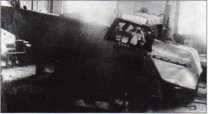
Breakage of one of the supports during the final stage of assembly of the prototype I-2 on August 19, 1924.
Construction of the I-2 was proceeding smoothly, and the prototype was found ready by September 6, 1924. After the review by a committee of the Scientific Committee of the VVS Directorate (UVVS) and several ground tests of the engine’s work, it was decided to allow flight tests. On November 4, pilot AI Zhukov took the aircraft into the air for the first time.
The results of the first flight were considered satisfactory. Zhukov noted the ease of control, the short take-off run, and the ease of landing.
Subsequent flights, aimed at establishing the maximum speed and the flight ceiling, resulted in the need to make some adjustments to the control surfaces, the controls and the power plant. Contrary to expectations, Alexandr Zhukov noted that control of the plane had worsened. In low-speed flight it was not very stable and when accelerating it tended to dive. After the sixth flight Zhukov decided not to continue the flights. The cause would soon be found: the tail skid in his operation pressed the flight controls.
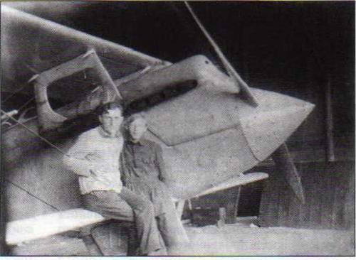
On November 19, 1924, the I-2 was flown by MM Gromov and VN Fillipov, who found nothing strange in the behavior of the aircraft, but criticized the cabin for being cramped and uncomfortable. Zhukov was a small and thin man, so this problem could not be appreciated.
According to Filippov: “- The cabin in the prototype I-2 was calculated for a gnome, or in any case not for a normal man. You can sit on it only from the side because the instrument panel is very close… Despite the good flight characteristics this plane can only be seen as a competition plane.”
Opinions about the plane were different not only among the pilots. To clarify the truth, a commission was called, which defined that criticism of the I-2 was harmful and threatened the delivery times. The commission itself inadvertently contributed to this, since the report of its work was delivered only on February 3, 1925.
The I-2 prototype during the final stage of assembly in September 1924.
The tests at the Scientific Experimental Aerodrome (NOA according to the acronym of Nauchno Opytni Aerodrom) began only from March, but already from the first flight new problems with the plane began to appear.
It was pointed out that the model was dangerous from the point of view of the possibility of fire because gasoline was leaking from the hose that started from the upper fuel tank. This was an issue easily resolved by any mechanic, but for inexplicable reasons and due to bureaucratic rules it became necessary to sign and approve a pile of papers before solving the problem.
The NOA tests showed some longitudinal instability, so it was proposed to increase the empennage surface. In April the new queue was built and installed. These were the last flights in Moscow of the prototype I-2.
All subsequent work on the I-2 would be developed in Leningrad. Some sources detail that the cause of the abandonment of Moscow was due to disagreements between Grigorovich and the director of GAZ No.1 Niemtsov. In any case, by the beginning of 1925 the Aviotrust management had decided to create a naval aviation construction department in Leningrad and there was no better candidate than Grigorovich to lead it.
Grigorovich and his group received Factory No.3 “Krasni Liotchik” (later Factory No.23) as a production base. Although it was expected that the main task of this Factory would be the production of seaplanes, the improvement works on the I-2 fighter were moved to this new location together with its author. For this reason, on April 30, 1925, the fighter was disarmed and transferred by rail to its new destination.
Flight tests in Leningrad were carried out between May 25 and June 25, 1925 with pilots AD Mielnitsky and LI Giks at the controls.
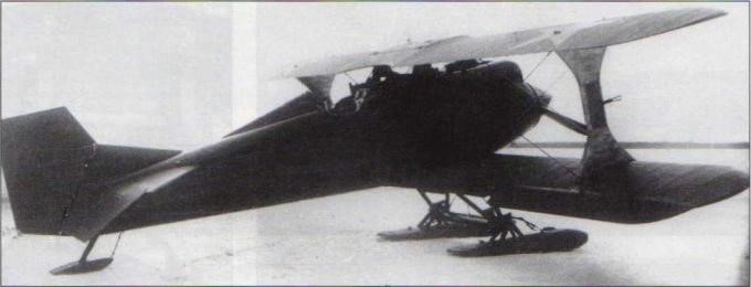
Grigorovich I-2 with ski undercarriage.
Once again ideas and desires arose to improve flight control, increase the wing area, enlarge the cabin and even install a turbocharger.
By that time preparation for series production at the GAZ No.1 and GAZ No.3 factories finally began, so Grigorovich had no intention of risking changes. The I-2 entered production with a whole collection of problems and limitations and still very far from being able to satisfy the requirements of the VVS.
Even without concluding the tests, at the end of April 1925, the Technical Scientific Committee of the VVS issued a request to produce a small experimental series of 10 copies I-2, despite not reaching the maximum speed nor some important features. The production of the Polikarpov IL-400 fighter, which had now been renamed I-1 in VVS documents, was also being prepared. The first pre – series copies of both manufacturers began to fly at the beginning of 1926, but by March of that year the NOA specialists expressed their dissatisfaction in relation to the Polikarpov model. This conclusion was reinforced by the doubts caused by the use of a wooden cantilever wing in a fighter and the control problems associated with piloting techniques, an opinion that would be reinforced after the destruction of two I-1 specimens during the tests, both product of the flat spin entry.
Fighter I-2 No.1911 after a forced landing of the young pilot Sukhanov near the village of Zagvozdka on February 22, 1930.
In this way, Grigorovich ‘s model remained as the only competitor to the VVS hunting post. The military, despite approving the introduction of the model, kept demanding the improvement of the plane. This would be tried in a new version that saw the light with the denomination I-2bis.
Serial production began in 1926 and continued until 1928. During this period the GAZ No.3 factory delivered 62 examples of the model not counting the prototype, which had been created at GAZ No.1 in Moscow.
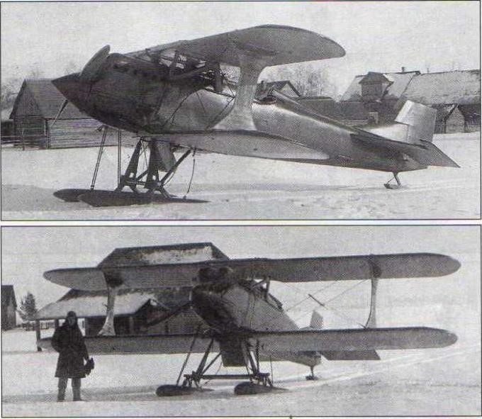
Grigorovich I-2 fighter with ski undercarriage during delivery tests.
The I-2 was the first Soviet-built fighter to enter service with the VVS. For its time it was a fairly complex fighter. Unfortunately, the model was over-heavy. The lack of standards in the industry caused the examples to differ from each other, which created great differences in performance from one aircraft to another. The cabin was cramped, the pedals were poorly arranged, the weapons were inconvenient to use, the visibility from the cabin was not good. Nor was it possible to definitively solve the problem of engine overheating, carried over from the I-1 model. To improve cooling in some examples, two Lamblin radiators were installed between the landing gear. This version of the plane received the name I-2 prim and was characterized by improving the cooling issue, affecting performance.
Despite the fact that the VVS, in the absence of better options, approved the introduction of the I-2 model in service, the military kept demanding the improvement of the aircraft. These improvements would come in a new version that came to light with the I-2bis.
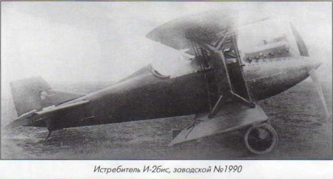
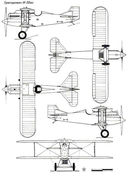
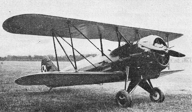
The Grigorovich I-2bis (Russian: Григорович И-2бис) was a version of the I-2 in which some structural reinforcements were introduced and the technological process was improved in order to facilitate production. The cockpit was enlarged and the distribution of instrumentation and equipment was improved. From the external point of view, the new interwing struts, modifications to the landing gear, tail unit and improved hood shape were easily noticeable.
I-2bis number 1990, the first prototype obtained as a development of a production I-2 in 1927
Grigorovich’s I-2bis fighter incorporated few visible changes. Perhaps the most noticeable were the coatings on the interalar supports. In general, it was a single-engine, single-seat biplane of conventional configuration, built of wood and fabric.
The fuselage had an oval section and in the bow section it had a metal structure to which the power plant was attached. Starting from the pilot’s cabin, the fuselage became a wooden construction with a monocoque structure and sheet metal covering, glued around the structure.
The biplane wingbox featured wings of equal span, without offset. The upper plane was fixed by means of an N-type structure built with steel tubes and the planes had X-shaped supports made of duralumin. Unlike the I-2 this structure lacked the fairings on the ends. Wing stiffness ended up being achieved by paired tension cables. Other differences from the original I-2.
The wing was built of wood and featured a double spar structure. The ailerons were located only on the lower wing, protruding slightly outside the trailing edge. The wing skin was made with plywood up to the location of the first spar. From there tissue was used. The trailing edge was made with steel cables and in the plan view it was shown as the wave trace.
Both the tail and the wings were built on an aluminum frame covered in fabric.
The landing gear had a pyramidal structure quite characteristic for the time. The supports were made of steel tubes and the amortization was achieved by means of 16 mm diameter rubber tensioners.
The I-2bis kept the M-5 engine with V-cylinders and 400 hp (licensed copy of the North American Liberty L-12 engine). It stood out for the careful work on the engine hood, of which at least two types were used. The most remarkable symbol of the upper region of the hood was the pipe through which the air flow entered the two “Zenit” carburettors. Cooling was basically achieved by means of a Lamblin radiator that could vary its angle of incidence by around 70º. The control of this radiator was carried out from the cockpit. A number of I-2s were delivered with fixed radiators attached to the fuselage.
In front of the cockpit, in the central section of the fuselage, the main fuel tank with a capacity of 200 liters was located. Another 96-liter fuel tank was located in the center plane, in the center of which was a fuel-in-tank sensor using a float.
The I-2bis’s armament comprised two 7.62mm Vickers or PV-1 machine guns with 500 rounds each. In most of these examples the machine guns were inserted somewhat deeper in the fuselage.
Grigorovich I-2bis
The first I-2bis was obtained as a modification of a production I-2 appearing in the spring of 1927. Even without finishing their flight tests, the VVS requested a series of 140 copies, which would soon be reduced to only 50. Despite the fact that there are documents that establish the delivery by GAZ No.1 of Moscow of 7 I-2bis fighters in 1927, subsequent investigations by M. Maslov confirm that this could not happen. It is not ruled out that it could be some copies with a certain level of modifications, delivered under the name I-2bis, but clearly it is not the same model that later coined this name.
According to IM Kostkin, one of the creators of the Polikarpov IL-400 and later in charge of the serial introduction of Grigorovich’s fighter at Moscow’s GAZ No.1, the first “real” I-2bis was ready only in the summer of 1928. Preparation for serial production at this factory was plagued with problems due to difficulties with the shipment of technical documentation from Leningrad. For this reason, many of the construction elements were redesigned, which resulted in a decrease in the flight characteristics of these specimens. This caused pilots to rate the I-2bis as an inferior model to the I-2.
In the minutes of the conclusion of the tests of the I-2bis fighter, signed by the head of the NII VVS Gorshkov, it was highlighted: “The I-2bis aircraft with its low speed, climb and ceiling, as well as poor manoeuvrability cannot be considered a modern fighter. Compared to the I-2 it is inferior due to its performance, but the constructive and operational changes make it a better plane. After the elimination of the problems indicated in I-2bis it could be used as a transition training aircraft.”
It was clear that the VVS were in a difficult situation. Polikarpov’s I-3 fighter was just beginning to be built, there were no other domestic candidates, and buying modern fighters abroad was too complicated at the time. Precisely for these reasons in the meeting with the head of the VVS PI Baranov, held in the fall of 1927, it was decided to build the I-2bis knowing that it did not fully meet the requested requirements.
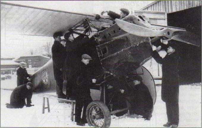
Students study the details of an I-2bis fighter in the winter of 1930.
The Moscow GAZ No.1 would build 50 copies I-2bis. Starting in 1927 and as part of a further restructuring of the aircraft industry, GAZ No.1 was renamed Factory No.1 Aviajim.
GAZ Factory No.3 (from 1927 Factory No.23) in Leningrad would produce between 1928 and 1929 28 examples of the modified fighter, bringing the total number of aircraft produced between I-2 and I-2bis to 140 copies.
Although production of the I-2 and I-2bis officially ended in 1929, isolated examples were delivered some time later. The last of these was the I-2bis with serial number 1990, delivered in May 1931 to the Borisoglebsk Flight School (actually it was the first I-2bis built modified in 1927 on the basis of an I-2 of series For three years it had been abandoned in the factory before its delivery was defined.
I-2bis used as a trainer at the Borisoglebsk Flying School in 1931.
The 50 I-2bis produced in Moscow were delivered to units in Gatchina (Trotsk), Bryansk and Vitebsk. Some examples from the beginning were delivered to flight schools, so by 1929 they were used at the Borisoglebsk Flying School.
I-2bis fighter of an operational unit in the early 1930s.
The first two I-2bis arrived in the summer of 1928 at the Bryansk 15th Aviation Brigade and by the end of the year their number had risen to a dozen. At the beginning of 1929 from the experiences of exploitation in Bryansk a report was written in which the I-2bis was evaluated as heavy and inert at the controls. It was noted that the dive was stable, but it was difficult to get out of it.
This damaged I-2bis fighter is the number 5 unit operated by the Leningrad military district in the early 1930s. As a distinctive feature, the symbol of the Order of the Red Banner painted on the sides can be seen.
From the end of 1928 the I-2bis produced by the GAZ No.23 of Leningrad began to arrive at the units. These specimens were characterized by a better finish and superior performance.
According to a report by the engineer PM Kreison issued in the summer of 1928, at that time 62 examples of the I-2 and I-2bis versions were in service. Most of them were located in the Leningrad military region and the Baltic aviation.
The report highlights: 6 I-2s in the 1 Gatchina Squadron; 10 I-2 in Krichevitsi’s 11 Squadron; 4 I-2s in the Caucasus Special Army, in Baku; 7 I-2 in the Vitebsk 7 Squadron; 7 I-2s at the Orenburg Air Combat School; Some unspecified amount at 44 Bryansk Air Park; An unspecified number in the 17th Squadron of the 15th Aviation Brigade.
In 1928, following an agreement with the Persian government, it was decided to sell to this country a certain number of R-1 reconnaissance planes, U-1 trainers and I-2bis fighters. These copies were built under a “special task”. At least 8 examples were built in this batch, bearing serial numbers 2116, 2117, 2118, 2119, 2120, 2121, 2122, 2123. These I-2bis were armed with Vickers machine guns and featured increased radiators to enable warmer weather operations. The fighters were packed in boxes for shipment by sea and the spare parts in other smaller boxes. No evidence has been found to show that this export took place.
It should be noted that between 1925 and 1926 Grigorovich worked on the projects for improved versions of the I-2 fighter. The first version, sometimes known as the Grigorovich I-3, kept the Liberty engine, but had to reach 270 km/h. A later version incorporated a Wright Tornado 3 engine. Named I-4, it was to reach a maximum speed of 300 – 350 km/h with a flying weight of 2,000 kg. These projects never got past the stage of conceptual ideas.
Artist’s conception of an I-2 fighter of a Leningrad Order of the Red Banner unit in flight.
Versions:
I-2 – Original version of the fighter developed on the I-1 model. First flight on November 4, 1924. 62 examples were built in the Leningrad GAZ No.3 between 1926 and 1928.
I-2bis – Improved version with structural reinforcements, wider cabin, new inter-wing mounts, changes to the landing gear, tail unit and new drive cowling. It was produced at factories No.1 in Moscow (50 copies) and No.3 in Leningrad (28 copies).
I-2prim – A number of modified aircraft with two Lamblin radiators between the landers. This version was characterized by improving the issue of cooling, affecting performance.
Grigorovich I-2.
Type: I-2 Powerplant: 1 x 400 hp M-5 V-12 Wingspan: 10.80 m Wing area: 23.46 m² Length: 7.32 m Height: 3.00 m Empty weight: 1130 kg Loaded weight: 1530 kg Fuel + lubricant capacity: 236+35 kg Maximum load capacity: 400 kg Wing loading: 57.5 kg/ m² Power load: 3.8 kg/hp Speed at sea level: 240km/h Maximum speed at 1000 m: 239 km/h Maximum speed at 4000 m: 230 km/h Landing speed: 95 km/h Range: 650 km Endurance: 2.5 h Service ceiling: 5740 m Rate of climb: 420 m/min Turn time: 13s Time to 1000m: 2.1 min Time to 2000m: 4.6 min Time to 3000m: 8.2 min Time to 4000m: 13 min Time to 5000m: 21 min Landing run: 190m Take-off run: 120m Armament: 2 x 7.62mm PV-1 machine guns Accommodation: 1
I-2bis Powerplant: M-5 400 hp Wingspan: 10.80m Wing area: 23.46 m² Length: 7.32m Height: 3.00m Empty weight: 1,152 kg Loaded weight: 1,575 kg Wing loading: 66.92 kg/m² Power Load: 3.8kg/hp Top speed: 235km/h Cruising speed: 190km/h Landing speed: 95km/h Rate of climb: 420m/min Range: 600km Endurance: 2.5 hours Turn time: 16 sec Service ceiling: 5340 m Time to 1000m: 2.4min Time to 2000m: 5.5min Time to 3000m: 9.6min Time to 4000m: 15min Time to 5000m: 25min Landing run: 210 m Take-off run: 160m Armament: two 7.62mm PV-1 synchronized machine guns Accommodation: 1
In April 1935, the Polish government, looking for an intermediate military trainer, bought two Avro 621 Tutor trainer aircraft. Production was ordered in the PWS (Podlaska Wytwórnia Samolotów – Podlasie Aircraft Factory). Negotiations began for licensed production in Poland but reached an impasse. Under the contract, the Polish Avro 621 were equipped with Bristol engines, and the engine production in Poland has not yet been established. When the license was obtained, there is a problem with the release of the licensed copies of the aircraft. As a result, both Avro 621 were sent to Podlaska Wytworna Samolotow (PWS) to review the design.
In 1935, Antoni Uszacki of the PWS modified the design, fitting it with a Wright Whirlwind engine, produced under licence in Poland. The new engine cowling was much longer than the previous Townend ring type, with a carburetor air intake below it. The wing construction was changed from metal to wooden, better fitted to PWS capabilities, and the rectangular wing tips were rounded. Also some other details were changed, such as a tailskid instead of a tailwheel.
A series of 40 aircraft was built in 1935-1936. They were assigned military numbers 80-1 to 80-40. Designated PWS 18, these machines differed only “cosmetic” improvements and American Wright J-5B “Cyclone” engines.
They were not produced in larger numbers because a successful indigenous Polish advanced trainer, the PWS-26, using the same engine, was designed and entered production.
PWS-18s were used in the Polish military aviation flight schools and training squadrons of the 4th Regiment in Torun, among others in Airforce Training Center in Dęblin, an NCO school for minors in Bydgoszcz and in training escadres of air regiments. None survived World War II.
Most of the aircraft survived until the outbreak of war, and for some time they have been used to provide communications between the Polish armies. Some PWS 18 were then captured by the Germans and used in flight schools Luftwaffe in Poland.
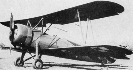
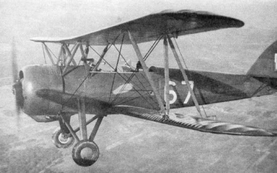
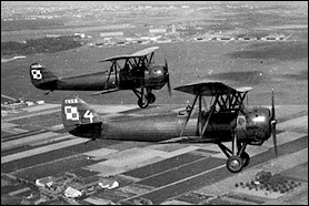
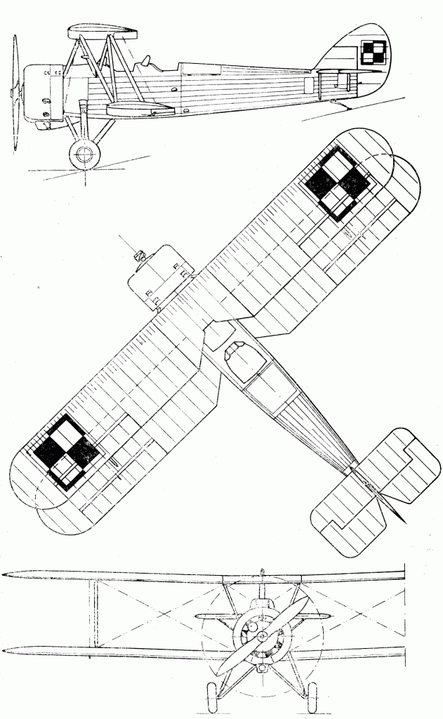
The PWS-10 was the first Polish-designed fighter intended for military service as a replacement for the numerous foreign designed, Polish constructed aircraft then operated.
A single-seat fighter, the PWS-10 was first flown in 1928. Sixty-five were delivered to the Polish Air Force.
The parasol-winged inline-engined PWS-10, the first Polish fighter to enter series production, served in the Spanish Civil War.
Engine: 450 hp Skoda-Lorraine 12 cyl W Span: 36 ft 0 in Length: 24 ft 7.5 in Height: 8 ft 6 in MAUW: 3290 lb Max speed: 152 mph Time to 16,300ft: 15 min 15 sec Service ceiling: 21,300 ft
In 1943 the Piper Aircraft Company undertook to design and build for the United States Army Air Force (USAAF) an aircraft ambulance.
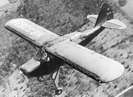
After studying the specification it was decided to base the design on an existing model, the Piper J-5C, the first prototype was built using an existing Piper J-5CO (O for Observation), this first aircraft being given the serial number (SN) 5-1387 and the registration: NX41552.
The most noticeable change being the reconstructed upper fuselage, a large dorsal addition to cater for stretchers. Otherwise the aircraft was unchanged, including the engine which remained as in the Piper J-5C, the Lycoming O-235 producing 100 hp.
Piper YL-14 NX33534
First flight was on the 16th June 1943 and after satisfactory flight trials from October of that year and into 1944 major modifications were made including larger windscreen and glazed areas, long landing gear shock absorbers, increased fin height and size, and a first for Piper, full span slots on the wing leading edges, generous flaps were also incorporated, another first. This aircraft was now designated the Piper J-5D.
In 1944 a second prototype was converted from another J-5C, registration NX33529, now designated as a Piper L-4X, in line with the military series of ‘L’, with the SN 5-3001, the first flight being on the 9th September 1944. All the changes were incorporated into this aircraft along with a larger engine, Lycoming O-290-A giving increased power.
The Approved Type Certificate for the new Model: Piper L-14 was issued 31st July 1945 (ATC 760) to the Piper Aircraft Company, Lock Haven, Pennsylvania.
The definitive and complete Piper L-14 incorporating all the changes including large glazed area, turtle deck, slots and flaps, and undercarriage shock absorbers was SN 5-3002, registered NX-33534 which flew on the 29th February 1945.
The production of five examples was completed for service evaluation, these aircraft were designated YL-14 with the serial numbers from 5-3001 to 5-3005.
The two original prototypes were modified to the same standard as the production examples, YL-14, and the service trails commenced in May 1945, the newly built Piper YL-14 were delivered in June of the same year, these last with the recessed slots, flaps and glazed, removable turtle deck which permitted a stretcher to be loaded, similar to the Naval models designated HE-1/AE-1.
The USAAF issued an order to build 850 examples of the Piper L-14 Army Cruiser.
Piper YL-14 NX33534
Howard Piper was the engineer for this project, Dave Long the chief of design and Tom Piper the chief flight test pilot with Clyde Smith Senior, the pilot involved with the test flying and evaluation during the whole production run. It was found necessary to increase the wingspan by three feet outboard of the leading edge slots to improve flight handling.
The construction and dimensions for the L-14, now named ‘Army Cruiser’ was very similar to the Cub Cruiser or Super Cruiser, except for the larger engine and the changed interior to accommodate the stretcher. Alloy steel tube fuselage, aluminium alloy spars with aluminium ribs, fabric covered, wing struts, bracing wires for the tail surfaces, all standard for the pre-War Piper models.
The one big difference of this model was that this was the first model to incorporate flaps, up to 40% being available which when used with some power from the engine resulted in an airspeed of less than 20 Knots, these combined with the slots gave full control which was demonstrated on the first flight.
At the express wish of the USAAF, the capability to operate safely from rough and unprepared fields large balloon tyres were tested, (size 600 X 6) and a robust skid made by R.C.A. Scott.
The electrical system was the normal military specification: 28 Volts along with a voltage regulator using an engine driven generator, and a powerful starter motor.
In the cockpit the panel instruments were provided with lighting for night flying, a landing light was positioned on the left wing powered by a 24-volt battery. Two pilots in front, dual controls, and an observer’s seat in the rear that swivelled for viewing out the back or for writing at a built-in desk.
A full flying panel was installed, including, left to right: clock, air speed indicator, turn and slip, vertical speed indicator, compass, altimeter, engine rpm gauge, oil temperature and pressure, ammeter.
The engine fitted was a Lycoming O-290-1 (O-290-C) producing 130 hp at 2,600 rpm and a wooden Sensenich propeller, 76JB44, allowing for a maximum speed of 115 mph (190 km). Maximum take off weight of 1,800 lbs (820 kg).
This definitive model of the Piper L-14 Army Cruiser never went into production as in August 1945, right at the end of the Second World War, the USAAF ceased to have an interest in this model or a need for it.
The five initial aircraft, YL-14, and the other nine L-14 comprised the total production run for this aircraft, in all only fourteen were completed.
At the end of the War the USAAF authorised the Piper Aircraft Company to sell these aircraft into the civilian market.
The 14 aircraft produced:
Piper YL-14 5-3001 last reported in the Philippines: 22 July 1945 5-3002 last reported in Japan: 3 May 1948 5-3003 sold to the Philippines as P1-C159, never officially registered. 5-3004 sold within the USA as NC-66526, never officially registered. 5-3005 sold within the USA NC-69225, reregistered as N14YL, still airworthy.
Piper L-14 Army Cruiser 5-3006 sold within the USA NC-41399, reregistered as CU-P19. No records since 1946. 5-3007 sold within the USA NC-41594, exported to Cuba, CU-P18, CU-N18 then to Spain as EC-AAP. Now airworthy, May 2003. 5-3008 sold within the USA NC-41598, exported to Venezuela, no records since 1946. 5-3009 sold within the USA NX-41352, sold to Mexico XB-COP, no records since 1946. 5-3010 sold within the USA NC-41593, to Mexico as XB-CAQ, no records since 1946. 5-3011 sold within the USA NC-41595, to Uruguay as CX-AFX destroyed in a fire. 5-3012 sold within the USA NC-41596, to Argentina LV-NCM not officially registered.
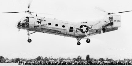
Developed from the US Navy’s HRP-2 Rescuer, the Piasecki PD-22 tandem-rotor helicopter prototype (US Air Force designation XH-21) was first flown on 11 April 1952 with Len LaVassar and Marty Johnson at the controls.
Winner of a USAF competition for an arctic transport helicopter, the new craft looked almost like the HRP-2, but weighed 6630kg fully loaded, more than twice the earlier machine. A 1425hp Wright R-1820 engine (derated in early models to 1150hp) and a 0.9m increase in rotor diameter to 13.4m gave it much better performance than the HRP-2. The H-21 used the single engine with tandem three-blade rotors. Structurally, it was a new aircraft. (TC 1H12, 1H16, H1AL, H3EA, H8WE, H9EA, HR35).
The Work Horse could carry fourteen fully equipped troops or an equivalent weight of cargo. Features included a rescue hoist and inflatable donut-shaped floats around its wheels for landings even on marshy tundra. Winterized to support Distant Early Warning (DEW) Line radar stations far to the north, extensive cold-weather testing was performed atop Mount Washington, the highest peak in New Hampshire’s White Mountains, as well as in the climate hangar at Eglin Air Force Base.
Eighteen Model PD-22 / YH-21 helicopters had been ordered in 1949 for USAF evaluation, these being followed by an initial production batch of 32 H-21A helicopters, named Workhorse in USAF service. For use by the Military Air Transport Service Air Rescue Service, the H-21As were each powered by a derated 932kW Wright R-1820-103 engine; the first flew in October 1953. Six more were built to USAF contract but supplied to Canada under the Military Assistance Program. Vertol produced in 1957 a small number of Vertol Model 42A, exclusively Canadian civil conversion of RCAF H-21B helicopters used to supply stations of the mid-Canada radar chain.
The second production variant was the H-21B, which used the full power of the 1063kW R-1820-103 to cover an increase in maximum take-off weight from 5216kg to 6804kg. The Air Force eventually purchased 163, mainly for Troop Carrier Command, and these had autopilots, could carry external auxiliary fuel tanks, and were provided with some protective armour. They could carry 20 troops in the assault role.
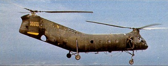
The Army became aware of the H-21’s potential as a medium utility helicopter soon after the type’s maiden flight, and in 1952 awarded Piasecki a contract for the production of the H-21C variant. This aircraft retained the H-21B’s extensive armor plating and ability to carry two external fuel tanks, but had such additional features as increased troop capacity and a 4000-pound capacity belly sling hook. The Army procured 334 H-21C Shawnees, with deliveries beginning in August 1954. In addition, the Army obtained at least sixteen H-21B aircraft from the USAF; the majority of these machines were ultimately brought up to H-21C standard, and all were known as Shawnees despite their origins as Work Horses. The B and C variants of the H-21 were used in Vietnam, equipped with 12.7 or 7.62mm light machine guns which were fired through the cabin doors.
While the Navy’s helicopters had a 600hp Pratt & Whitney R-1340 engine, those for the Army had a Wright R-1820. Thirty-three of the H-21A were assigned to SAR units in the Arctic and another five were sent to Canada. Foreign operators of the H-21 included the German Army (26), French Army (98), French Navy (10), Japanese armed forces (10) and Swedish Navy (11).
The US Army’s equivalent was the H-21C Shawnee, of which 334 were built. This total included 98 for the French army, 10 for the French navy and six for Canada; 32 Shawnees were supplied to West Germany, serving with the army’s Heeresfliegerbataillon 300. The first deliveries to the Army were in September 1954 with production continuing until March 1959. The H-21C, redesignated CH-21C in July 1962, had an underfuselage sling hook for loads of up to 1814kg. Production deliveries were made between September 1954 and March 1959, later helicopters acquiring the company designation Model 43 when the Piasecki Helicopter Corporation became the Vertol Aircraft Corporation in 1956. The H-21 A and H-21B retrospectively became the Model 42. In 1962 the H-21B and H-21C were redesignated as, respectively, the CH-21B and CH-21C.
Two turboshaft conversions of H-21C airframes were the Model 71 (H-21D), with two General Electric T58 engines first flown in September 1957, and the Model 105 which had two Avco Lycoming T53s in 1958. The variant was not adopted for production. From the latter was designed the Vertol 107 (Boeing Vertol H-46 series).
Most Shawnees were withdrawn from the active inventory by 1965.
H-21C
It set a closed-course distance record of 1,199 miles in Aug 1957 with extra fuel tank. It was a Shawnee dubbed ‘Amblin’ Annie that made the first non-stop helicopter flight from one coast of the United States to the other, being refuelled in flight from a U-1A Otter in Aug 1957. More significantly, the H-21 was the first American military helicopter type to be deployed in appreciable numbers to South Vietnam: the first four Shawnee units arrived in that country between December 1961 and September 1962. The H-21 also gained the dubious distinction of being the aircraft in which America’s first Vietnam casualties were killed; four Army aviators died in July 1962 when their Shawnee was shot down near the Laotian-Vietnamese border.
“I was working as a helicopter mechanic with the U.S. Army Aviation Service Test Board in 1954 and 1955 and we received some of the first production H-21Cs for operational testing; I was assigned to serial number 51-15888, tail number 115888, the eighth built, and I recall us having 115881 also which I believe was the one we picked up at Edwards AFB in 1955. The Air Force did all engineering flight testing for the Army and when they completed tests on the H-21C version (in preparation for their USAF H-21B version ordered after the “C”), a small group of us from the Fort Rucker Test Board went to Edwards to take over the ship and perform some high altitude and desert tests before flying back to Rucker. Arriving at Edwards, complete with papers and “secret” clearances, we promptly discovered that the USAF’s Army H-21C was in terrible condition and unairworthy. Much to their dislike and consternation, we hung around the air base for several days while we performed an inspection and changed the Wright 1820 engine – the desert flying had eaten up the cylinders and bearings to the point that the 19-gallon oil tank wouldn’t sustain a single flight! Needless to say, there was some exciting experimental jet activity going on at Edwards at that time and we GIs were in no hurry to leave as we had a front line seat on the test ramp. We spent a few weeks at an Apple Valley dude ranch, parking the helicopter in the desert, and refueling at George AFB. Each day we flew several sorties into the White Bear region and did a few exciting running takeoffs at White Bear Lake. We made an uneventful (mostly), but rather warm and humid, flight back to Rucker, taking a pretty straight course from San Antonio across Texas, Louisiana, Mississippi and into Alabama. A late evening thunderstorm threw us off course during a night flight leg and we made an “off-airport” landing in a drenched high school football stadium in Mississippi (still lit up following a game); the locals fed us and I wound up spending the night RON in a friendly funeral parlor. One of the Board’s test H-21s made the first non-stop flight across the U.S. in August, 1956; it took 37 hours and refueling by a fixed wing”.
Piaski 42
1955 commercial developments of the H-21 included models 42, 43, 44, 63, and 71.
H-21B Work Horse 1957 Engine: 1425hp Wright R-1820-107 Capacity: 20 troops or 12 litters
H-21C 1957 US Army version
H-21D 1957 Engines: 2 x GE T58 gas turbines First flight: September 1957
Vertol 42A 1954 Length : 52.165 ft / 15.9 m Height : 15.354 ft / 4.68 m Rotor diameter : 44.029 ft / 13.42 m Max. speed : 110 kt / 204 km/h Service ceiling : 10335 ft / 3150 m
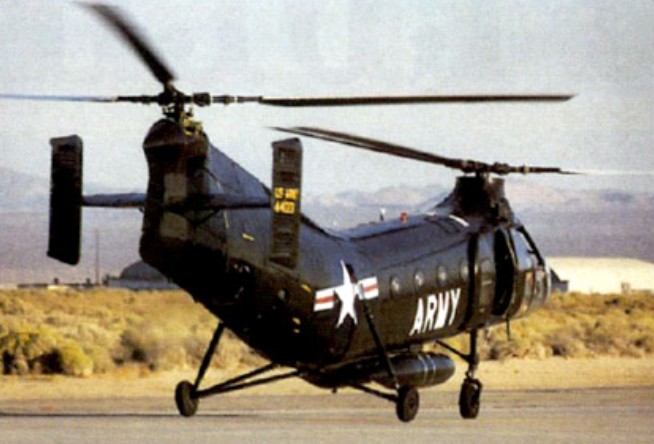
Piasecki set to work on a specification, issued by the US Navy Bureau of Aeronautics in 1945, for a shipboard helicopter to be used on aircraft carriers and larger vessels for SAR, liaison, replenishment and plane guard duties.
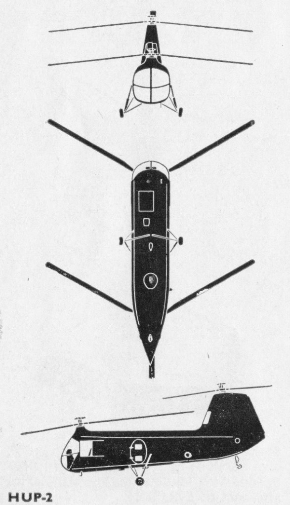
Designated PV-14 (XHJP-1 by the US Navy), two XHJP-1 prototypes (37976 and ’77) were completed for US navy evaluation and three pre-production aircraft, the HUP-1, were ordered in 1948. From 1950-52 a further twenty-two HUP-1 Retrievers (PV-18) were delivered to the U.S. Navy. They differed little from the original XHJP-1, the major apparent change being the addition of inward-sloping endplate fins to the horizontal stabilisers below the rear rotor head. Both sets of 3-blade rotors could be folded for shipboard stowage and the HUP-1, powered by a single 391kW / 525hp Continental R-975-34 piston engine, could accommodate 4-5 passengers or 3 casualty litters in addition to the 2-man crew. The power-plant was installed at the center of the fuselage, which had a steel tube framework with particularly strong, fixed tricycle landing gear. The fin of the HUP-1 was subsequently eliminated, as further improved versions were fitted with an autopilot. The US Navy versions had all-weather instrumentation and some were equipped with sonar for antisubmarine warfare.
XHJP-1 Factory prototype
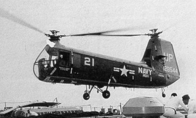
The HUP-1 had a smaller, more compact fuselage than its predecessors. This enabled the helicopter to be stowed without having to fold back the rotor blades. Once acceptance trials were over, the US Navy ordered 32 aircraft including 124588/124594, 124915/124929, 126706/126715, followed by another 165 of the HUP-2, which was fitted with a more powerful engine. The first squadron, HU-2, took delivery of its initial aircraft in February 1951.
Successful tests with a Sperry autopilot in the XHJP-1 enabled the HUP-2, to be built without tail surfaces and the more powerful 410kW Continental R-975-46 was installed in this and all subsequent production models. Another feature of the Retriever was a large rectangular rescue hatch offset to starboard in the floor of the front fuselage, through which a winch inside the cabin could lift weights of up to 181kg / 400 lb at a time. The U.S. Navy machines included some completed as HUP-2S submarine-hunting aircraft with dunking sonar equipment. Another HUP-2 was given a sealed, watertight hull and outrigged twin floats for waterborne tests, presumably as part of the development programme for the Boeing-Vertol 107 / CH-46 helicopter.
Piasecki HUP-2 128543
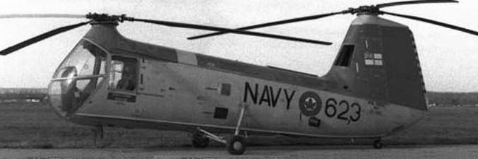
The Marines also used 13 HUP-2, while the Army acquired 70, designated H-25A (serials 51-16572 to -16641) powered by the R-975-46A engine, 50 of which were later transferred to the Navy as HUP-3s, three serving with the Royal Canadian Navy’s Squadron VH-21. One H-25A went to the USN as the HUP-3 prototype; 51-16641=149088.
339 HUP-2 were built (128479/128600, 129418/129522, 129978/130085, 134434/134437), of which some with radar as HUP-2S for anti-sub warfare. Redesignated as UH-25B in 1962.
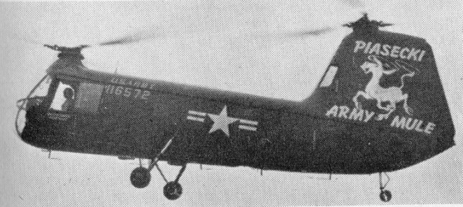
The first H-25A entering regular Army service in early 1953. Those Army Mules that remained in Army service were used mainly as training or medical evacuation aircraft, and the type was totally withdrawn from Army service by 1958.
The Army H-25 Mule was basically similar in general layout to the HUP-2, sharing that aircraft’s all-metal fuselage, fixed three-point landing gear, and 550hp Continental R-975-42 engine. The H-25A differed from the Navy variant primarily in having hydraulically-boosted controls, a strengthened floor with cargo tie-down fittings, and modified doors intended to ease the loading and unloading of stretchers.
Piasecki H-25A Army Mule
In 1951 the U.S. Army ordered a version of the HUP-2 with a reinforced cabin floor and hydraulically boosted controls, for general support and evacuation work. Seventy of these were delivered as H-25A Army Mule from 1953, as were fifty similar Naval HUP-3’s (including three for the Royal Canadian Navy) for ambulance and light cargo duties. Production of the three hundred and thirty-ninth and last aircraft was completed in July 1954. Shortly after this a proposal was made to boost the speed, range and payload of all H-25/HUP aircraft still in service by refitting them with 700hp Wright R-1300-3 engines. However, this did not take place and by the time the new tri-service designation system was introduced in July 1962 only the HUP-2 and HUP-3 remained in service; these became the UH-25B and UH-25C respectively. Neither type is now in U.S. front-line service, and the French and Canadian HUP types were withdrawn from service in 1966.
The 50 HUP-3 built were 147582/147630 and 149088], redesignated as UH-25C in 1962. The last one was former Army H-25A 51-16641.
The HUP-4 has the 800-h:p. Wright R-1300-3 engine, and earlier versions could be modified to that standard.
An amphibious conversion of the HUP-2 was used for research by the Edo corporation in New York. It had a reinforced hull-type lower fuselage, all-metal outrigger floats and a new engine cooling system.
H-25A Army Mule Engine: 550 hp Continental R975-42 Rotor dia: 35 ft Length: 56’11” Weight: 5,750 lb Max. Speed: over 103 mph Range: 340 mi Seats: 6
HUP-1 Engine: 525 h.p. Continental R-975-34 Rotor diameter: 35 ft. Rotors: 2 x 3-blade main rotors in tandem Fuselage length: 32 ft Loaded weight: 5,750 lb Max speed: Over 103 mph Ceiling: Over 10,000 ft Typical range: 395 miles at 80 mph Seats: 6.
HUP-2 Engine: 550 h.p. Continental R-975-46 Rotor diameter: 35 ft. Rotors: 2 x 3-blade main rotors in tandem Fuselage length: 32 ft Loaded weight: 5,750 lb Max speed: Over 103 mph Ceiling: Over 10,000 ft Typical range: 395 miles at 80 mph Seats: 6.
HUP-3 Engines: 1 x 550 hp Continental R-975-42, 410kW Speed: Max: 170 km/h Range: Max 550 km Weight: Empty: 1780 kg Max weight: 2770 kg Rotor diameter: 10.67 m Length rotors turning: 17.35 m Height: 3.80 m Disc Area: 179 sq.m Service ceiling: 3050m Height: 3.80 m Disc Area: 179 sq.m Service ceiling: 3050m
HUP-4 Engine: 800h.p.Wright R-1300-3 Rotor diameter: 35 ft. Rotors: 2 x 3-blade main rotors in tandem Fuselage length: 32 ft Loaded weight: 5,750 lb Max speed: Over 103 mph Ceiling: Over 10,000 ft Typical range: 395 miles at 80 mph Seats: 6.
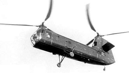
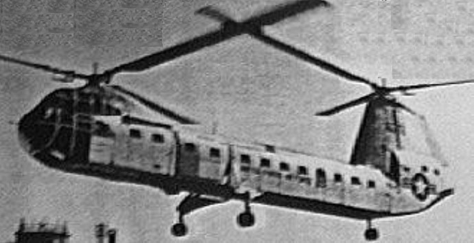
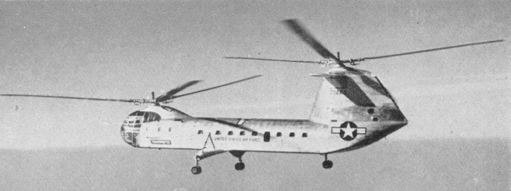
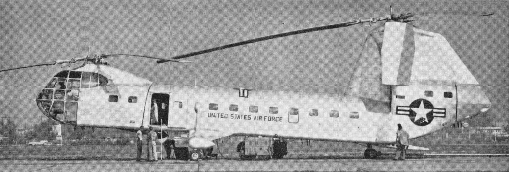
A USAF requirement for a wide-ranging helicopter capable of rescuing downed strategic bomber crews had given rise to the new helicopter. The hefty fuel capacity required to meet its specified 2250km range in part dictated its size. Without the extra fuel, the capacious aircraft also had possible military application as a large troop and cargo transport. In 1946 the Army Air Forces awarded Piasecki Aircraft a contract for the development of a tandem rotor helicopter intended for use in the long-range search and rescue (SAR) role. The resultant Piasecki Model PV-15 was originally given the military designation XR-16 (R denoting rotorcraft under the World War II system), though this was changed to XH-16 in June 1948. The Air Force placed an order for two service test and evaluation aircraft in June 1949, and subsequently allocated the serial numbers 50-1269 and -1270 for these machines.
At the time of its inception the H-16 was the largest helicopter in the world. Though originally intended for the SAR role the Transporter, as the H-16 was ultimately named, evolved during the design process into a heavy-lift craft equipped with a tail loading ramp and optimized for troop and cargo transport. In this role the aircraft could carry up to forty troops or three light trucks within its fuselage, the interior of which was kept clear of obstructions by mounting the engines and all dynamic components in the upper fuselage. The H-16 was also capable of transporting large exterior cargo pods, and was equipped with variable-height landing gear legs in order to accommodate pods of varying sizes.
Piasecki XH-16 50-1269
It had tandem three-blade rotors, and two engines, one at the front and the other in the rear of the fuselage. The rear engine drove the rotor at the top of a tail pylon nearly 4m high. The helicopter had a horizontal stabilizer, to which vertical control surfaces were later added in order to overcome problems of directional stability during fast flight. It weighed 14 tonnes on take-off with two pilots and 40 equipped infantry on board.
It was 23.8m long and topped by two overlapping rotors each 25m in diameter. In-flight vibration was low and of a loping nature. Bonded and tapered all-metal rotor blades (built using a new company process) combined milled-aluminum skins, aluminum honeycomb filler, and a leading-edge balance weight that also served as a mechanical fastener for the skins.
These capabilities appealed to the U.S. Army, which saw in the H-16 an answer to several helicopter mission requirements of its own. It therefore joined the USAF in sponsoring further development of the YH-16.
The first Transporter (serial 50-1269) was powered by two 1650hp Pratt & Whitney piston engines and made its first flight on 23 October 1953 at Philadelphia International Airport, designated YH-16. Company personnel and military officials watched the helicopter take off, hover, and fly forward and sideways during a successful twelve-minute maiden hop flown by Harold Peterson and Phil Camerano.
The Air Force ultimately decided against procuring the H-16 for operational use, and in 1955 the YH-16 was turned over to the Army for evaluation. The Army found the piston-driven Transporter to be underpowered and therefore awarded the reorganized Vertol company a contract for the machine’s conversion to turbine power.
YH-16A second prototype 50-1270
During construction the second prototype (50-1270) was modified to Model PV-45 (first designated H-27 and then H-16A) standard through the replacement of its piston engines with two 1800shp Allison T38-A-6 turboshafts, and modified to carry up to fifty troops, and redesignated YH-16B. The change in powerplants and inclusion of various structural modifications prompted a redesignation to XH-27 in October 1952, though this was changed to YH-16A prior to the aircraft’s first flight in July 1955 with Harold Peterson and George Callaghan at the controls. This aircraft set an unofficial world record of 270km/h in 1956. Both H-16 variants were at times fitted with varying types of experimental horizontal tail surfaces, one of which incorporated large end-plate rudders, but none of these designs were adopted for permanent use.
Despite improvements the type was ultimately judged to be unsuited to sustained operations under field conditions, and the Army terminated the H-16 test programme in mid-1956.
YH-16
In December, the YH-16A broke apart in the air and crashed near the Delaware River, killing Peterson and Callaghan as they returned from a test flight in New Jersey. Investigators determined that the rear rotor shaft had failed, allowing the blades to desynchronize and wobble into the plane of those of the forward rotor. In fact, a frozen bearing in the test instrumentation had precipitated this failure by allowing a steel-tube standpipe, placed within the aluminum rotor shaft to guide wires from the instrumented blades, to undetectably inscribe a deepening groove within the shaft.
This accident caused the H-16 program to be scrapped, preempting the sixty-nine-passenger YH-16B Turbotransporter (a conversion of the YH-16 then in progress), which would have flown with two 3700shp Allison T56 engines. It also preempted Frank Piasecki’s vision of interchangeable under-body pods for the rapid transport of differing loads such as field operating rooms, communications centers, and mobile repair centers. A tall stilt landing gear had already been designed to let the YH-16B accommodate such pods.