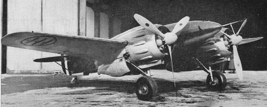
The IMAM Romeo Ro.57, powered by two 840 hp Fiat A.74 R.C.38 radials, entered service in 1942 with home-based elements of the Regia Aeronautica.
A single-seater, it carried an armament of two 20mm cannon and two 112.7mm machine guns in the nose.
The IMAM Romeo Ro.57, powered by two 840 hp Fiat A.74 R.C.38 radials, entered service in 1942 with home-based elements of the Regia Aeronautica.
A single-seater, it carried an armament of two 20mm cannon and two 112.7mm machine guns in the nose.
In the early 1930’s, the Regia Aeronautica put out a requirement for a light reconnaissance aircraft and also a heavier reconnaissance aeroplane. The first should have a 350 km/h (190 knots/220 mph) maximum speed, five hours endurance, three machine-guns and a bomblets dispenser, armour, and the capability to operate from improvised airfields. The heavier one should have a 325 km/h maximum speed, at least 1,300 km (800 miles) endurance, 7,000 m (22,750 feet) ceiling, climb to 5,000m (16,000) in 19 minutes, three crew, five weapons, high wing and other details.
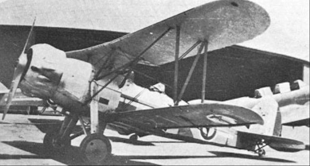
IMAM designed a new aircraft, the Romeo Ro.37, which first flew in 1933. The aircraft was an unequal-span single-bay biplane of mixed wood and metal construction. Its design included fixed tailwheel landing gear, all three wheels being provided with spats; a braced tail unit incorporating a variable-incidence tailplane; and accommodation for two in tandem enclosed cockpits, Power was provided by a 522kW Fiat A.30RA Vee engine of 560hp. It reached 300 km/h (162 knots). An improved Ro.37bis was developed subsequently, and this introduced an optional radial powerplant comprising either the Piaggio P. IX or P.X supercharged engine. The better reliability of this engine was considered more desirable and so this was the main version produced.
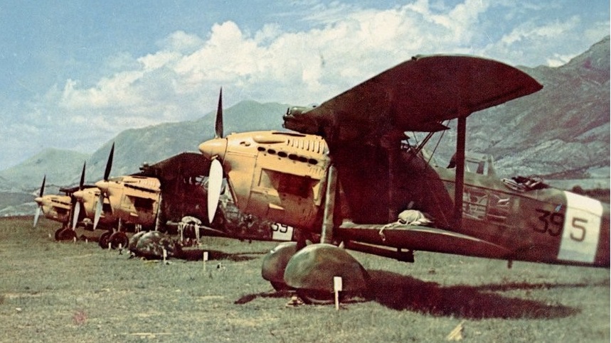
Both models proved popular for their day, with production of the Ro.37 and Ro.37bis exceeding 160 and 475 respectively. Ro.37 were exported (ten to Uruguay, sixteen to Afghanistan, fourteen to Hungary, eight to Austria, and one to Ecuador) and around 280 were in service with the Regia Aeronautica in 1940 in thirty squadrons.
IMAM also built a successor to the Ro.37, the Ro.45. This was an enhanced Ro.37 that first flew as a prototype on 10 December 1935. The 820 hp Isotta-Fraschini Asso XI.RC40 engine boosted maximum speed slightly to 217mph, increased the ceiling to 26,200 feet, and endurance to 1,398 miles. Destined for long-range reconnaissance and light bombing, it remained a single prototype.
The Ilmavoimat / Maavoimat evaluated both the Ro.37 and the single Ro.45 prototype but considered the design unsuitable for their overall requirement.
Ro.37 and Ro.37bis aircraft were involved in the Spanish Civil War from October 1936, when the first 10 arrived. Another 26 (possibly 58) went to this theatre and were used for many missions and tasks. They were used as assault aircraft, even though they were unarmoured. The results were satisfactory and some were even converted to a single-seat machine for use as attack fighters. The two-seat versions were used as heavy fighters, providing protection for S.81 bombers from Republican I-15s. It is not known if there were any air-to-air victories. They were also used extensively by the Regia Aeronautica during Mussolini’s invasion of Abyssinia between October 1935 and May 1936 and during the Italian occupation of that country until 1941. Some 275 Ro.37bis aircraft were in service with the Regia Aeronautica when Italy became involved in World War II, and these saw first-line service in the East and North African campaigns and in the Balkans. Some were in service up to 1943 and perhaps even later. They were very vulnerable, but in the war Italy did not have sufficient resources to produce a better observation aircraft, not even the Ro.63, a superior aircraft, similar to the Storch, but with more endurance. After withdrawal from first-line service they found a variety of uses, but all had been retired before Italy’s armistice with the Allies on 8 September 1943. The aircraft was produced until 1939 with a total of 569 (237 + 332bis) produced.
The remnants of the Ro.37’s sold to Afghanisatan were found northeast of Kabul by the Italian Army’s 132nd Artillery Regiment “Ariete”.
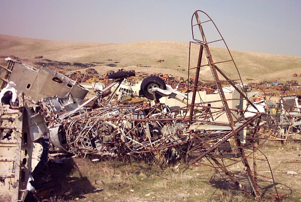
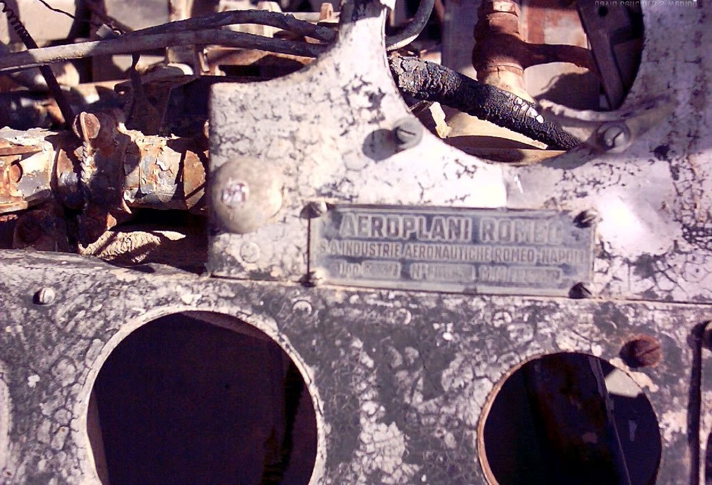
Of the 16 Ro.37bis sold to Afghanistan in 1938, 6 relics were recovered by an Italian / US team to the North East of Kabul and one of them is exhibited at Vigna di Valle Museum waiting to be completely restored.
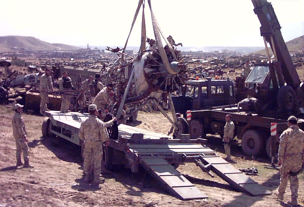
Tom Martin, LTC of the US Army, was the garrison commander at the Kabul Military Training Center and “neighbor” to the Italian garrison at Camp Invicta. Their garrison commander, LTC Mauro D’ Ubaldi, and Martin became friends through mutual security needs and engineer projects. D’ Ubaldi approached Martin and asked if he would help his team come onto our site and remove from the boneyard the a plane. They also recovered wings and there were scraps of material with paint on some of the parts which showed the material and colors.
Ro.37
Crew: 2
Engine: Piaggio P.IX RC.40, 560 hp (418 kW)
Maximum speed: 205mph
Range: 696 miles
Service ceiling: 23,620 ft
Armament: three machine guns (two in nose / one flexible mount rear cockpit)
Bombload: 397 lb (180kg) of bombs (twelve x 15 kg bombs) on underfuselage racks
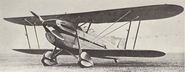
The Romano R-80.01 first prototype was a private venture by Etienne Romano, and was designed to provide an aerobatic two-seat biplane for company pilot Lemoigne to demonstrate at air shows. Tested in early 1935, it was also flown with great success by Michel Detroyat. Its design features included the provision of ailerons on both wings, robust divided landing gear, and a 179kW Lorraine 7Me radial engine in a NACA cowling. After testing also by the official STAe, the R80.01 then gave many aerobatic shows with Lemoigne at the controls.
In response to official suggestions, R-80.02 with the more powerful Salmson 9Aba engine was first flown in March 1936 and exhibited at the Paris Salon de I’Aeronautique of that same year. It incorporated changes already made on the aerobatic prototype, including ailerons on the lower wings only and a fin of increased area. Intended as a two-seat dual-control intermediate trainer, it was soon redesignated R-82.01. Two further protoypes were built, both of them being sold to private owners, one of them the well-known aviatrix Lucienne Saby.
Meanwhile, Romano had become part of the nationalised SNCASE and Michel Detroyat became Inspector of Flying Equipment for all the nationalised companies. On the latter’s urging, large orders were placed by the state for R-82 trainers for the Armee de I’Air. In the event, the total of production aircraft was 147, to which was added a further 30 ordered in 1937 by the Aeronavale. Series trainers featured a number of refinements and some simplifications, the principal external change being the introduction of a long-chord engine cowling.
By 1 August 1939 70 R-82s had been taken on charge, and all 177 series aircraft had been delivered by May 1940. The R-82 have excellent service with the Armee de I’Air and Aeronavale, largely equipping the Centres d’lnstruction and Ecoles de Pilotage.
In February 1938 two R-82s were purchased by a French intermediary company and ferried to Spain, where they were used for training and liaison duties by the Republican government fighting the Nationalist forces. It is uncertain whether these were new aircraft or machines taken from Armee de I’Air contracts.
R-82
Engine: 1 x Salmson 9Aba radial piston engine, 209kW
Wingspan: 9.88 m / 32 ft 5 in
Length: 7.82 m / 26 ft 8 in
Height: 3.34 m / 11 ft 11 in
Wing area: 23.72 sq.m / 255.32 sq ft
Max take-off weight: 1328 kg / 2928 lb
Loaded weight: 918 kg / 2024 lb
Max. speed: 240 km/h / 149 mph
Ceiling: 6500 m / 21350 ft
Range: 660 km / 410 miles
SIM-XIV-H – coastal scout (one prototype in 1938 and 6 copies in 1939)
SIM XIVB-H – bomber seaplane (12 copies in 1940)
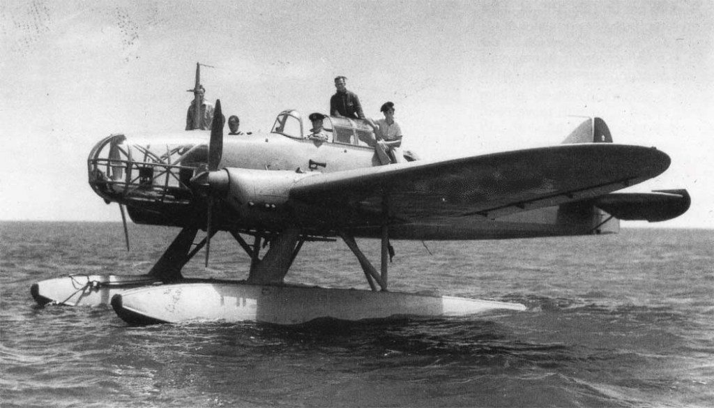
The Yugoslav Royal Air Force turned to the Rogožarski factory for seaplane pilot trainers in 1937. A requirement was the seaplane would match the characteristics of the SIM-X. Since it was not possible to adapt existing SIM-X for installation of EDO floats, chief designed Sima Milutinović fitted the new, larger plane with a more powerful Walter Major 6 190 hp engine. At the end of 1937 the prototype was ready for testing. The first flight was conducted on February 7, 1938, by test pilot Ivan Koroša in at Divulje. After the flight tests had achieved satisfactory results, the first batch of aircraft was ordered, which were delivered in mid-1939.
The SIM-XII-H two-seat plane, with engine Walter Major 6 (190 hp), was of predominantly wooden construction, with an elliptical cross-section of fuselage entirely made of wood and covered with plywood. The wings were wood covered with fabric, with rounded ends. On each side, the wings are supported by a pair of inclined struts attached to the fuselage. The fuel tank was located in the central section between the wings. The first series of aircraft had two EDO Model 47 floats installed.
Nine were built in total.
The Royal Maritime Navy signed a contract with the Rogožarski factory on July 15, 1940 for a second series of these plane (4 aircraft) with these seaplanes equipped for instrument, or, “blind” flying. Rogožarski delivered these aircraft in five months but without floats as the delivery from Canada was delayed for several months. With agreement reached between the Rogozarski factory an the Navy command, the design and development of domestic aircraft floats was launched, unfortunately this project did not reach completion due to the outbreak of April war . In the pre-war period two SIM-XII-H aircraft were in accidents both in Boka Kotorska in 1940. Both aircraft were designated for disposal, so the Navy Command requested approval to install the floats from these planes onto new aircraft (onto the 2nd series of SIM-XII-H) considering that these planes were equipped with instruments for instrumental (“blind”) flying. When the approval was given, the floats were installed into new planes, so the aircraft in the second series in use before the war broke out.
The type was retired in 1941.
Rogožarski SIM-XII-H
Engine: 1 × Walter Major 6, 6-cylinder line, 140 kW (190 hp)
Propellers: 2-bladed
Length: 7.50 m (24 ft 7 in)
Wingspan: 11.00 m (36 ft 1 in)
Height: 2.96 m (9 ft 9 in)
Wing area: 2,050 m2 (22,100 sq ft)
Empty weight: 635 kg (1,400 lb)
Gross weight: 920 kg (2,028 lb)
Maximum speed: 208 km/h (129 mph; 112 kn) at sea level
Range: 840 km (522 mi; 454 nmi)
Crew: 2
single-seater fighter (12 copies – serial production in 1940)
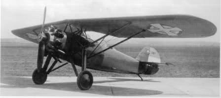
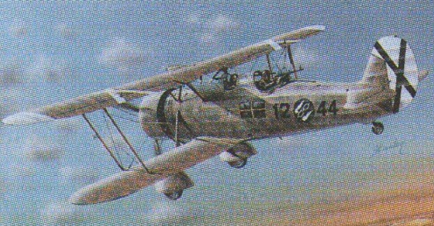
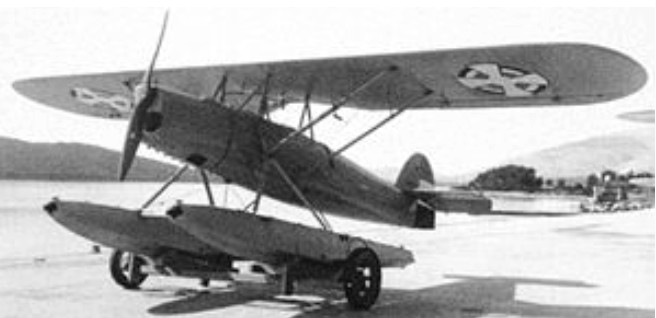
The Rogozarski PVT (Рогожарски ПВТ in Serbian, translated as Rogozarski PWT in German and as Rogojarsky PVT in some older English sources) was a single-engined, two-seat parasol winged aircraft designed as an advanced and fighter trainer in Yugoslavia before World War II.
In about 1933 the Rogozarski team of Rudolf Fizir, Sima Milutinović, Kosta Sivčev and Adem Biščević designed the PVT, a training aircraft with tandem open cockpits in an oval wooden monocoque fuselage. Its wooden, canvas covered wings were swept and parasol mounted well above the fuselage with pairs of lift struts to the lower fuselage and a central inverted V cabane. They carried long narrow chord ailerons, with prominent spades well clear of the upper surfaces
Sixty-one were built between 1935 and 1941, serving with the Yugoslav Royal Air Force until the fall of Yugoslavia in 1941. After that, some PVTs were used by the newly formed Croatian Air Force, sometimes as ground attack aircraft.
One PVT was converted to a PVT-H interim seaplane trainer. Three new PVT-H were built in 1937.
Engine: 1 × Gnôme-Rhône 7K, 310 kW (420 hp)
Wingspan: 11.20 m (36 ft 9 in)
Wing area: 22.1 sq.m (238 sq ft)
Length: 8.54 m (28 ft 0 in)
Height: 2.81 m (9 ft 3 in)
Empty weight: 967 kg (2,132 lb)
Gross weight: 1,213 kg (2,674 lb)
Maximum speed: 240 km/h (150 mph; 130 kn) at sea level
Service ceiling: 7,000 m (22,966 ft)
Rate of climb: 6.54 m/s (1,287 ft/min) to 2,000 m (6,562 ft)
Crew: 2

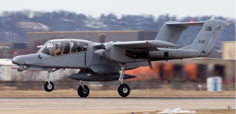
To meet a US Navy requirement for a light armed recon¬naissance aircraft, North American Rockwell produced their NA-300 design submission for the OV 10A Bronco. A contract for seven YOV-10A prototypes was placed in 1964, the first of them flying on 16 July 1965.
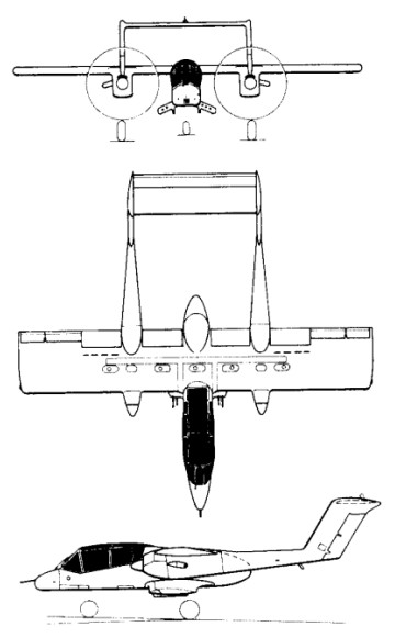
With a two-seat fuselage nacelle mounting a high-set monoplane wing, the aircraft had twin tailbooms extending aft from the nacelles of the two turboprop engines, each with a fin and rudder, and interconnected by a tailplane/elevator assembly. The main units of the tricycle landing gear retracted into the engine nacelles.
North American / Rockwell OV-10 Bronco Article
Six of the prototypes were powered by 447kW Garrett T76-G-6/8 engines, but had one Pratt & Whitney YT74-CP-8/10 turboprops for comparative evaluation.
The OV-10A Bronco production version had a 3.05m increase in wing span and more powerful T76-G-10/12 engines, the first flown on 6 August 1967, and 114 were built for the US Marine Corps.
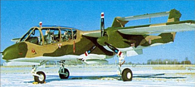
These were followed by 157 similar OV-10As for the US Air Force, these entering operational service in Vietnam in 1968. Under the US ‘Pave Nail’ programme, 15 were provided with special equipment for the location and illumination of targets by night. Other versions have included six OV-10B aircraft supplied to Germany as target tugs, followed by 18 turbojet-boosted OV-10B(Z) aircraft for the same role. Versions similar to the OV-10A have been supplied to Indonesia (16), Thailand (40) and Venezuela (16), under the respective designations OV-10F, OV-10C and OV-10E, and six US OV-10As have been transferred to the Royal Moroccan air force.
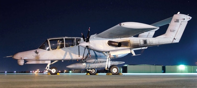
Two OV-10As were modified under a US Navy contract of 1970 to YOV-10D NOGS (Night Observation/Gunship System) aircraft to provide the US Marines with advanced night operational capability. Since evaluation of these aircraft, 17 US Marine Corps OV-10As have been converted to OV-10D NOS (Night Observation Surveillance) configuration, now equipped with a FLIR (forward-looking infra-red) turret in the nose linked to an underfuselage 20mm cannon turret, and a laser target illuminator.
Production of the Bronco for the USMC, USAF, and four export customers was completed in 1980.
Able to carry a maximum weapon load of 3,600 lb (1,633 kg), the Bronco has proved valuable for Forward Air Control (FAC) operations in South East Asia.
Of the seven prototype North American Rockwell OV 10 Broncos built, No.3 on the line was heavily modified and was the only short-wing example of the aircraft ever built. YOV 10A 152881 (N718NA) has a wingspan of only 32ft (9.75m), whereas standard production aircraft had 40ft (12m) of wing. From 1966 to 1972 the aircraft was used as a demonstration airframe and was used to take Admirals, Generals and Congressmen for flights to extol the virtues of the twin engined observation and forward air controller design. The Bronco was also assigned to train new pilots on the gunnery ranges, using its machine guns and rockets. During the spring of 1972 it was assigned to NASA under the Department of the Army, for STOL flight testing. This was carried out at the Ames Flight Test Center in California, with the aircraft being allocated a civilian registration.
During its time at Ames, the Bronco was heavily modified, the aircraft’s Garrett T 76 turboprops were removed and replaced by Lycoming T 54s. Three blade 7ft (2.1m) Hamilton Standard propellers were replaced with 10ft (3m) four bladed Curtiss Electric composite propellers, and the engines were interconnected by a single solid shaft in the leading edge of the wing. With this system in operation, the aircraft flew at 47 knots and NASA was working toward getting the minimum speed down to 30 knots. The Bronco became unstable, and the programme was stopped. The aircraft was with NASA until it was sold to the Detroit Institute of Aeronautics in 1979.
OV-10A
Engines: 2 x Garrett AiResearch T76-G-416/417, 715 shp
Wing span: 40 ft 0 in (12.19 m)
Wing area: 290.951 sqft / 27.03 sq.m
Length: 41 ft 7 in (12.67 m)
Height: 15 ft 2 in (4.62 m)
Max TO wt: 14,446 lb (6563 kg)
Weight empty: 6892.8 lb / 3126.0 kg
Max level speed: 281 mph (452 kph)
Cruising speed: 168 kts / 312 km/h
Service ceiling : 27001 ft / 8230 m
Maximum range: 1199 nm / 2220 km
Range (max. weight): 410 nm / 760 km
Crew: 2
Armament: 4x MG 7,62mm M60C/500rds., 1633kg ext. 5pts.
OV-10B
Engines: 2 x Garrett T76-G-418
OV-10D
Engines: 2 x Garrett T76-G-420/421 turbo-prop, 776kW / 1040 shp
Max take-off weight: 6552 kg / 14445 lb
Empty weight: 3127 kg / 6894 lb
Wingspan: 12.19 m / 39 ft 12 in
Length: 13.41 m / 43 ft 12 in
Height: 4.62 m / 15 ft 2 in
Wing area: 27.03 sq.m / 290.95 sq ft
Ceiling: 9145 m / 30000 ft
Range w/max.payload: 740 km / 460 miles
Bombload: 2000kg
Crew: 2

The Rockwell B-1 resulted from a November 1969 requirement for a medium-altitude with dash capability of Mach 2.2+ for the high-speed delivery of free-fall and stand-off nuclear weapons. Submissions were received from several companies, Rockwell’s design being selected in 1970 as the B-1A. The full-scale design and development programme for the initial production version was soon under way. The initial model was a complex and highly advanced variable-geometry type with General Electric F101 turbofans and fully variable inlets for maximum capability in all elements of the flight envelope.
The first of four prototypes (71-40158) of the Rockwell International B-1 four-turbofan strategic heavy bomber made its maiden flight on 23 December 1974; designed to meet USAF Strategic Air Command’s Advanced Manned Strategic Aircraft (AMSA) requirement, it incorporated variable geometry wings (maximum sweep of 67 degrees), accommodated a four-man crew and had an estimated maximum speed of Mach 2 at altitude.
In June 1977 President Carter decided to scrap the programme in favour of cruise missile development although flight trials with the B-1A aircraft were to be continued for research purposes, the flight testing continued through 1981 with the four prototypes.
Then with the inauguration of President Reagan matters began to look up again, the new administration deciding during October 1981 to procure 100 examples of a much revised B-1B version in the low-level penetration role for high-subsonic delivery of free-fall and stand-off weapons. The B-lB was.therefore a straightforward but nonetheless major adaptation of the B-1A optimized for the low-level transonic role with fixed inlets and revised nacelles (reducing maximum speed to Mach 1.25). But it did have a strengthened airframe and landing gear for operation at higher weights with nuclear and conventional weapons over very long ranges. Other changes were concerned with reduction of the type’s already low radar signature, S-shaped ducts with streamwise baffles being adopted to shield the face of the engine compressors and radar absorbent materials being installed in sensitive areas to reduce electromagnetic reflectivity. The second and fourth B-lAs were used from March 1983 to flight-test features of the B-1B, which first flew in September 1984 with the advanced offensive and defensive electronic systems.
In conjunction with the USAF, Edwards AFB, ASA Dryden Flight Research Center carried out two six-hour flights of the B-1, with the first taking place on 25 March 1981. B-1 number 3, part of the USAF/Rockwell joint test force Bomber Penetration Evaluation was utilised for the two flights. The two supersonic flights evaluated the Structural Mode Control System.
The first production B-1B flew on October 18, 1984, some five months ahead of schedule. Two B-1A development aircraft had previously been converted to B-1B standard, the first flying in B-1B form in March 1983. Production deliveries began in July 1985, to replace B-52Hs in the penetration role, and will continue until 1988.
The ninth B-1B was the first to be fitted with a moveable bulkhead in the forward weapons bay, enabling it to carry eight AGM-86 air-launched cruise missiles (ALCM), short-range attack missiles (Sram), and extra fuel tanks internally. Maximum ALCM loading is eight missiles internally and 14 externally on eight underfuselage hardpoints.
Initial Operational Capability was first achieved on 1 October 1986.
In January 1987 a B-1B successfully launched a short-range-attack missile for the first time, while in April an aircraft from the 96th Bomb Wing at Dyess AFB, Texas, completed a 2l hr 40min mission including five in-flight refuellings (to maintain a high aircraft weight), covering a distance of 15,145km (8,175 nm).
The final B-1B was delivered 2 May 1988.
In 1989, when Neil Armstrong became chairman of AIL Systems Inc., he was invited to fly the B-1 bomber. He later flew the B-1 again for the first flights television series.
The B-1B Lancer were modified and aircrews were trained for the use of conventional weapons, including stand-off and laser guided weapons, and did flew combat missions during Operation Desert Fox.
Also in 1999 the B-1s flew bombing missions using conventional weapons against Yugoslavia as part of Operation Allied Force.

B-1B
Powerplant: four 136.92 kN (30,780 lb st) General Electric F101-GE-102 afterburning turbofans
Length 44.81m (147 ft 0 in)
Height 10.36m (34 ft 10 in)
Wing span (fully swept 67 deg) 23.84m (78ft 2½ in), (fully spread 15 deg) 41.67 (136 ft 8½ in)
Wing area: 181.16 sq.m / 1949.99 sq ft
Empty, equipped weight 87091 kg (192,000 lb)
Max Take-Off Weight 215.365 kg (477,000 lb)
Fuel internal: 91,000 lt
Max level speed at high altitude Mach 1.25 or 1324 km/h (823 mph)
Penetration speed at 61m (200 ft) Mach 0.9 or 965 km/h (600 mph)
Service ceiling above 15,240m (50,000 ft)
Armament: up to 34020 kg (75,000 lb) of ordnance / 22 AGM 86B (Cruise Missile) / 38 SRAMS
Internal weapon bays; 3
Range internal fuel: 6480 nm / 12000 km / 7457 miles
Air refuel: Yes
Crew: 4


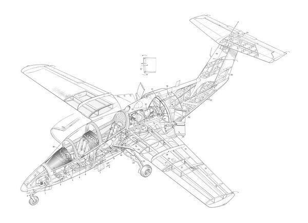
The project was initially a cooperative one with Grumman American, GA supplying wings and empennage, for the most part off the shelf Cheetah parts, and retaining an option to market the airplane in the U.S. RFB has been responsible for design, development and certification. The second prototype embodied improvements in duct and fan technology and a somewhat larger airframe; it was the prototype that will be used for certification in Germany, from which, under reciprocal agreements between the two countries, FAA certification will more or less routinely follow. Grumman declined the marketing option in January 1977, but there is a continuing agreement between the two firms to explore the possibilities of ducted fans.
RFB / Rhein-Flugzeugbau Fantrainer Article
Luigi Colani ended up designing the entire forward fuselage and cabin a fiberglass and plexiglass shell grafted onto a simple keel upon which the entire airplane is built. The pilot and single passenger recline in an elegantly streamlined shell at the front of the airplane. Behind them is a smallish luggage space precisely like that in a small sports car, right down to the transmission tunnel hump provided by the keel structure. A well padded firewall separates the cabin from the engine compartment, the tubular spar of the GA wing. Wings and gear are from a Grumman Cheetah. Reconfigured from a low wing to a mid body location.

The engine is a two rotor NSU Wankel of 150 horsepower. It is water cooled and uses a double automotive ignition system of the battery/generator/coil/distributor type. The Wankel comfortably delivers its peak power at about 6,000 rpm, and the ducted fan allows it to turn at that speed regardless of the forward speed of the airplane.
Rather than take advantage of the ability of the fan to operate efficiently at high speed to eliminate the need for reduction gearing; RFB found that the noise produced by the small, multi-blade, fast-turning fan was so unbearable that they had to turn to a larger three blade version geared down to turn at about half the speed of the engine.
The fan itself is simply a fixed pitch propeller with broad, stubby blades of rather complicated shape. The optimum design has not yet been found, but it is thought that replacing the blades with a scimitar shaped type will further reduce noise at no cost in thrust. The circular duct enclosing the propeller counteracts the natural inefficiency of a stubby blade, which, like a stubby wing, tends to produce a lot of drag along with its lift.
The engine is cooled by radiators behind and below the cabin, with almost invisible flush air inlets be-neath the aft fuselage, exhaling into the fan duct. Cabin heat (not satisfactory on the prototype) is provided, as in most cars, by pumping some of the engine cooling water through a heat exchanger in the cabin air inlet.
The composite-construction Fantrainer first flew in October 1973 powered by two Wankel rotary engines.
Subsequent aircraft have used a single Allison 250 turboshaft to drive a Dowty Rotol five-blade constant-speed ducted fan. Its 150hp, water cooled Wankel engine drives a 43 inch, three blade, shrouded fan, which is located directly behind the two seat cabin. The tail cone is not a cone; instead, it consists of intersecting vertical and horizontal beams whose caps pass around the fan, and at whose intersection is a slender, tapering tube the “cone”. The empennage is a “T” arrangement with a swept vertical.
The RFB AWI 2 Fantrainer first prototype (98+30) was flown for the first time on 27 October 1977. Two prototypes of this tandem two seat trainer had been ordered by the Federal German defence ministry for evaluation as a potential replacement for the Piaggio P.149D primary trainers in Luftwaffe service.
The RFB Fantrainer, flown in AWI 2 and ATI 2 prototype forms, was in production in 1984 as the Fantrainer 400 and Fantrainer 600 with 420 shp (313 kW) and 650 shp (485 kW) Allison turboshafts for the Royal Thai air force. All but six of the 31 Fantrainer 400s and 16 6Ws were assembled in Thailand.
The Royal Thai Air Force is to receive 31 Fantrainer 400s and 16 more-powerful Fantrainer 600s. All but four are to be assembled in Thailand from kits supplied by RFB but using Thai designed and built metal wings in place of the original GRP units. The Thai aircraft will have four underwing weapons pylons. The first two German-built aircraft were delivered in October 1984, but the license-assembly programme has suffered a number of delays, particularly associated with production of the metal wings. To expedite deliveries, a number of Thai-assembled aircraft have been completed using German-supplied GRP wings. Thai aircraft also have a revised cockpit, Alkan stores management, and Stencel Ranger rocket assisted escape systems.
Two production models were offered, the Fantrainer 400 with the Allison 250-C20B 420 shp engine, and the Fantrainer 600 with a 650 shp Allison 250-C30 power plant.
Lufthansa also selected the type for its pilot training school.
Projected Fantrainer 800 did not enter production; neither did the proposed Tiro-Trainer with a turbofan engine.
Fantrainer 400
Engine: 1 x Allison 250 turboshaft, 420 shp
Fantrainer 600
Engine: 1 x Allison 250-C30 turboshaft, 600 shp
Span: 9.7 m
Length: 9.5 m
Height: 3.2 m
Wing area: 150.696 sq.ft / 14 sq.m
Empty wt: 2557.8 lb / 1160 kg
MTOW: 2300 kg
Warload: 800 kg
Max speed: 430 kph
Landing speed: 61 kts / 113 km/h
Cruising speed: 200 kts / 370 km/h
Initial ROC: 960 m / min / 2952.76 ft/min / 15.0 m/s
Service Ceiling: 25000 ft / 7620 m
T/O run: 200 m
Ldg run: 270 m
Fuel internal: 475 lt
Range: 1390 km
Endurance: 4.8 hr
Crew: 2