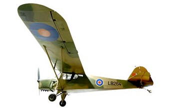
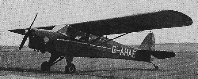
This design originated with a pre-war American light cabin monoplane of 1938 built in England under licence. Successful trials with impressed civilian Taylorcraft Plus D aircraft by the Army for artillery spotting duties led to the introduction of the first fully militarised Taylorcraft, the unarmed two-seat Auster I.
One hundred were built, entering service with No 654 Squadron in August 1942 as the first fixed wing aircraft in British Army service and along with the succeeding Auster marks III, IV and V they served in with the Desert Air Force in North Africa, and in Sicily, Italy, and with the 2nd Tactical Air Force from Normandy to Germany in 1944-45, flown by British Army officers trained by the RAF. The survivors were sold out of front-line service by 1946, though the Fleet Air Arm operated a few in second-line units.
Engine: 90-hp/67-kW de Havilland Cirrus Minor I Wingspan: 36 ft Length: 22 ft 11 in Empty weight: 125 mph Loaded weight: 1400 lb Max speed: 125 mph Cruise: 107 mph ROC: 1000 fpm
Born out of the South African Air Force’s need for an escort and close air support helicopter, the Rooivalk programme was initiated in the early 1980s by Atlas Aviation. The Alpha XH-1 was purely a test-bed for weapon and cockpit systems. It was fitted with a GA-1 Rattler 20mm cannon in a steerable turret, linked to a Kukri helmet-mounted sight. Following on from the Alpha XH-1 research, Denel comimssioned two Puma helicopters to develop the systems required for the Rooivalk. During 1987, the first of two XTP-1 Puma-based test-beds were built and used to evaluate engines, avionics, optronics, weapons and associated control systems for the larger airframe. These test-beds also included the use of locally-produced composite materials used in both airframe and rotor systems. Puma J1 first flew in 1986 and was the primary avionics, weapons and flight control systems’ test bed.
A highly modified version of the Aérospatiale SA.330 Puma, the XTP-1 has been under development since 1981, and a prototype was revealed in May 1987. Principal upgrades include the installation of an under-fuselage GA-1 20mm cannon turret with a helmet-mounted sight for the gunner and internal ammunition storage, two large stub wings with a total of four pylons for rocket pods, and a redesigned tail unit with a ventral fin and modified horizontal stabiliser.
Puma J2 flew shortly afterwards, its primary task being to develop the weapons systems and integrate them with the aircraft and the other on hoard systems. Concurrently two missile tests were conducted: the first studied the effect of missile blast on the tail boom and the other studied the accuracy of the weapons and associated systems.
The first Rooivalk prototype was unveiled in January 1990 and the second prototype, or advanced design model, flew for the first time in May 1992. It differed from the original experimental design model in having the production 1553B databus and full anti-armour mission equipment fitted. It was also armed with the 20mm cannon fitted in a TC-20 chin turret.
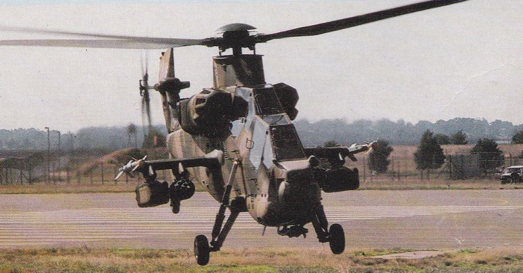
From the J model Pumas the Rooivalk started to take shape in the form of the initial experimental development model (XDM). XDM first flew on 11 February 1990 and began testing aircraft dynamics before progressing on to validate mechanical, aerodynamic and structural design, moving through to expand the flight envelope. It is fitted with an articulated rotor head which allows it to loop, giving it that per¬formance edge over an adversary. Denel also claims that the maximum speed was taken out of the design envelope allowing 196kt in forward flight.
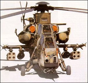
The Rooivalk’s fuselage is mostly metal but with some composites. It has stepped tandem cockpits, with the pilot in the rear and the co-pilot/gunner in the front. The cockpit canopies are formed from flat plate on single curvature sheets to minimise glint from the sun. The twin Topaz turboshaft engines are uprated versions of the Turbomeca Turmo IV and the main rotor is similar to that fitted to the Aerospatiale Puma. An automatic flight control system is fitted, with auto-hover and auto-land. The Rooivalk is designed to operate at low level (under 15m) and at high speeds.
This tandem-seat helicopter is based around a Puma transmission and dynamics and has been built using composite materials. Powered by two Turbomeca Makila turboshafts developing 1175kW it has an all-up-weight of 3245kg. The helicopter can be armed with an assortment of weapons and is capable of operating day or night. Weapons include: 20mm cannon fitted in a TC-20 chin turret or larger DEFA 30mm cannon in a TC-30 chin turret, 2 x 18-tube rocket pods, 2 box launchers for 4 laser beam-riding ZT-35 anti-tank guided missiles, 2 Kukri or Darter Infra-Red homing air-to-air missiles.
The South African Air Force purchased four Rooivalk CHS-2s in 1993 and intend to eventually operate a Squadron of at least 16 Rooivalks. The Rooivalk entered service in late 1996.The Rooivalk was also offered to the British Army to fulfil their Attack Helicopter requirement.
By 1999 was called the Red Hawk.
CSH-2 Engine: 2 x Turbomeca Makila 1A2, 1470kW. Instant pwr: 1492 kW. Rotor dia: 15.58 m. Length with rotors turning: 18.73m Fuselage length: 16.4m Height: 4.59m Empty weight: 5910kg MTOW: 8750 kg. Payload: 2030 kg. Max speed: 167 kt / 309km/h Max cruise: 150 kt / 278km/h Max range (internal fuel): 700 km. Range with max fuel: 705km Range MTOW with external fuel: 1260km Service ceiling: 6100m HIGE: 18,200 ft. HOGE: 16,500 ft / 5545m Crew: 2
Engine: 2 x Topaz (Turboméca Makila 1K2), 1794 shp Rotor diameter: 51.115 ft / 15.58 m Length: 54.626 ft / 16.65 m Height: 17.028 ft / 5.19 m Max take off weight: 19293.8 lb / 8750.0 kg Weight empty: 13031.6 lb / 5910.0 kg Max. speed: 167 kt / 309 km/h Cruising speed: 150 kt / 278 km/h Initial climb rate: 2198.82 ft/min / 11.17 m/s Service ceiling: 16503 ft / 5030 m Maximum range: 680 nm / 1260 km Range: 378 nm / 700 km Endurance: 4 h Crew: 2 Armament: 1x MG 20mm, 8-16 Miss. ext., 4x A/A Miss. V3B Kukri, max. 2030kg
The Atlas Cheetah came about through a need by the South African Air Force to update / replace its series of aging fighters while its bordering neighbors were receiving updated Soviet Bloc aircraft. Embargos limited the options available and the decision was made to modify existing SAAF Mirage III’s to a new standard.
It is believed that Atlas received some level of assistance from IAI of Israel. This brought the South African Mirage III to a new standard, implementing various proven Israeli avionics and computer systems and to the airframe, canards.
Though retaining roughly 50 percent of the existing Mirage III airframe, the Cheetah was basically an all-new aircraft. The aircraft would appear in a few variants including single-seat and twin-seat derivatives. A static inflight refueling probe was added and additional underfuselage hardpoints (wingtip hardpoints were trialed successfully for the Mirage IIIR2Z which would have become the “Cheetah R” dedicated reconnaissance platform but these never put into production). More powerful engines were also added.
Armament was centered around twin 30mm DEFA cannons and air-to-air and air-to-surface munitions of various types. The definitive Cheetah would become the single seat “Cheetah C”.
The first Cheetah conversion was revealed in July 1986, and resembles the IAI Kfir in appearance, although Atlas denies any overseas assistance with the programme. Intake mounted canards and dog-tooth leading edges are among a number of structural modifications which, together with upgraded flight systems, significantly improve the aircraft’s manceuvring performance.
Mirage 3/5/50, some having been upgraded to Cheetah standard. There are about 16 Cheetah-E conversions (all out of service); 38 Cheetah-C conversions; 16 Cheetah-D conversions; and one Cheetah-R conversion.
The Cheetah is set to be replaced in the South African Air Force beginning with the arrival of the Saab JAS J39 Gripen, of which an initial batch were ordered in 1999.
Atlas Cheetah EZ Engine: 1 x SNECMA Atar 9C turbojet, 13,670lbs thrust with afterburner. Length: 50.85ft (15.5m) Wingspan: 26.97ft (8.22m) Height: 14.76ft (4.50m) Empty Weight: 14,568lbs (6,608kg) Maximum Take-Off Weight: 30,203lbs (13,700kg) Maximum Speed: 1,453mph (2,338kmh; 1,262kts) Maximum Range: 746miles (1,200km) Rate-of-Climb: 8,666ft/min (2,641m/min) Service Ceiling: 55,774ft (17,000m) Armament: 2 x 30mm DEFA 552 cannons Hardpoints: 7 Crew: 1
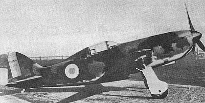
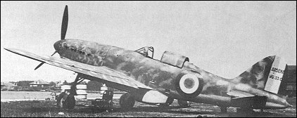
Developments of the VG 33 under test in 1940 included the VG 34, flown on 20 January 1940 with a 910hp Hispano-Suiza 12Y45 engine, and the VG 35 with a 1000hp Hispano-Suiza 12Y51 which flew on 25 February 1940. The VG.35 attained a maximum speed of 575km/h at 6200m during tests, and the airframes and armament of both the VG 34 and VG 35 were identical to those of the VG 33. The VG 36 flown on 14 May 1940, had the 1000hp HS12Y51 of the VG 35, but included some redesign of the rear fuselage with a shallower, wider faired radiator bath. Armament of the VG 36 comprised one 20mm HS 404 cannon and four 7.5mm MAC 1934 M39 machine guns.
VG 36 Wingspan: 10.80 m / 35 ft 5 in Length: 8.10 m / 26 ft 7 in Height: 3.31 m / 10 ft 10 in Wing area: 14.00 sq.m / 150.69 sq ft Max. speed: 590 km/h / 367 mph Ceiling: 7000 m / 22950 ft Range: 1100 km / 684 miles
A derivative of the VG 30, the VG 31, differed by having the radiator bath moved aft to improve the C of G, and having a smaller wing of 12.00 sq.m. It was proposed to power this development with an 860hp Hispano-Suiza 12Y31 12- cylinder liquid-cooled engine, but the prototype was never assembled. The VG 32 reverted to the original wing and was powered by a 1,040hp Allison V-1710- C15 engine, but the prototype was captured by German forces at Villacoublay two weeks before its scheduled maiden flight in 1940. The first development of the basic design to fly was the VG 33, on 24 May 1939. A production contract for 220 examples was placed in September 1939, this contract eventually being increased to 1,000 machines, but only 19 had been completed by the Chantiers Aero-Maritimes de la Seine by the fall of France. The VG 33 was armamed with one 20mm Hispano-Suiza 404 cannon and four 7.5mm MAC 1934 M39 machine guns, and was powered by an 860hp Hispano-Suiza 12Y31 engine.
VG.33 Engine: 860hp Hispano-Suiza 12Y31 Take-off weight: 2720 kg / 5997 lb Empty weight: 1800 kg / 3968 lb Wingspan: 10.80 m / 35 ft 5 in Length: 8.55 m / 28 ft 1 in Height: 3.35 m / 10 ft 12 in Wing area: 14 sq.m / 150.69 sq ft Max. speed: 558 km/h / 347 mph Cruise speed: 487 km/h / 303 mph Ceiling: 11000 m / 36100 ft Range: 1200 km / 746 miles
Designed by Armstrong Whitworth later incorporated into Hawker Siddeley Group, the first prototype flew on January 8, 1959.
In order to shorten development time, Armstrong Whitworth put in hand a batch of ten of their Argosy Freighters, without waiting for firm orders. The second of these flew on 8 January 1959. Orders were received from Riddle Airlines and for a military version by RAF Transport Command.
The private venture Argosy completed flight trials during 1960. The first operators were to be Trans-Arabia Airlines and Riddle Airlines.
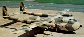
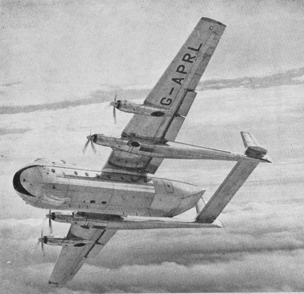
The series 100 led to the military Armstrong-Whitworth (later WhitworthGloster and Hawker-Siddeley) AW660 Argosy derived from the civil AW650, major design changes involving a “beaver tail” for air para-dropping, fixed nose doors, heavier and strengthened floor, Smith’s military flight system, Ekco weather radar-the scanner housing providing the characteristic bump on the nose and other internal equipment changes. Twenty aircraft (XN814-821, XN847-858) were ordered in January 1959 to replace the last of the Valettas, and a manufacturer’s prototype, G-APRL, was first flown on July 28, 1960, with some of the military modifications including the beaver tail doors. Follow-on production orders were placed for a further 36 aircraft (XP408-413, XP437-450, XR105-109, XR133-143), while the first RAF Argosy C1 (XN814) was flown for the first time on March 4, 1961. Together with the second aircraft it soon passed to the A&AEE at Boscombe Down for service trials prior to entry into service.
AW.660 prototype G-APRL
The variety of roles adopted by the Argosy are very wide-it can carry 54 fully-equipped paratroops (with two despatchers and one additional loadmaster); or two Ferret scout cars/ Land Rovers plus 20 troops in the air-transport role; or 64 passengers (with two air quartermasters); or 48 stretcher patients (with four attendants and two AQMs) for casevac. As a tactical support aircraft it can deliver nine x one ton containers or two medium-stressed platforms (12 0001b each). In the photographic role F-117B cameras can be installed, and for air-sea rescue Lindholme containers and flares are carried.
In the mid-1960s the first four operational squadrons (105, 114, 215 and 267) were active in the Far East, Gulf and European theatres.
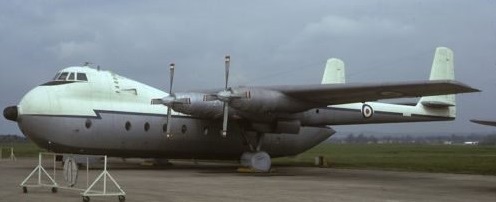
RAF Argosy XP409
An early attempt to offset the problems of short range was tried with XN819 early in 1962 when in-flight refuelling equipment was fitted. However, after trials at the A&AEE Boscombe Down, it was decided not to proceed with the modification programme. In the internal-security fit in 1963 XN814 was modified to accommodate external bomb racks (for 14 bombs) on each side of the lower fuselage; the nose window was equipped as a bomb aimer’s position. After successful trials with the “Argi-bomber” the aircraft used in Aden and the Far East were given this modification. There is no evidence that they were operationally used in this offensive role. The C and E Mk.1 aircraft had higher gross weights and more powerful engines than the 222. Fifty six were used by the RAF. With the delivery to the RAF of the Hercules it was announced in 1968 that the Argosy would be withdrawn from tactical transport duties by 1970. However the fuel tank corrosion problems encountered by the Hercules and the subsequent withdrawal of aircraft for modification meant that this target date could not be reached. The 660 had the ‘Shackleton Wing’ and had ‘clam-shell’ doors at the rear of the fuselage to allow air-dropping of stores. Unlike the civil 650, the nose was fixed. The early versions of the civil AW 650 also had the ‘safe life’ Shackleton wing. It was main spar failure that curtailed the fatigue life of the AW 650/660 aircraft. However later versions known as AW 650 200 were manufactured with a ‘fail safe’ wing of much more modern structural philosophy. The series 200 can be recognised as it is fitted with large wing fences. The 222 model was designed to the specifications of British European Airways, and began service in 1965. The 200 Series featured a redesigned box-spar increasing the MAUW and fuel capacity. Only 17 civilian Argoseys were built.
Argosy series 100 Engines: 4 x Rolls-Royce Dart 526 turbo-prop, 1506kW Take-off weight: 39916 kg / 88000 lb Empty weight: 20865 kg / 46000 lb Max payload: 28,000 lbs. Wingspan: 35.05 m / 114 ft 12 in Length: 26.44 m / 86 ft 9 in Height: 8.23 m / 27 ft 0 in Wing area: 15.45 sq.m / 166.30 sq ft Cruise speed: 451 km/h / 280 mph Ceiling: 6100 m / 20000 ft Range: 3219 km / 2000 miles Crew: 2-3 Passengers: 84
AW650-222 Cruise: 240 kts. No built: 7. Max payload: 31,000 lbs. MAUW: 93,000 lbs. Max range: 1600 nm. Approach speed: 108 kts.
Hawker Siddeley / Armstrong Whitworth AW 650 Argosy C Heavy transport aircraft, United Kingdom, 1961 Length: 89.173 ft / 27.18 m Wingspan : 114.993 ft / 35.05 m Max take off weight : 103017.6 lb / 46720.0 kg Max. speed : 233 kts / 431 km/h Service ceiling : 20013 ft / 6100 m Range : 300 nm / 555 km Engine : 4 x RollsRoyce Dart RDa 8 Mk 101, 2680 shp Crew : 3+69
Argosy C1 Engines: 4 x Rolls-Royce Dart RDa8 Mk102 turboprops, 2210 shp (dry) or 2470 shp (with water-methanol injection). MAUW: 97 000 lb. Cruise: 220kt @ 10000-20000ft. Max payload / range: 24600 lb over 180 nm. Max range/payload: 1700nm with 3500 lb. Radius of action/payload: 750nm with 5000 lb.
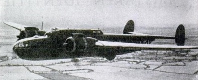
With a possible shortage of light alloys Air Ministry Specification B.9/38 for a twin engined medium bomber, was issued. This required that the aircraft was to be of simple construction, using materials other than light alloy wherever possible. AWA’s chief designer, John Lloyd, and his team were able to submit the initial proposals for their project, the AW.41, to the Air Ministry in February 1938. These initial proposals were for a mid wing monoplane of 61ft 8in span powered by two Rolls Royce Merlin engines and capable of carrying the normal bomb load of 1,500 lb for a range of 1,500 miles cruising at 320 mph at 20,000ft. The sole defensive armament consisted of a four gun power operated turret in the tail. From the outset the AW.41 was to have a retractable tricycle undercarriage. The construction of the airframe was to have been almost exclusively of wood and steel. The project was changed to meet Specifica¬tion B.18/38 for a twin engined reconnaissance bomber. The design study to meet B.18/38, although using the same type of construction, was very different to the original concept. The wing span was increased to 67ft and the Rolls Royce Merlins were replaced by Bristol Hercules XI radial engines driving three bladed de Havilland constant speed hydromatic airscrews.
On August 18, 1938, Contract 816726/38 was placed with AWA for the manu¬facture of two prototypes. Construction of the two prototypes was transferred to AWA’s factory at Hamble, and it was provisionally planned that the ensuing production would he undertaken at the new “shadow” factory being built at Yeadon, near Leeds. The plan for Yeadon was abandoned and in November 1939, production contract No B40671/39 for 198 aircraft was placed with Gloster Aircraft at Brockworth. A second contract, No B53250/39 for a further 800 aircraft, was placed with Gloster on January 30, 1940. Shortly after this the Hawker Siddeley Group formed a new com¬pany at Brockworth, A. W. Hawkesley Ltd, to be responsible for the assembly of the AW.41, which by then had been named the Albemarle.
The first prototype, P1360, com¬menced taxiing trials at Hamble on March 18, 1940, and AWA’s chief test pilot, F1t Lt C. K. Turner Hughes, continued the trials of P1360 on March 20, when, after satisfactorily completing the taxiing tests, he carried out a series of straights before taking P1360 off on its maiden flight.
Retraction of the undercarriage was carried out for the first time during the second flight on April 5. The company’s flight trials showed take off performance to be unsatisfactory and in July and August 1940, P1360 was grounded while the wings were modified, increasing the span by 10ft to 77ft. In September an A&AEE crew from Boscombe Down started the official performance and handling trials. During a flight on September 30 the pilot became lost and was compelled to make a forced landing in a small field. This was successfully accomplished with only minor damage to the air¬craft. October was to see further modifica¬tions to P1360, when the areas of the fins and rudders were increased. On November 16 the machine was delivered to the A&AEE at Boscombe Down for continuation of its official trials. It was during a flight from Boscombe Down on February 4, 1941, that a portion of plywood upper skin broke away from the port mainplane. The noise and effect of this led the pilot to believe that the aircraft was having engine trouble, so he immediately shut down the port engine. As a result the aircraft broke away into a spin from which the pilot was unable to recover. He ordered his two observers to abandon the aircraft, and the first cleared the aircraft safely, but the “D” ring of the other’s parachute caught in the fuselage, the observer finding that he was suspended by his harness from the fuselage. The parachute released and developed over the tailplane, acting in an anti spin role and enabling the pilot to regain control. Unaware of the drama being enacted behind him, the pilot found that he could control the aircraft if he did not allow the speed to fall below 30 or 40kt above stalling speed. With this knowledge the pilot decided to make a wheels up landing, still unaware that his observer was suspended below the fuselage. Just prior to landing, and when he was some 6 to 8ft above the ground, the observer released himself and fell to the ground. Although seriously injured, he survived, the pilot completed his wheels up landing with only minor injuries to himself, although the aircraft was totally destroyed in the ensuing fire. The second prototype, P1361, first flew on April 20, 1941, continued the flight test programme. This machine also had the 77ft span wing, and was the only Albemarle to be fitted with the ventral power operated turret. Production problems were caused by over 1,000 sub-contractors who lacked aircraft experi¬ence but were to manufacture all the details and sub assemblies required for the Albemarles. The technical problems with the prototype, particularly the increased wing span, required many of the jigs to be rebuilt. Only two Albemarles, the prototypes, had flown by June 1941, the first 200 were not completed until March 1943, and production ceased with the completion of the 602nd Albemarle in March 1945. Although contracts were placed for 1,000 Albemarles, this quantity was reduced to 602, including the two prototypes, in June 1943, when it was decided that the facilities at Brockworth were required for Meteor production. In 1941 the Albemarle programme was investigated by a Select Com¬mittee on National Expenditure, chaired by Sir John Wardlow Milne. The Committee issued its report on August 20, 1941, and it concluded that the Albemarle was not value for money, calling for immediate and urgent reconsideration of the programme.” It is interesting to note that an Albemarle airframe, less engines and equipment, cost £24,950, compared with £19,159 for a Lancaster. The Prime Minister, Winston Churchill, was concerned about the Committee’s findings, and on August 26, 1941, asked the Secretary of State for Air to provide him with the current views and intentions of the departments involved with the Albemarle. Explanations from the Air Staff and the Ministry of Aircraft Production, defending the Albernarle and their decisions made in regard to it, did not appear to satisfy Churchill, and it apparently took a letter from Lord Beaverbrook on October 12 to finally reassure him. In his letter, Beaverbrook advised that the Alhemarle would be useful for short-range work, and would supplement the Wellingtons in attacks on invasion ports, for bombing in France and for bombing in the event of an invasion. He also explained that the tooling was practically complete at a cost of over £1,500,000, and that more than 75 per cent of the raw materials had been delivered and 50 per cent of the details manufactured. Deliveries of production aircraft from Brockworth commenced in September 1941, although it was not until June 1942 that monthly deliveries exceeded double figures, with 14 air¬craft being delivered. The first 32 production aircraft were completed as B.Mk.1’s, but the delays had already rendered the Albemarle obsolete as a bomber, and consequently no further aircraft were completed as such, all subsequent machines being produced as glider tugs or special transports. Projects to cater for any shortage of Hercules engines that may have arisen were the Mk.III with Merlins and the Mk.IV with Wright GR2600 Double Cyclone engines. Cyclones were installed in Mk.I P1406, and a single GTIV, V1760, was completed. The Merlin installation was not proceeded with.
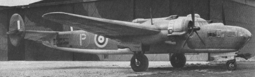
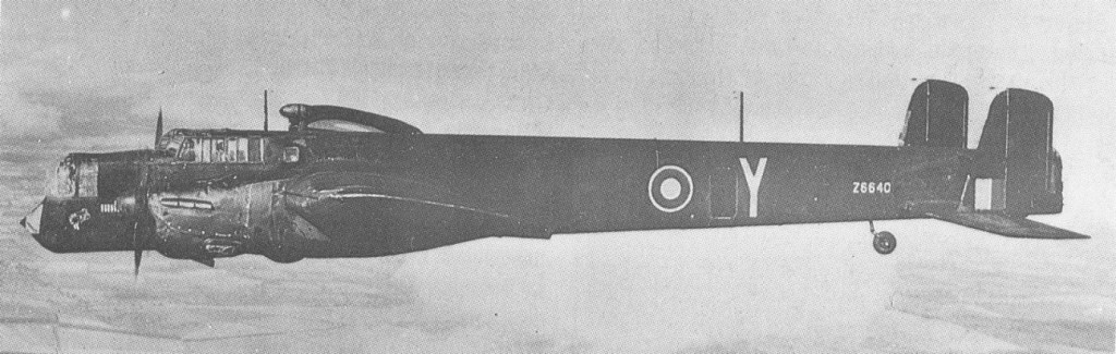
Albemarle I V1599 was experimentally fitted with a long travel undercarriage by AWA during 1943. This was to enable it to fly directly on to the ground without the necessity of a flare out before touch down. Flight testing commenced on November 8, 1943, but it did not prove to be a complete success because the undercarriage oleos failed to compress sufficiently under drag load during flight. 600 Albemarles were produced between 1941 and 1943. It was widely used as a glider tug, although it suffered from overheating through sustained high power at low airspeed. There were many GT (general transport) and ST (special transport) versions, some equipped with four gun dorsal turrets (a few had a two gun belly turret) or twin manually aimed dorsal guns. Most could carry freight, paratroops or special equipment. The first ST.I and GT.I entered RAF service in mid-1942 and early 1943 respectively, and subsequent versions brought the total number of Albemarles built to 600. One batch was supplied to the Soviet Union.
The Albemarle took part in the invasion of Sicily to which they were used to tow support gliders into action. Additionally, the aircraft took part in the D-Day invasion landings of June 1944 (again as glider tugs) and served with airborne elements during the airdrops over Arnhem campaign to end the war before Christmas.
Armstrong Whitworth AW 41 Albemarle Engine: 2 x Bristol Hercules XI, 1568 hp Length: 59 ft 11 in / 18.26 m Height: 15 ft 7 in / 4.75 m Wingspan : 77.00 ft / 23.47 m Wing area : 803.533 sqft / 74.65 sqm Max take off weight : 22603.5 lb / 10251.0 kg Max. speed : 230 kts / 426 km/h Cruising speed : 148 kts / 274 km/h Service ceiling : 17995 ft / 5485 m Wing load : 28.09 lb/sq.ft / 137.00 kg/sq.m Range : 1130 nm / 2092 km Crew : 4 Armament: 2x cal.303 MG Vickers “K” (7,7mm)
Air Ministry Specification B.3/34 called for a bomber that could carry a bomb load of 2000 lbs for 1250 miles at a height of 15,000 feet at a maximum speed of 225 mph. As the RAF’s existing hangar doors were little more than 100 feet wide, putting a firm limit on the aircraft’s wingspan which was only 84 feet but with a wide chord and thick wing section. There were four contenders to build to specification B.3/34 with Armstrong Whitworth becoming the chosen company. The A.W.38 (which was later named Whitley after the airfield and works near Coventry) contained design features that had previously been tested by the company in the A.W.23 transport/bomber. The new light alloy wing construction consisting of a basic torsion box of web corrugated vertically, and spanwise gave it strength aided by an internal bracing of steel struts.
The prototype Whitley, K4856, was first flown on March 17, 1936. With increasing urgency for the RAF to re-equip and after an original order for 80 aircraft, a second order for 240 Whitleys was signed on 13 May 1936, two months after the prototype’s first flight.
The second prototype and 34 Mk I production aircraft which followed were all powered by two 592.5kW Armstrong Siddeley Tiger IX radial engines. The first production Whitley, K7183, was delivered in the early months of 1937, with the second aircraft, K7184, being flown direct on March 9 from Baginton to No 10 Squadron, which was then equipped with Handley Page Heyfords.
The original design had no wing flaps but later flaps – with a maximum deflection of 60o – were incorporated. With a wing area of over 1,200 square feet and a high angle of attack, the type had superb lift, but the original power plants – 795 hp Armstrong Siddeley Tiger IX air cooled radials – left the early Marks of Whitley under-powered. Half way through the first production batch, after 34 aircraft had been completed, the Whitley 1 was superseded by the Mk II version in which the 795 hp Armstrong Siddeley Tiger IX engines were replaced by 845 hp Tiger VIII engines incorporating a two speed supercharger.
The Mk III would appear shortly after the initial batch, introducing a Nash & Thompson ventral gun position that was retractable.
The need for still more performance and greater reliability resulted in a decision to adopt 1,745 hp Rolls Royce Merlin Xs for the Mk IV. The first Merlin powered example flew on February 11, 1938. A subvariant of the Mk IV would appear with a newly-configured powered tail turret housing quad 7.7mm machine guns.
The first Mark V came off the line on 28 August 1939 and production of this Mark lasted four years and accounted for 90 percent of the total number of type built; over 2,000 in all.
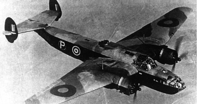
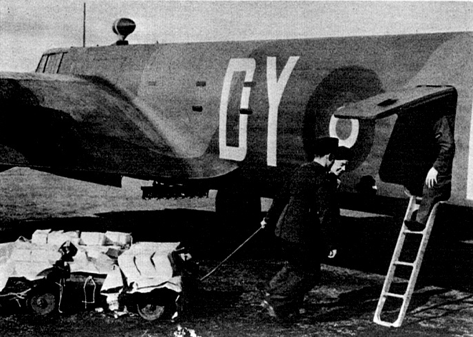
Whitley V of 78 Sqn, RAF
At the outbreak of the Second World War almost all of the Whitley Is and IIs had been withdrawn from operational status as heavy bombers, although seven squadrons (Nos 10, 51, 58, 77, 78, 97 and 102) were equipped with the Mk IIIs, IVs or Vs.
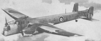
102 Sqn Whitley leaflet dropping
After the introduction of four engined bombers such as the Halifax, Stirling and Lancaster during 1940 41 Whitleys continued bombing operations over Germany until April 1942 the last raid taking place on April 29 30 to Ostend.
At the end of the war the type was still in service for training and other miscellaneous duties. The Whitley was responsible for the first bombing raid on Germany, in May 1940; the first bombing raid on Italy, in June 1940; and the first paratroop operation over Southern Italy, in February 1941. The last Whitley built, LA951, was retained by the Armstrong Whitworth company on its completion in 1943. It was used for general test and experimental flying, one of its main tasks being to act as a tug for the A.W.52G glider. Four years later, in March 1949, LA951 was withdrawn from service and dismantled.
Whitley Mk I Engines: 2 x Armstrong Siddeley Tiger IX, 795 hp / 592.5kW
Whitley Mk II Engines: 2 x Armstrong Siddeley Tiger VIII, 845 hp
Whitley III Engines: 2 x Armstrong Siddeley Tiger VIII, 920 hp. Max speed: 215 mph Cruise speed: 177 mph Range: 1300 mi
Whitley IV Engines: 2 x Rolls-Royce Merlin, 1030 hp Wingspan: 84 ft 0 in Length: 70 ft 6 in Max speed: 245 mph Cruise: 215 mph Normal range: 1250 mi Max range: 1800 mi
Whitley V Engines: 2 x Rolls-Royce Merlin X, 840kW / 1,145hp Wingspan: 25.6 m / 84 ft 0 in Length: 21.5 m / 72 ft 6 in Height: 4.6 m / 15 ft 1 in Wing area: 114.4 sq.m / 1231.39 sq ft Maximum Take-off weight: 12800 kg / 28219 lb Empty weight: 8770 kg / 19335 lb Wing load : 29.52 lb/sq.ft / 144.0 kg/sq.m Fuel cap: 837 Imp.gal. Max. speed: 357 km/h / 222 mph Cruise speed: 297 km/h / 185 mph Rate-of-Climb: 938ft/min (286m/min) Op. Ceiling: 5360 m / 17600 ft Service ceiling: 26,000 ft / 7,925m Range w/max.fuel: 2600 km / 1616 miles Range w/max.payload: 760 km / 472 miles Armament: 1 x 7.7mm machine gun in nose turret 4 x 7.7mm machine guns in tail turret Bombload: 7,000lb / 3150kg Crew: 4-6
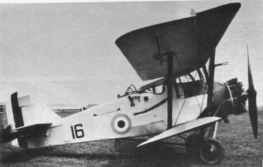
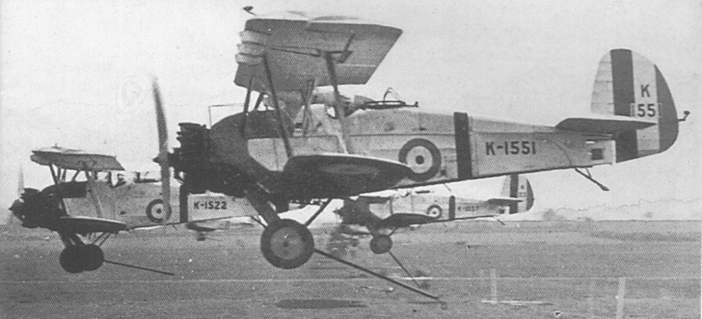
The Armstrong Whitworth Atlas was designed to replace the de Havilland DH.9A biplane of 1918 as well as the Bristol Fighter of 1916 against the RAF requirements of Specification 20/25. The Atlas design was intended to replace both airframes as the primary RAF “army co-operation” (mission liaison) mount. The Atlas was attributed to an engineering team led by John Lloyd who headed up design at the Armstrong Whitworth Aircraft firm as its Chief Designer.
Armstrong Whitworth and Lloyd’s design team initially undertook the Atlas project as a private venture, the prototype first flying on May 10th, 1925. The RAF then accepted the prototype for evaluation against other aircraft and the two-seat Atlas biplane proved a sound design save for some noticeable “sideslipping”. The issue was resolved with the fitting of new metal wings that featured sweepback. However, the new wings degraded the quality of the aircraft’s in-flight handling – then deemed excellent – and now showcased poor stall characteristics as well. As such, automatic slats were added to the wings and sweep was increased to an extent and, in the case of aircraft for the RCAF, the addition of ailerons on the lower wings. This rectified the less-than-stellar handling characteristics caused by the wing change.
Design was highly conventional for the time. The aircraft mounted its engine in a forward compartment to power the propeller system. The steel tube fuselage (fabric covered) was rather rounded in shape, thicker forward and tapering off at the rear. The wings were of an unequal span, single-bay biplane assemblies made of metal sporting slight dihedral on each unit, moreso in the lower assembly. The pilot sat direct aft of the upper wing assembly in an open-air cockpit with his observer/gunner in an open-air cockpit aft of the pilot. The empennage was relatively conventional in design, featuring a rounded vertical tail fin with a pair of horizontal stabilizers. The undercarriage varied based on sortie need – either a pair of wheels were set in a fixed undercarriage for land-based assignment or a set of long-running pontoon floats could be installed for at-sea work. Either way, the empennage was supported by a simple tail skid made particularly suitable for the land-based model. A hook could be optionally fitted to the fuselage underside to make quick pick-ups of ground messages without having the aircraft be required to land.
Standard armament for the series centered around a pairing of machine guns. A .303in (7.7mm) Vickers type machine gun was in a fixed position set to fire forward. A .303 (7.7mm) Lewis machine gun was mounted on a “Scarff ring” in the rear cockpit for trainable fire against emerging enemy threats from the rear. The flexible Scarff ring was developed in World War 1 by Britain Warrant Officer (Gunner) F.W. Scarff to address the armament needs of a rear gunner faced with the prospect of fighting the enemy from multiple angles from his open-air cockpit. In addition to the machine guns, the Atlas could be fitted with 112lb bombs under the wing elements.
Production of the Atlas began soon after with the aircraft formally introduced for service with the British Royal Air Force in 1927, an initial production batch numbering 37 aircraft. The Atlas entered service with 13 Squadron and 26 Squadron immediately and was eventually fielded with the overseas 208 Squadron out of Heliopolis, Egypt in 1930. It served in the mission liaison role – as well as trainer and communications – up until she was retired in 1935.
The initial production model became the Atlas I and some 271 examples were delivered to the RAF. Production lasted from 1927 to 1933 to which 478 were ultimately produced. 175 were dual-control advanced trainers. The Atlas Trainer served as a dual-control mount in the training of future Atlas pilots.
These aircraft were to remain in service until 1934 in the army cooperation role, and as advanced trainers and communications aircraft into 1935.
Beyond British use, the Atlas was in the inventories of Canada, Egypt and Japan. The Atlas was eventually superseded by the Hawker Audax, based on the Hawker Hart biplane, and its trainer derivatives were themselves replaced by the Hawker Hart Trainer.
The Atlas II soon appeared as an improved Atlas model with more output from its Armstrong Siddeley Panther IIA engine of 525 horsepower/399kW, radio, message pick-up hook and cameras. However, the RAF elected to go with the competing Audax design and 15 of this model were delivered to the Chinese Air Force. Ajax represented Atlas I models with slight variations and only 4 were ever built for the RAF. Aries was a proposed and improved Atlas I model with slightly larger surfaces and overall dimensions while also being made easier to maintain in the field. However, only one was ever completed. The EAF Atlas was an export product for the Greek Air Force (Hellenic Air Force) that primarily differed in its selected engine, propeller and wing assemblies. At least 10 of this model were locally built by EAF (State Aircraft Factory) in Greece after 1931.
The last Armstrong Siddeley Atlas in RAF service was fielded by 208 Squadron, which replaced their aircraft with the newer Hawker Audax in 1935. Privately-held Atlas aircraft operated until 1938.
Atlas Mk I Engine: 1 x Armstrong Siddeley Jaguar IVC, 450hp / 298kW. Length: 28 ft 6.6 in (8.68m) Wing span: 39 ft 6.6 in (12.04m) Height: 10 ft 6 in (3.20m) Empty Weight: 2,557 lbs (1,160kg) Maximum Take-Off Weight: 4,028 lbs (1,827kg) Endurance: 3.5 hr Maximum Speed: 142mph (229kmh; 124kts) Maximum Range: 400miles (644km) Service Ceiling: 16,798ft (5,120m; 3.2miles) Armament: 1 x 7.62mm Vickers mg, 1 x 7.62mm Lewis mg position Up to 4 x 50kg bombs underwing Crew: 2 Hardpoints: 4
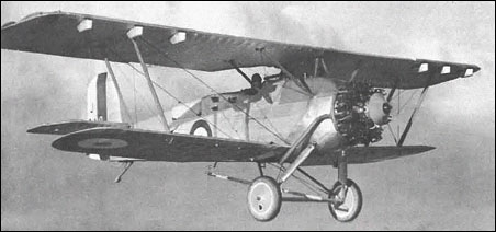
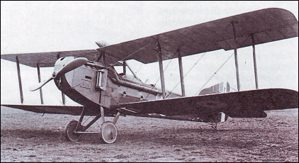
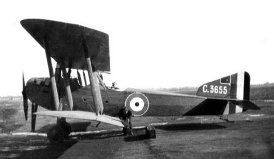
Designed by Frederik Koolhoven, the F.K.8 prototype first flew in May 1916, and was similar to its predecessor, the F.K.3 and intended to supersede the capabilities of the FK.3.
The standard production versions were powered by a 120 hp Beardmore engine and in the original form had an angular engine cowling and radiators which met in an inverted Vee in front of the top wing. After a time production aircraft were delivered with a more rounded cowling carrying a small box-like radiator on each side.
Early models had a Vee-skid in front of their wheels.
Later machines with a 160 hp Beardmore. All were fitted with a form of dual control so that the rear cockpit observer could partially fly the machine if his pilot was incapacitated.
Armament consisted of a single forward-firing fixed 7.62mm Vickers machine gun and a single 7.62mm trainable Lewis-type in the rear cockpit position. Provisions for bombs were also a part of the arsenal for the FK.8.
F.K.8
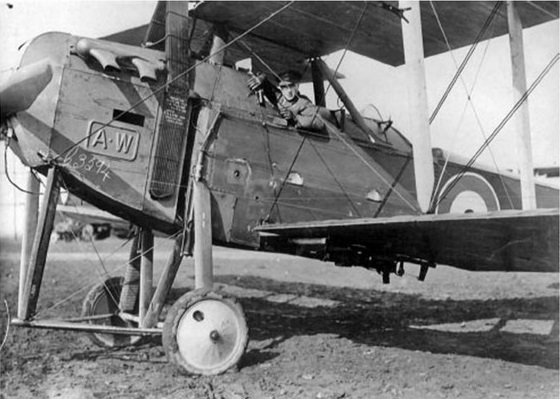
The first RFC unit to receive F.K.8s was 35 Squadron, which flew fully equipped to France on January 24, 1917. Number 2 Squadron began to re-equip in April 1917; 10 Squadron in July; 8 Squadron in August, and 82 Squadron, fully equipped with the type, arrived in France in November 1917. In the Middle East zone of operations, 17 and 47 Squadrons in Macedonia, and 142 Squadron in Palestine were equipped with F.K.8s by 1918, and continued to operate them until the end of the war. In England, several home defence units were partly equipped with the F.K.8, and one belonging to 50 Squadron was responsible for shooting down a Gotha bomber on July 7, 1917.
The F.K.8 first came into prominence during the German spring offensive of March 1918, being used primarily in a tactical low-level bombing and strafing role against German infantry.
F.K.8
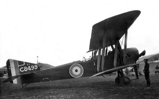
At least 1596 machines were built and delivered for service use. By October 31, 1918, a total of 694 F.K.8s were still on RAF charge, but at the end of 1919 few examples remained. Eight found their way onto the Civil Register, and two went to Australia where they helped to pioneer air travel from late 1922 onwards.
Armstrong Whitworth F.K.8 Engine: 1 x 120hp Beardmore Wingspan: 13.26 m / 43 ft 6 in Length: 9.58 m / 31 ft 5 in Height: 3.33 m / 10 ft 11 in Wing area: 540 sq.ft Armament: 1 x 7.62mm Vickers mg, 1 x 7.62mm Lewis mg
Armstrong Whitworth F.K.8 Engine: 1 x 160hp Beardmore Wingspan: 13.26 m / 43 ft 6 in Length: 9.58 m / 31 ft 5 in Height: 3.33 m / 10 ft 11 in Wing area: 540 sq.ft Max take-off weight: 1275 kg / 2811 lb Empty Weight: 1,918 lbs (870kg) Fuel capacity: 47.5 Imp.Gal Max. speed: 153 km/h / 95 mph / 83kt Service ceiling: 3690 m / 12100 ft Endurance: 3 hr Armament: 1 x 7.62mm Vickers mg, 1 x 7.62mm Lewis mg Crew: 2 Hardpoints: 4