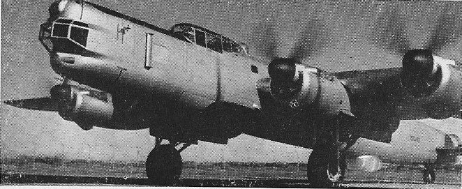
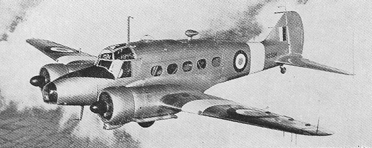
Beginning as an A. V. Roe project in 1958, the original Type 748 was planned as a 20-seat short/medium-range feeder airliner. When no interest was shown in the design, it was scaled up in size and the Hawker Siddeley Group, of which Avro was a component company, decided to put the aircraft into production.
The first flight of the prototype took place at Woodford on 24 June 1960. The first production aircraft, capable of seating a maximum of 48 passengers, was designated Avro 748 Series 1. It first flew on 31 August 1961, powered by two 1298kW Rolls-Royce Dart 514 turboprops.
This aircraft has a takeoff run of only 2,750 feet, for STOL performance it has a long-span wing, mounted low, with Fowler flaps driven by an electric actuator. The Rolls-Royce Dart turboprops, mounted with their jet pipes above the wings, are rated at about 2,280 hp, though some military versions have 3,200-hp Darts. Most civil versions of the HS 748 seat 40 to 58 passengers and some are equipped for freight or passenger/freight operations.
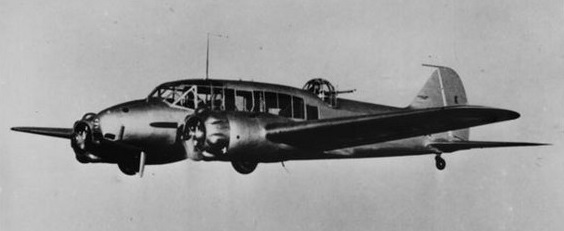
Redesignated HS.748 in 1963, later versions included the Series 2 and Series 2A (1967) civil transports; Andover CC.Mk 1 and CC.Mk 2 for the RAF, the CC.Mk 2 being two specially equipped examples for The Queen’s Flight; the Coastguarder variant was also developed, optimised for maritime patrol, flying in 1977.
Six Andovers were delivered to the RAF, two for Queen’s Flight, and four for special passenger service. Prince Phillip Duke of Edinburgh, after completing transition training, used Queen’s Andover CC Mk.2 during his tour of Mexico and Caribbean in October and November 1964.
Hawker Siddeley Andover C.1
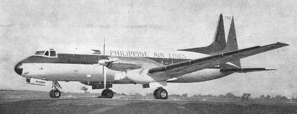
1st of six HS.748 for Philippine Air Lines, handed over at Woodford, 29 September 1967
The 748-2B incorporated a 2000 lb increase in payload, increased span, more powerful engines, and a number of cockpit refinements, flew in June 1979. A production version of the twin-turboprop transport is the Super 748. In its Military Transport form the 748 has a large rear freight door, strengthened floor, and optional military overload take-off and landing weights giving improved payload/range capabilities.
Andover NZ7626
Outwardly, the 748 is similar to the 780 Andover aircraft which differ mainly in having more powerful engines (and reverse pitch propellors), a rear loading ramp, and a kneeling undercarriage. Only 31 Andovers were built, along with six of the Andover CC.2 version of the civil 748. Although developed from the basic Hawker Siddeley 748 and retaining it’s exterior looks, with the exception of the revised tail and straight-in loading ramp, the Andover does have only 20 per cent commonality with the 748. The Andover’s “kneeling” undercarriage allows the aircraft’s fuselage to be lowered to allow easier loading and unloading. The STOL performance for a 42,000 lbs take off, the Andover requires 1,300 ft (to 50 ft), while 1,340 ft is needed for a short field landing (from 50 ft) at 40,000 lbs auw. Reverse-thrust propellors assists the short field performance. Production of all versions, including 79 assembled in India by Hindustan Aircraft from parts manufactured in both countries, totaled 380 aircraft.
HS748-2A Engines: 2 x Rolls-Royce Dart, 2280 shp. Wing span: 98 ft 6 in (15.24 m). Length: 67 ft 0 in (20.42 m). Height: 24 ft 10 in (3.51 m). Max TO wt: 44,495 lb (20182 kg). Max level speed: 278 mph (448 kph).
BAE 748-2B Engines: 2 x Rolls-Royce Dart 7 Mk.535-2, 1,835 shp. Props: Dowty-Rotol 4-blade, 144-in. Seats: 48/50. Length: 67 ft. Height: 24.8 ft. Wingspan: 102.5 ft. Wing area: 829 sq.ft. Wing aspect ratio: 12.7. Maximum ramp weight: 46,700 lbs. Maximum takeoff weight: 46,500 lbs. Standard empty weight: 26,650 lbs. Maximum useful load: 20,050 lbs. Maximum landing weight: 43,000 lbs. Wing loading: 56.1 lbs/sq.ft. Power loading: 12.7 lbs/hp. Maximum usable fuel: 11,200 lbs. Best rate of climb: 1470 fpm. Service ceiling: 25,000 ft. Max pressurisation differential: 5.5 psi. 8000 ft cabin alt @: 25,000 ft. Maximum single-engine rate of climb: 359 fpm. Single-engine ceiling: 10,700 ft. Maximum speed: 250 kts. Normal cruise @ 25,000ft: 230 kts. Fuel flow @ normal cruise: 1257 pph. Endurance at normal cruise: 8.4 hrs: Stalling speed clean: 95 kts. Stalling speed gear/flaps down: 71 kts. Turbulent-air penetration speed: 155 kts.
HS 748 series 2B Engines: 2 x Rolls-Royce Dart Mk 555, 1700kW Take-off weight: 23133 kg / 51000 lb Empty weight: 11644 kg / 25671 lb Wingspan: 31.23 m / 102 ft 6 in Length: 20.42 m / 66 ft 12 in Height: 7.57 m / 24 ft 10 in Wing area: 77.0 sq.m / 828.82 sq ft Cruise speed: 452 km/h / 281 mph Ceiling: 7620 m / 25000 ft Range w/max.payload: 1307 km / 812 miles Crew: 2-3 Passengers: 52
748 Military Engine: 2 x R-R Dart turboprop, 3400 kW. Span: 31.2 m. Length: 20.4 m. Wing area: 77 sq.m. Empty wt: 11,700 kg. MTOW: 23,100 kg. Payload: 5800 kg. Cruise speed: 455 kph. Initial ROC: 430 m / min. Ceiling: 7600 m. T/O run: 1082 m. Ldg run: 387 m. Fuel internal: 6550 lt. Range/payload: 1865 km with 5800 kg. Capacity: 60 pax.
748MF Andover C.1 Engines: 2 x RR Dart 12 Mk 201C, 3,000 shp. MTOW: 50,000 lbs. Fuel cap: 1,440 Imp gallons, + 860 gallons in an integral centre-wing tank. Range: 1,020 nm (1,800 nm with 860 Imp aux). Pax cap: 57 passengers (at 30” pitch). Cruise alt: 20,000 ft. Max speed: 302 mph @ 15,000 ft. Service ceiling: 23,800 ft. Maximum payload: 14,750 lbs. Take off distance mauw: 3810 ft. Landing ground roll max ldg wt (47,600 lbs): 2490 ft.
HS.780 C.1 Engines: 2 x Rolls-Royce Dart 12 Mk.201, 3425 shp. Max payload: 6270 kg.
Hawker Siddeley Andover C Mk 1 Engine: 2 x Rolls Royce Dart R.Da 12 Mk. 210 C, 2929 shp Length: 77.92 ft / 23.75 m Height: 30.085 ft / 9.17 m Wingspan: 98.261 ft / 29.95 m Max. speed: 262 kts / 485 km/h Service ceiling: 24016 ft / 7320 m Range: 1031 nm / 1909 km Crew: 3+44
748-2A Andover CC2 Engines: 2 x RR RDa7 Dart 152, 2280 shp. TBO: 1600 hr. Max cruise: 245 mph. Econ cruise: 243 mph. Stall: 82 mph. Fuel cap: 11628 lb. Fuel flow max cruise: 1850 pph. Fuel flow econ cruise: 1400 pph. Service ceiling: 23,000 ft. SE service ceiling: 13,000 ft. ROC: 1300 fpm. SE ROC: 750 fpm. Min balanced field length: 4050 ft. Payload with full fuel: 8790 lb. Max range: 1828 mile. High speed range: 1068 mile. Max payload: 16,773 lb. Range with max payload: 761 mile. Pressurisation differential: 5.5 lb. Seats: 47. Gross wt: 46,500 lb. Empty wt: 29,727 lb. Useful load: 16,773 lb.
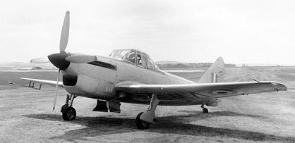
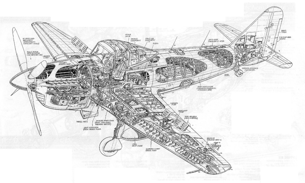
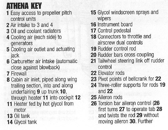
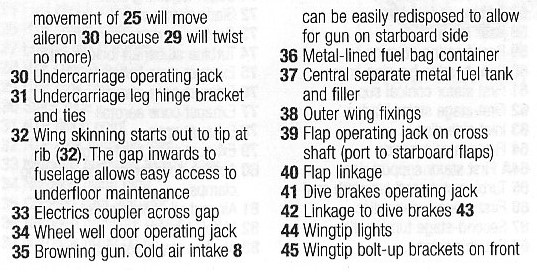
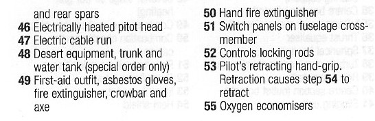
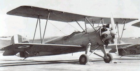
The Athena was a single engine side-by-side two seat trainer with a tail wheel undercarriage. designed to Specification T.7/45 for a three-seat turbo-prop advanced trainer.
Two turbo-prop versions were developed, the Athena T.1 with a 1135 eshp A.S. Mambe A.S.Ma.1, and the Athena T.1A with a 1125 eshp Rolls-Royce Dart R.Da.1
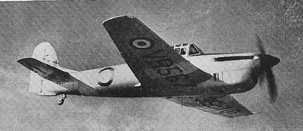
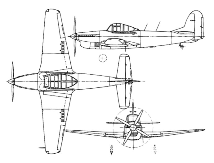
Athena T.2
The design was then modified to meet specification T.14/47, and seventeen pre-production Athena T.2s were built, powered by the 1280 hp / 954kW Rolls-Royce Merlin 35. First flown in 1948, the Athena T.2 advanced trainer was in pro¬duction by 1950. These eventually went to the RAF Flying College, Manby, as gunnery trainers.
Athena T.Mk 2 Engine: 1 x Rolls-Royce Merlin 35, 1280 hp / 954kW Take-off weight: 4256 kg / 9383 lb Empty weight: 2966 kg / 6539 lb Wingspan: 12.19 m / 40 ft 0 in Length: 11.37 m / 37 ft 4 in Height: 3.94 m / 13 ft 11 in Wing area: 25.08 sq.m / 269.96 sq ft Max. speed: 472 km/h / 293 mph Cruise speed: 359 km/h / 223 mph Ceiling: 8840 m / 29000 ft Range: 885 km / 550 miles
The original Avro 698 Vulcan B1 prototype was developed to Air Ministry Specification B.35/46, issued on 1 January 1947 for Britain to have nuclear bombing capability. The initial design was laid down in 1948 by Roy Chadwick, the technical director of Avro (A.V. Roe and Co. Ltd), and was preceded by the 707 series.
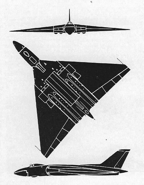
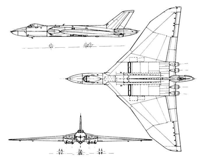
This design featured vertical tail surfaces at the extreme wingtips as opposed to a traditional tail section, offering up a great deal of surface area for improved payload, fuel load and maneuverability. The lack of a true tail section meant that, in some ways, the design was in fact a flying wing. The cockpit was positioned well forward on the fuselage, ahead of the wings and engines, and featured four engines in a staggered internal placement- two engines to a wing. The engines were to be fed by a single large rounded intake. The massive expanse of the wings would have also provided maximum space for internal armament in the form of bomb bays mounted outboard of the dual engine arrangements. Avro designated the new design Type 698 and received the British Air Ministry contract in December of 1947. Along with the Avro design, approval of the Valiant and Victor were also granted, essentially beginning the formation of the V-bomber triangle.
The initial Air Ministry contract called for several forms to be built including two prototypes. Along with this commitment included the construction and delivery of several flight demonstrators. The demonstrators, designated as Type 707, proved an important part of early development of the Vulcan. These development models eventually gave rise to the Type 698 prototype.
Flying for the first time on 30 August 1952, the Avro 698 prototype, VX770, had 6,500 lb.s.t. RA3 Avons, subsequent power-plants included the 8,000 lb.s.t. Sapphire, the 10,000 lb.s.t. Olympus 101s and the 20,000 lb.s.t. Olympus 301s. All four engines could be started, flight instruments aligned and powered flying controls run-up within 20 seconds. It had main qears with a total of 16 tyres, and a five seat crew compartment. A single large weapon bay was provided. The first prototype was later lost in a fatal air show accident in September of 1958.
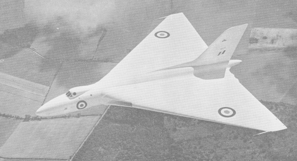
A second prototype powered by four 10,000lb Bristol Siddeley Olympus 101 – with a slightly longer fuselage to eliminate the need for shortening the nose-wheel leg during retraction – made its first flight on 3 September 1953. Both prototypes featured a delta wing with 52 degree sweepback. The second prototype was later fitted with a “kinked” wing design that showcased differing degrees of sweepback separated into different sections of the wing leading edge. The second was later fitted with wings having a redesigned leading edge with compound sweepback and it made its first flight in this form on 5 October 1955.
Wellington, New Zealand 1959
The fuselage itself was streamlined highly, with the cockpit mounted behind a nose cone assembly and just before the wing root intakes and fuselage extending well forward of the wing roots and some distance aft of the wing trailing edge. Fuel was split between either wing and a central fuselage location, all monitored in-flight by a fuel management system. The bomb bay was centrally held in the fuselage and could be fitted with additional fuel for increased range.
The undercarriage consisted of two main landing gears (retracting forward outboard of the engines) and a nose gear positioned behind and underneath the wingroot intakes. Each main gear was fitted with an eight-wheel bogie and retracted forwards while the nose gear and its two wheels retracted backwards. The empennage featured a single large dorsal fin extending from about the midway portion of the fuselage, with the base of the fin extending vertically out from about the extreme end point of the engines. The tail cone housed a drag chute to improve the aircraft’s landing distance.
The Avro Vulcan provided accommodation for five standard crew personnel consisting of the pilot and copilot, a systems operator, a navigator and a radar operator along with additional seating for two more. The pilot and copilot had a view out of the front of the cockpit through a five panel windscreen with framing as well as circular windows to the sides allowing for viewing to the left and right. Ejection seats were afforded to the pilot and co-pilot only – not the entire crew – they would have to bail out.
All production Vulcans were fitted with wings having the revised leading-edge configuration and the first production version was the Vulcan B.1, which entered RAF service in Febru¬ary 1957, powered by Olympus Mk 101 or Olympus Mk 102 engines of 4990 kg (11,000 lb) thrust each. All of these engines were converted later to Olympus Mk 104 standard, up¬rated in stages to 6078 kg (13,400 lb) thrust.
Twenty-five such machines were ordered in 1952 and the first Vulcan squadron became operational in 1957 (this delay in years was caused by yet another fatal accident). B.Mk 1’s were similar to the two prototypes. Early production models were finished the straight delta wings but these were later revised to the kinked wing design. The Mk.1s equipped Nos 83, 101 and 617 Sqn by early 1960. Nos 83 and 101 Sqns were re-equipped with Vulcan 2sband their Mk.1s were taken over by 44 and 61 Sqns.
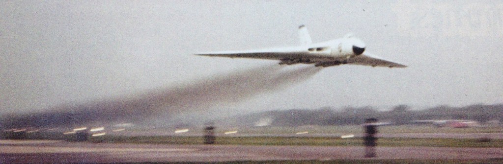
Farnborough Air Show – September 1958 – 83 Sqn RAF Vulcan B.1
Production models were fitted with an Olympus 101 series engine of 11,000lb thrust (each). This rating was progressively uprated until reaching the Olympus 104 series with 13,500lb thrust. A total of 45 Vulcan B.Mk 1 models were eventually delivered. Re-equipment of three Bomber Command squadrons of the RAF with this version was completed in 1960.
In the late 1950’s, the Vulcan B.Mk 1 had her countermeasures suite revised, becoming the Vulcan B.Mk 1A. Soviet defense technology advanced to the point that operation of the Vulcans in their originally intended mode was now in danger. As such, the aircraft was fitted with chaff dispensers, a tail warning radar (“Red Steer”), a radar warning receiver, and jammers. Twenty-eight B.Mk 1s were converted in this fashion with conversions taking place from 1959 into 1963. B.Mk1A’s and the future B.Mk 2 models were clearly discernable thanks to the addition of the ECM gear in the tail cone.
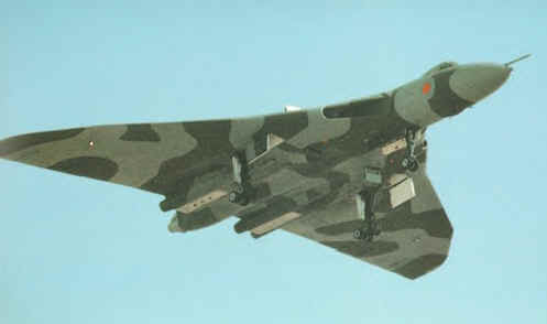
The Vulcan B.Mk 1 was followed by the Vulcan B.Mk 2 with development beginning in 1955. The system featured a revised and lengthened wing (increased from 99 feet to 111 feet), new Bristol Siddeley Olympus 201 series engines of 17,000lb thrust engines (later production models would feature the Olympus 301 at 22,000lb thrust), updated electrical system, in-flight refueling probe, a reinforced undercarriage (necessitated by the addition of the new engines), the countermeasures suite in the B.Mk 1A upgrade above and overall improvements to the aircrafts performance. First flight of the B.Mk 2 prototype occurred on August 19th, 1958 with deliveries beginning two years later and making up 89 total production examples. The increased performance offered by the Vulcan B2 made it ideal for modification to carry the Blue Steel nuclear stand-off bomb. This weapon allowed the aircraft to launch its attack from outside the immediate missile defences of a target and thereby extended the effectiveness of the Royal Air Force’s airborne deterrent.
This mark entered service in July 1960, and at first remained a high-altitude bomber. By 1961, Vulcan Mk.2s were in service with No.27, 83 and 10 Squadrons. By 1966 these had been withdrawn as the entire force had by that time switched to low level operations using conventional bombs, with a TFR (terrain following radar) on the nose.
Eight B.Mk 2 models were converted to Maritime Radar Reconnaissance platforms (B.Mk 2MRR)) and 6 more were modified as in-flight refueling tankers (K.Mk 2)).
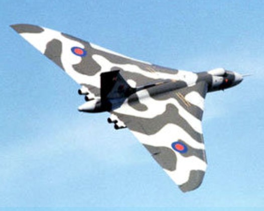
Four Vulcan SR.Mk. 2 reconnaissance aircraft served with No.27 Sqn, and the force was being run down when in April 1982 Argentine forces invaded the Falklands. Several aircraft were converted as tankers in a crash programme by British Aerospace, while others were urgently equipped with bombs, new navigation systems, flight refuelling probes, and underwing pylons for ALQ 101 ECM pods and Shrike anti radar missiles. They bombed Stanley airfield in round trips exceeding 12870km (8000 miles). The 1964 edition did Jane’s revealed that the Vulcan B2 could cruise at Mach 0.94 at 55,000 feet. Range hi/lo was 2,300 and 1,725 miles respectively. Vulcans served as engine test-beds for TSR-2 and Concorde. Production was completed in 1964 and a total of 134 were built at Avro’s Woodford, Cheshire plant, along with the two Type 698 prototypes. The Vulcan series of bombers saw limited use in combat aggression. Vulcan B.Mk 1 model bombers were sent as an intimidation factor during the Malayan Insurgency. Beyond that, they were used to showcase the types reach to the Soviet Union by conducting regular global flights to and fro. Operations with American forces and other NATO allies were a common occurrence. The only true combat actions including the Vulcan came in the 1982 Falklands War between invader Argentina and responder Britain. Vulcan B.Mk 2 bombers were used in small numbers during the conflict and succeeded in providing Britain with an intimidating force – though actual damage caused to enemy ground forces from Vulcans were minimal. Regardless, the presence of the Vulcan was no doubt on the minds of Argentine ground forces. After the war of 1982, the Vulcan’s career as a dedicated bomber was all but over. Several were converted as an interim measure to fulfill a tanker role gap while the Vickers VC10 airframes were being modified for the job. Six such Vulcan B.Mk 2 models were converted for the role and became the Vulcan K.Mk 2. These Vulcans lasted until 1984 as the VC10s came online.
The last Vulcan squadron was disbanded in March 1984.
On 18 October 2007 Vulcan B.2 XH558 flew from Bruntingthorpe in Leicestershire after a decade long restoration.
Avro Vulcan B Mk.I Engine: 4 x Bristol Olympus 101, 48952 N / 4990 kg / 11,000 lb Length: 97.113 ft / 29.6 m Height: 26.083 ft / 7.95 m Wingspan: 99.016 ft / 30.18 m Wing area: 330 sq.m (3,554¬sq ft) Max take off weight: 170032.0 lb / 77112.0 kg Max. speed: 556 kts / 1030 km/h Service ceiling: 55003 ft / 16765 m Range: 2608 nm / 4830 km Crew: 5 Armament: 9525 kg Bomb.
Vulcan B.2 Engines: 4 x Bristol Olympus, 17,000 lb. Wing span: 99 ft 0 in (30.15 m). Length: 97 ft 1 in (29.61 m). Height: 26 ft 1 in (7.93 m). Max level speed: M0.94.
Vulcan B.Mk.2A Engines: 4 x 9072 kg (20,000 lb) thrust Bristol Siddeley Olympus 301 turbojets. Max speed: 1043 krn/h (648 mph) at 12190 m (40,000 ft). Service ceiling: 18290 m (60,000 ft). Range w/max.fuel: 6400 km / 3977 miles Empty wt: 45360 kg (100,000 lb). MTOW: 113400 kg (250,000 lb). Wing span: 33.83 m (111 ft 11 in). Length (with probe): 32.16 m (105 ft 6 in). Height: 8,28 m (27 ft 2 in). Wing area: 368.27 sq.m (3,964,0 sq.ft). Crew: 5 Armament: up to 21 454 kg (1,000 lb) bombs; no defensive weapons.
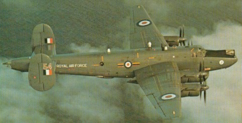
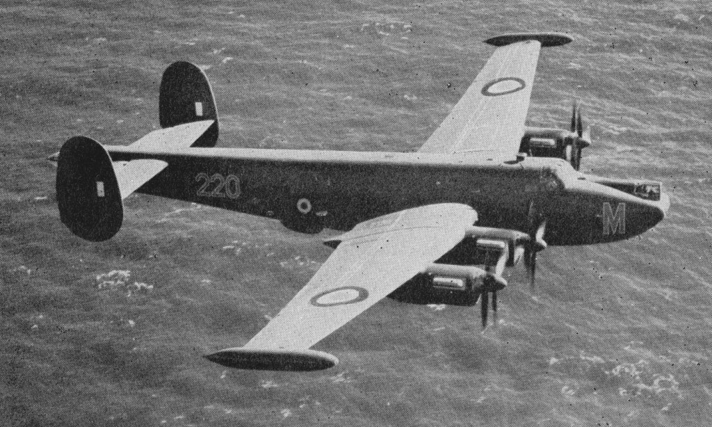
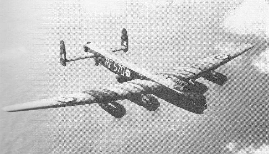
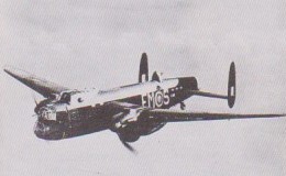
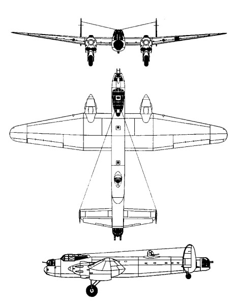
The Shackleton was designed to a 1946 requirement for an all-new long-range maritime patrol aircraft for use by the Royal Air Force Coastal Command. Derived from the Avro Lincoln bomber, The Avro was initially known as the Lincoln ASR.3 and would later become known simply as Type 696 Shackleton (named after English explorer Ernest Shackleton). The Shackleton featured a similar (though all-new) fuselage design and was the first British bomber to feature contra-rotating propeller blades. First flight was achieved on March 9th, 1949.
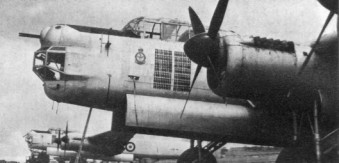
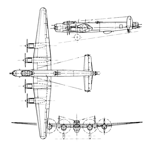
The Avro Shackleton featured a slender straight-sided fuselage with the aft end extended out past the tail plane. The tail plane also featured twin vertical fins in much the same way as that of Lincoln design. The Shackleton was also fitted with a low-wing monoplane with two engines to a wing and each engine was fitted with two three-blade propellers in a contra-rotating fashion – the first such British four-engine aircraft to do so. Power was delivered by 4 x Rolls-Royce Griffon liquid-cooled in-line engines. The Griffons were noted for requiring a great deal of attention during the aircraft’s career. The undercarriage was retractable tricycle, wth twin wheels on each unit. The main wheels retract forward into inner nacelles and the nose whels retract rearward. Armament in the Anti-Submarine Warfare (ASW) role consisted of 2 x 20mm cannons mounted in the nose while internal bombloads could consist of torpedoes, mines and bombs as needed.
The Shackleton MR.1 first flew on 9 March 1949.
Shackleton M.R.1
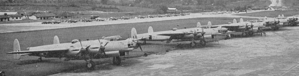
This entered service in April 1951 with No 120 Sqn, based in Scotland, as the Shackleton MR.Mk 1, which was soon complemented by the Shackleton MR.Mk.1A and a production run of 77 Mk.1 and Mk.lA with wider outer nacelles. The radar of the early Shackleton was inadequate, and the Shackleton MR.Mk 2, of which eight examples served with the South African Air Force, introduced a new forward fuselage which retained two 20-mm cannon but relegated the radar from a chin radome to a semi-retractable “dustbin” under the fuselage behind the bomb bay. Additionally, the MR.2 featured a reinforced undercarriage, a lengthened nose and tail section and redesigned tail planes. The first of 69 MR.2 came into use in the UK and Malta in 1952.
Issued in 1957, thirty-four Shackleton MR.Mk 3 introduced tricycle landing gear, a larger fuselage, sleeping galley for the crew on long flights, a revised wing, improved cockpit canopies, dorsal turrets deleted and wing tip-tanks (giving a 24-hour endurance) and, as a retrofit, extra power from two 2,500-lb (1,134-kg) thrust Rolls-Royce Viper Mk 203 turbojets in underwing nacelles, these being noted by their designation of MR.3 “Phase II”.
Shackleton 3
Eight were delivered to the South African Air Force. South African models were in service up until 1984.
In 1964 there were plans to install a pair of Viper 11 jets of 2500 lb thrust in wing pods to improve take-off performance of the Mk.3s.
The last model was the Shackleton AEW.Mk 2 conversion of the MR.Mk 2 for airborne early warning with APS-20 radar in a large “guppy” radome under the forward fuselage. In 1971 No 8 Squadron, RAF, re-formed at Kinloss with MR.3s. 11 remained operational in 1979 with 7 MR.3 serving in South Africa.
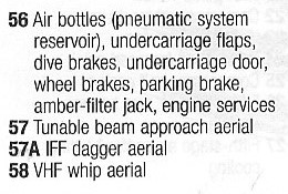
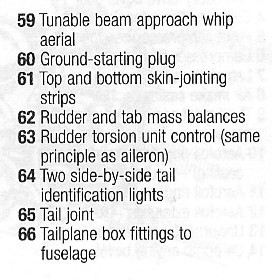
First flown on 28 June 1968 Nimrod MR.Mk 1s began to enter RAF service in October 1969, re¬placing the Avro Shackletons which had assumed this task towards the end of 1951. All marks had either Griffon 57, 57a or 58’s depending upon their modification and phase level.
Shackletons saw their first real use in the Suez Crisis of 1956, the combined British, Israeli and French attack on Egypt after the Egyptian attempt to nationalize the Suez Canal.
In 1964 there were plans to install a pair of Viper 11 jets of 2500 lb thrust in wing pods to improve take-off performance of the Mk.3s.
Production totals for each model type numbered 77 for the Mk 1 series, 70 for the Mk 2 series and 34 for the Mk 3 series with a further 8 of that batch for use in the South African Air Force.
MR.Mk 1 Engines: two Griffon 57 and two Griffon 57A. Wingspan: 120 ft Length: 77 ft 6 in Height: 17 ft 6 in
MR.Mk 1A Engines: four Griffon 57A.
MR.Mk 3 Engines: 4 x 2,455 hp Rolls Royce Griffon.
MR.Mk 2
MR.MR 3 Engines: 4 x Rolls-Royce Griffon 57A inline piston, 2,455-hp (1,831-kW) Wing span 119 ft l0in (36.52 m) Length 92 ft 6in (28.19m) Height 23ft 4in (7.11 m) Wingarea 1,421.0 sq ft (132.01 sq.m) Empty weight 57,800 lb (26,218 kg) Maximum take-off weight 98,000 lb (44,452 kg) Fuel capacity: 4248 Imp.Gal Maximum speed 302 mph (408 kph) at optimum altitude Service ceiling 19,200 ft (5,850 m) Range 4215 miles at 200 mph at 1500 ft Armament: two 20-mm cannons and up to 10,000 lb (4,536 kg) of bombs Crew 10
Engine: 4 x 4 x Rolls-Royce Griffon, 1800kW Take-off weight: 45400 kg / 100090 lb Wingspan: 36.8 m / 121 ft 9 in Length: 26.6 m / 87 ft 3 in Height: 5.3 m / 17 ft 5 in Wing area: 132.4 sq.m / 1425.14 sq ft Max. speed: 485 km/h / 301 mph Cruise speed: 375 km/h / 233 mph Range w/max.fuel: 6000 km / 3728 miles Armament: 2 x 20mm cannons, bombs Crew: 10
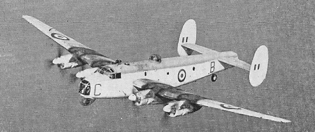
Originally known as the Lancaster Mk.IV, the Avro 694 Lincoln had a slightly longer fuselage, extended-span wings, a revised nose, better defensive firepower and the two-stage Merlins previously used in the high¬speed Lancaster Mk VI.
The Lincoln conformed to Specification B.14/43 and the first prototype flew on 9 June 1944. Normally powered by four Rolls-Royce Merlin 85 engines with annular radiators, the Lincoln was armed with twin 12.7mm Browning machine-guns in a Boulton-Paul Type F nose turret; two 20mm Hispano Mk 4 or Mk 5 cannon in a Bristol B-17 Mk II dorsal turret; twin 12.7mm machine-guns in a Boulton Paul Type D rear turret and up to 6,350kg of bombs.
The war ended just as No. 57 Sqn, the first recipient, was equipping, and the Lincoln became the RAF’s standard post-war heavy bomber.
Avro built 168 production aircraft, plus 79 from Metropolitan-Vickers and 281 from Armstrong Whitworth. Six were also built in Canada and 54 with nose extensions in Australia by the Government Aircraft Factory at Fishermen’s Bend, NSW.
Lincoln B.30
The Lincoln B.30 is an Australian-built version for the RAAF. The first five B .30s were assembled largely from imported British components, the first flying on 17 March 1946, but a further eighty-eight were completely built in Australia, a number being fitted with a lengthened nose to accommodate two additional crew members and search radar. This increases fuselage length by 6 ft. The B.30 has four Commonwealth-built Merlin 102 engines.
Argentine Air Force Lincoln B.1
Thirty Lincolns were also diverted to the Argentine Air Force. Several versions of the bomber were produced during the production runs: Lincoln B.I with Merlin 85 engines; B.2 with Merlin 68A engines; Lincoln Mk 3 intended to be the ASR version but became the Shackleton; Lincoln B.4 with Merlin 85; Lincoln B.15 built in Canada; and Lincoln B.30 Australian version with Merlin 85 or 102 engines. The bomber eventually equipped 20 RAF squadrons. No 97 Squadron and others were detached to Singapore in 1950 for anti-terrorist raids and to Kenya in 1954. One was converted for the bulk uplift of fuel oil and made 45 civil flights during the Berlin Airlift.
On 12 March 1953 at 14.30 hrs Soviet MiGs shot down an Avro Lincoln bomber training aircraft belonging to the RAF. According to the RAF the aircraft was within the bounds of the Hamburg-Berlin Air Corridor, just across the Soviet border, at a hight of 10,000 ft. The Soviet version of the incident stated that the Lincoln was beyond the boundaries and had penetrated 75 miles / 120 km into East Germany. Instructions to land given by the MiG fighters were replied to with machine-gun fire after which the Soviet fighters had opened fire.
ELINT Lincoln of No.192 Squadron RAF
The RAF Lincoln crashed a short distance from the West German border and six out of the seven crew members lost their lives. According to London, the aircraft, which was based at the Central Gunnery School at Leconfield, carried no ammunition, as it was on a ‘routine training flight’. From British articles at the time it could be deduced that the Lincoln crew had purposely provoked an incident in order to disclose listening posts on the ground and to gauge the reactions by aircraft of the Soviet air defences. In those days special ELINT Lincolns of the RAF, belonging to No.192 Squadron and the Central Signals Establishment at Watton, Norfolk, gatered electronic information.
Before withdrawal in 1963 one detached flight operated in Aden. The Lincoln proved to be last piston-engined bomber to serve with the RAF.
RAAF Lincoln B.30
After seven years of operations in Malaya, the No1 Sqn RAAF returned to Australia in mid-1958, taking their Lincoln B.30s with them.
Lincoln Engines: 4 x Rolls-Royce “Merlin 85”, 1305kW Take-off weight: 34020 kg / 75002 lb Empty weight: 19690 kg / 43409 lb Wingspan: 36.58 m / 120 ft 0 in Length: 23.86 m / 78 ft 3 in Height: 5.27 m / 17 ft 3 in Wing area: 132.01 sq.m / 1420.94 sq ft Max. speed: 475 km/h / 295 mph Cruise speed: 345 km/h / 214 mph Range w/max.payload: 2366 km / 1470 miles Armament: 6 x 12.7mm machine-guns, 6350kg of bombs Crew: 7
Avro 694 Lincoln B Mk. I Engine: 4 x Rolls Royce Merlin 85, 1756 hp (1305 kW) Length: 78 ft 3.5 in / 23.86 m Height: 17 ft 3.5 in / 5.27 m Wingspan: 120 ft 0 in / 36.58 m Wing area: 1420.956 sq.ft / 132.01 sq.m Max take off weight: 75014.1 lb / 34020.0 kg Weight empty: 36792.6 lb / 16686.0 kg Fuel capacity: 2950 Imp.Gal Max. speed: 256 kts / 475 km/h / 295 mph at 4570 m (15,000 ft) Cruising speed: 187 kts / 346 km/h Service ceiling: 30495 ft / 9295 m Cruising altitude: 20013 ft / 6100 m Wing load: 52.89 lb/sq.ft / 258.0 kg/sq.m Range: 2546 nm / 4715 km Range (max. weight): 1278 nm / 2366 km Crew: 7 Armament: nose and tail turrets each with two 12.7 mm (0.5 in) guns, dorsal turret with two 12.7 mm (0.5 in) or two 20 mm guns, and occasionally also one 12.7 mm (0.5 in) ventral hand aimed gun; bombload up to 6350 kg (14,000 lb)
Lincoln B.30 Engines: four Commonwealth-built Merlin 102 Wingspan: 120 ft Length: 84 ft 3.5 in Height: 17 ft 3.6 in Loaded weight: 82,000 lb Max speed: 290 mph Cruise: 230 mph Range: 3500 mi
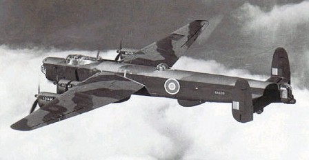
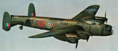
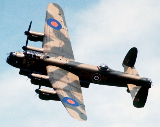
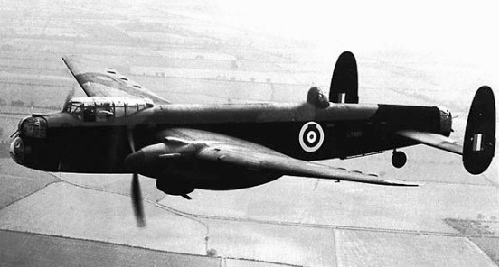
Owing to delays in the full development of the Vulture engine, the decision was taken in mid-1940 to design a new version of the Manchester with four Rolls-Royce Merlin engines. The first conversion made use of about 75 per cent of the Manchester’s parts and assemblies, the principal change being the provision of a new centre-section of the wing with mountings for Merlin engines. This aeroplane became the first prototype of the Lancaster mading its first flight on 9 January 1941. A second prototype fitted with Merlins and significantly modified in detail was designed, built and flown in just eight months.
The first production Lancaster I flew just over five months later, its was powered by four 954kW Rolls-Royce Merlin XX in-line liquid-cooled engines, each driving a three-blade constant-speed and fully feathering propeller.
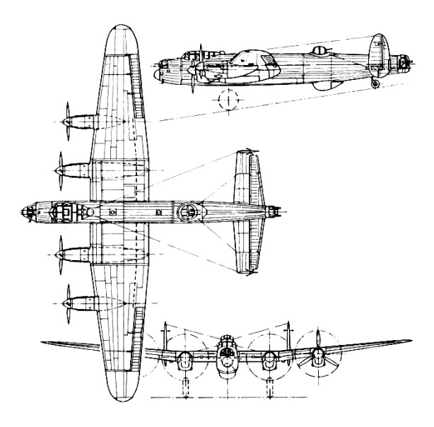
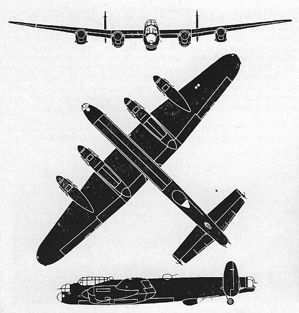
Lancaster I
By 1942, the Mk I was now redesignated with the more traditional B.Mk I naming convention. The system was put into full production at such a pace that the aircraft production lines were outpacing the engine lines. The American Packard company developed the same Merlin engines for shipment back to England. As further insurance, the Bristol company was in line with its own Hercules VI and XVI engines capable of 1,735 horsepower.
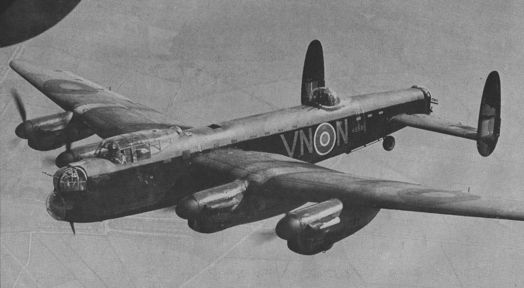
The Lancaster II was built with 1,229.5kW Bristol Hercules VI radial engines but only 300 Lancaster IIs were built. The first of Bomber Command’s squadrons to be equipped with the Lancaster was No 44 based at Waddington, Lincs, in early 1942. No 44 used them operationally for the first time on 3 March 1942 laying mines in the Heligoland Bight. Improving engines provided improving performance: the Lancaster VII, with 1,207kW Merlin 24 engines, had a maximum take-off weight of 30,844kg by comparison with the 22,680kg of the early Lancaster I. The bomb bay was modified progressively to carry the 9,980kg Grand Slam bomb. Six major companies built 7377 aircraft at ten factories on two continents; at the height of production over 1,100,000 men and women were employed working for over 920 companies.
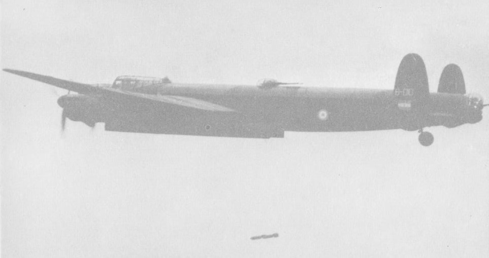
The Lancaster operations included the breaching of the Mohne and Eder dams on the night of 16-17 May 1943 by No 617 Squadron (led by Wing Cdr Guy Gibson); and the sinking of the German battleship Tirpitz.
During World War II 608,612 tons of bombs were delivered in 1156,000 sorties, which represented two-thirds of the total bomb load dropped by the RAF from March 1942 to May 1945. At wars end there were 56 squadrons of Lancasters in RAF Bomber Command.
1944 at Friskerton
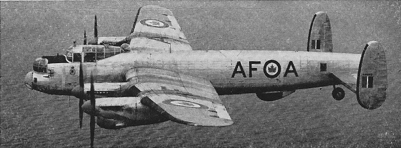
On average Lancasters completed twenty-one missions before being lost. From 1951 until early 1953, France took delivery of 54 reconditioned Lancasters for maritime patrol, general reconnaissance and search and rescue (SAR) work 32 Mk Is and 22 Mk VIIs. In all 13 French Lancasters were destroyed in accidents, or struck off charge following damage. The bulk of the fleet was withdrawn and scrapped with the arrival in strength of the Neptunes in 1958 1959. Others served on with the surviving Escadrilles de Servitude until 1961 1962. It fell to 9S in New Caledonia to be the last French unit to operate Lancasters, giving them up operationally in 1964, ferrying the last two to preservation in April (No 13) and August (No 15) that year. In Canada, 408 Squadron, RCAF, withdrew its last Mk X examples in March 1964 at Rockcliffe.
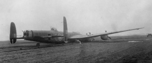
Lancaster 10-MR
Victory Aircraft in Malton (Toronto), Ontario, produced over 400 Lancaster Mk X’s. The basic aircraft built in Canada was the Lancaster 10-B. Eight were converted for photo-reconnaissance as Lancaster 10-Ps in 1948, and others were converted to Lancaster 10-ASR (Air-sea rescue) and 10-BR (Bomber-reconnaissance) during 1949-50. The Lancaster 10-MR maritime reconnaissance aircraft succeeded the 10-BR, the first conversion flying on 29 December 1950.
Of the 7366 Lancasters built, all but 300 radial engines Mk.IIs had Merlin engines of 1460-1640 hp. All carried a crew of seven. 3487 were lost on operations over Germany during WW2.
Avro Lancaster I Engines: 4 x Rolls-Royce Merlin XX, 1280 hp(955 kW) or Rolls-Royce Merlin 22, 1460 hp(1089 kW) or Rolls-Royce Merlin 24, 1640 hp(1223 kW) Wing span: 31.09m Length: 21.18m Height: 6.25m Wing area: 120.49sq.m Empty eight: 16,783 kg MTOW: 30,845 kg Max speed: 44s kph @ 4570m Range: 4072 km Armament: 9 x 7.7 mm Browning mg Bombload: 9979 kg
Avro 683 Lancaster Mk I Engine: 4 x Rolls Royce Merlin XXIV, 1618 hp Length: 69.488 ft / 21.18 m Height: 20.013 ft / 6.1 m Wingspan: 102.001 ft / 31.09 m Wing area: 1296.954 sq.ft / 120.49 sq.m Max take off weight: 70013.2 lb / 31752.0 kg Weight empty: 36907.3 lb / 16738.0 kg Max. speed: 249 kts / 462 km/h Cruising speed: 183 kts / 338 km/h Service ceiling: 24606 ft / 7500 m Cruising altitude: 20013 ft / 6100 m Wing load: 54.12 lb/sq.ft / 264.0 kg/sq.m Range w/max.fuel: 3600 km / 2237 miles Range w/max.payload: 1800 km / 1118 miles Range with 14,000 lb. (6,350 kg.) of bombs: 660 miles (2,700 km.). Crew: 7 Armament: 10x MG 7,7mm, 8185 kg Bombs
Lancaster II Engines: 4 x Bristol Hercules. Length: 70ft.
Lancaster III Length: 69 ft 6 in Wingspan: 102 ft Top speed: 275 mph Armament: 8-10 x .303 mg Bomload: 18,000 lb Crew: 7 Range: 2530 miles
Lancaster X Type 7 Seat Heavy Bomber Engines: 4 x Rolls Royce Merlin 224, 1620 hp Wing Span: 102 ft (31.1 m) Length: 69ft 6″ (21.1 m) “ Height: 20ft 4″ (6.2 m) Speed: 272 Mph (438km/h) Armament: Nose and Dorsal Turrets with two 0.303in Brownings, tail turret four 0.303in Brownings. Bombs-14,000lbs – 22,000lbs with modification
683 Lancaster 10-MR Engines: 4 x Rolls Royce Merlin 224, 1620 hp Empty weight: 41,000 lb Loaded weight: 68,000 lb Max speed: 250 mph Cruise: 216 mph Range: 2250 mi Wingspan: 102 ft Length: 68 ft 10 in Height: 20 ft Wing area: 1297 sq.ft
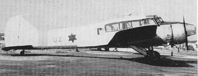
The Avro Manchester was to fulfill Air Ministry Specification P.13/36. The specification called for a twin engine heavy bomber that could sport a multi-purpose payload of bombs or torpedoes.
The Manchester twin engines were underslung on mid-mounted monoplane wings with dihedral outboard of the engines and main wheel undercarriage. The fuselage was of a mostly straight design from nose to tail. The flight deck maintained a good all-around vantage point and featured extensive framing. The empennage was dominated by the identifiable twin vertical fin arrangement common to other Avro designs. The initial production Manchester, however, sported a third vertical tail fin running between the base two and along the rear portion of the upper fuselage. The rear fuselage extended out beyond this assembly, which held the rear gunner’s position.
Crew accommodations amounted to seven personnel. The aircraft was defended by 8 x 7.7mm (.303 caliber) Browning machine guns in various strategic emplacements. Two were fitted to the nose turret while the tail turret mounted no fewer than four of these weapons. The remaining two were positioned in a dorsal turret mounted to the rearward portion of the fuselage. From an offensive standpoint, the Manchester could field up to 10,350lbs of internally-held bombs or torpedoes (2).
Production model specs were quite pedestrian with a top reported speed of 250 miles per hour, a range of 1,200 miles and a service ceiling of just 19,500 feet.
Power for the Manchester was derived from the twin Rolls-Royce Vulture I 24-cylicnder X-type engines of 1,500 horsepower each (initially rated as high as 1,760 horsepower each). This selection of powerplant would eventually become the Manchesters undoing as the engines proved to have a nasty tendency to catch fire when in-flight. Though the same issue greeted the Handley Page Halifax design, forcing the Halifax to become a four-engine bomber utilizing the Rolls-Royce Merlin X series of engines, Avro continued the Manchester design with the Vulture series. By the series operation run, no fewer than 30 Manchesters were lost to engine failures effectively forcing the bomber out of service.
The first Manchester prototype, model L7246, took to the skies for the first time on July 25th, 1939. This aircraft was followed by a second prototype going airborne on May 26th, 1940. The Manchester entered production in this form as the Manchester Mk I model series but was delivered in only 20 such examples. Mk I aircraft joined No. 207 Squadron in November of 1940. Its first mission came about on February 24th, 1941. Manchester Mk IA’s soon followed and were delivered in 200 total examples. These particular Manchesters differed in that they had their central tail fins removed in favor of enlarging the remaining two tail fins. In this form, the Manchester would be most oft-remembered.
At the height of its operational use, the Manchester formed at least eight bomber squadrons and was utilized by RAF Coastal Command as well. The last Manchester mission was recorded on June 25th, 1942. Production ended almost as soon as it had begun, wrapping up in November of 1941.
The Manchester II appeared as a proposed and improved model version of the Manchester series. These Manchester would have sported twin Bristol Centaurus or Napier Sabre engines to make up for the deficiencies inherent in the selected Rolls-Royce Vulture brand engines used in production Manchesters. Unfortunately for the Manchester and Avro, this model series was never produced.
A single Manchester Mk I was pulled aside to undergo a conversion to a new Manchester III standard. This new model design (BT308) featured a greater wingspan incorporating the power of four engines but still retaining the three vertical tail surfaces of the original Manchester. First flight of the recently-dubbed “Lancaster” aircraft was achieved on January 9th, 1941. A follow-up model, the DG595, was debuted shortly thereafter and featured the enlarged twin vertical tail fins of the Manchester IA. This “Manchester III” would essentially become the prototype model of the Avro Lancaster series of multi-engine heavy bombers.
In the end, only 209 Manchesters would ever be completed, with production split between Avro (177) and Metropolitan-Vickers (32).
Canada became the only other Manchester operator during its short-lived service life.
Engines: 4 x Rolls-Royce “Vulture”, 1312kW / 1736 hp Max take off weight: 25401 kg / 56000 lb Empty weight: 13350 kg / 29432 lb Wingspan: 27.46 m / 90 ft 1 in Length: 21.13 m / 69 ft 4 in Height: 5.94 m / 20 ft 6 in Wing area: 105.63 sq.m / 1136.99 sq ft Max. speed: 230 kts / 426 km/h Cruise speed: 298 km/h / 185 mph Service ceiling : 19193 ft / 5850 m Cruising altitude : 14993 ft / 4570 m Wing load: 49.2 lb/sq.ft / 240.0 kg/sq.m Range (max. weight): 2623 km / 1630 miles Crew: 7 Armament: 8 x 7.7mm machine-guns, 4700kg of bombs
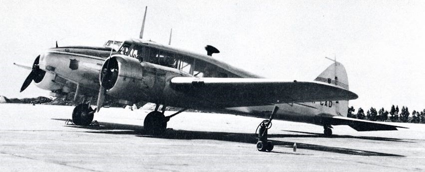
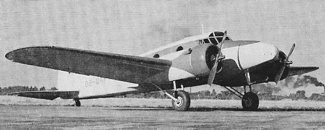
Designed by Roy Chadwick in 1934 the Anson featured twin-engines, a cantilever low-wing with retractable landing gear, and a steel tube fuselage with wooden wings construction. Two were built to an Imperial Airways order of 1933.
The Anson itself was produced to fulfill Specification 18/35 brought about by the British Air Ministry and originally intended for use as a maritime reconnaissance platform. The Anson protoype (Avro 652A, K4771) achieved first flight in this new militarized form on March 24, 1935. Evaluation of the system led to first-run production of the Anson Mk I model series with first deliveries occurring in March of 1936. The Royal Air Force’s No.48 Squadron became the types first user.
The Anson had capabilities that made it useful in the training of pilots, bombardiers and gunners. The arrival of the Second World War sealed the future of the Anson as a primary trainer and multi-role platform for Britain, her Commonwealth nations and nations across the globe.
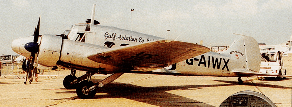
The Avro 652A Anson I was both a general reconnaissance aeroplane and advanced crew and navigation trainer, descended directy from the Avro 657. Only 6 Mk.1 Ansons were delivered from Avro in 1938. The Anson Mk.1s were later re-winged to the Mk.XIX full metal mainplane.
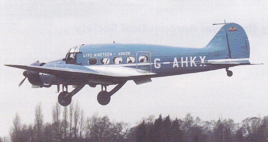
Avro XIX G-AHKX post 20-year restoration flight 8 March 2001
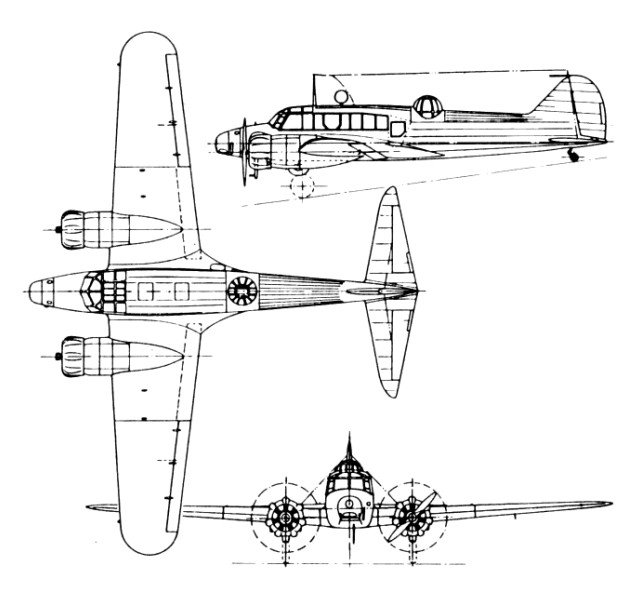
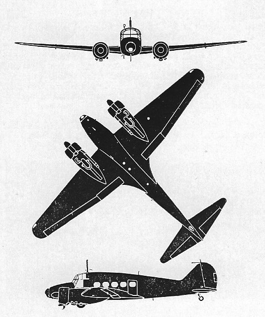
Outwardly, the Anson fuselage was rounded and decidedly streamlined (sometimes showcasing rounded cabin windows – five windows to a side). Perhaps the most distinct feature of the aircraft’s profile was its “duckbill” nose assembly, protruding well past the front windscreen. The aircraft sported low-mounted monoplane wings with rounded wingtips. Each wing held a radial piston engine housed in nacelles powering two-bladed propellers. The engines were placed well-forward of the wing leading edge and met up nearly at the length of the fuselage nose. The undercarriage was typical of the time, featuring two main landing gears and a tail wheel. The main landing gears retracted forward into the bottom of each engine nacelle. The Anson became the first RAF aircraft to feature a fully-retractable undercarriage, this accomplished via a manual hand-crank controlled by the pilot. The empennage was of a conventional sort, with a rounded vertical tail fin and low-mounted horizontal planes. Typical crew accommodations amounted to 3 or 4 personnel. Armament consisted of up to 4 x 7.7mm (.303 cal) Vickers-type machine guns in the front fuselage, a dorsal turret and at two other cabin locations. Additionally, the Anson could be fitted with up to 500lbs of internal ordnance.
The legacy of the Anson was solidified by its sheer production numbers and quantity of variants the line evolved into. The Mk I represented the most quantitative Anson, with 6,688 examples seeing delivery. This version was powered by the Armstrong Siddeley Cheetah series engines of 350 (Cheetah IX) or 395 (Cheetah XIX) horsepower. Maximum speed for Cheetah IX-powered Ansons was reported to be around 188 miles-per-hour with a range topping off at 790 miles. Service ceiling figures put the Anson Mk I at 19,000 feet with a rate-of-climb nearing 750 feet-per-minute.
The production prototype flown in December 1935 was a forerunner of 7,195 Avro-built Anson I for the RAF, RN, RAAF, SAAF, RGAF, Greece and Egypt. Production Ansons were first issued to No 48 Squadron, which put them into service on 6 March 1936. Armament included two 45kg and eight 9kg bombs, a forward-firing Vickers gun and a Lewis gun in a turret amidships.
Operational with Coastal Command between 1936 and 1939 and for air-sea rescue until 1942, the majority were delivered as turretless trainers for the Commonwealth Air Training Plan in Canada, Australia and South Africa. Canadian Car and Foundry became involved in the programme to produce the Avro Anson 1, which had been adopted as the main twin engined trainer for pilots in the British Commonwealth Air Training Programme (BCATP) in Canada. Originally the aircraft were to be assembled in Canada from British components, but problems with shipping and supply caused these plans to be abandoned in 1940. Canada, with a commitment to provide a training scheme, but without the necessary aircraft, was forced to establish its own manufacturing and production programme. Almost all of the Canadian aircraft manufacturers, including CCF, became involved in the production of what was now designated the Anson II, production being co ordinated by Federal Aircraft Ltd, a company specifically formed for that purpose.
Can Car was involved at two levels, producing components as well as entire aircraft. During a two year production period from 1941 to 1943, the company manufactured some 800 wings and 300 fuselages at its plants in Quebec and later produced more than 4,400 Hoover variable pitch propellers to replace the wooden propellers fitted as original equipment. The Anson II built in Canada was basically a copy of the British Anson 1 with Canadian made components and a number of engineering and structural modifications such as the adoption of the Jacobs L6MB engine in place of the Armstrong Siddeley Cheetah, the addition of an engine driven hydraulic system, modifications to the undercarriage and the replacement of some of the metal fittings by moulded plywood components. Can Car built 341 complete aircraft at its new factory in Amherst, Nova Scotia, and it was the prototype from that plant which was the first of the Anson IIs to take to the air in August 1941. In all, 1,832 Anson IIs were built, most destined for the flying schools of the BCATP, although fifty were ordered by the USAAF where they were designated Federal AT 20. The last one left RCAF active service in 1954. Britain took to producing these Ansons as well and designated them as Anson Mk III.
Anson MK IV’s were produced in Britain and fitted Wright Whirlwind engines.
The Anson V variant grew out of experience with the Mk II as well as the Canadian interest in replacing metal structures with the more readily available, cheaper and more easily worked wooden equivalents. The Mk V incorporated the Anson II wing, horizontal tail and undercarriage, but the fuselage was almost completely redesigned and the more powerful Pratt and Whitney R-985 Wasp Junior engines were installed. Apart from the cockpit section, which was of welded steel tube construction covered by plywood panelling, the fuselage consisted of US developed, moulded plywood, monocoque units bolted together, comprising a nose section and three after sections, the rearmost of which included the tail fin. The net result was a fuselage with a larger capacity, which was both warmer and quieter than that of the Anson II. In addition, being aerodynamically cleaner than its predecessor and with more powerful engines, the Mk V had an improved performance in all categories from load to service ceiling. The first Anson V flew in January 1943 and by the time production ceased two years later, 1,048 had been built. Of these, 300 came out of the Can Car plant at Amherst. Like the Mk II, the Anson V saw service with the BCATP, mainly in a navigational training role, although a small number were fitted for communications and photo reconnaissance work. Following the war, the Anson V became a favourite with aerial survey companies in North America, from Mexico to the high Arctic.
The Anson 5, built during the war years by Federal Aircraft Ltd in Canada, differs from British-built Ansons, featuring a Vidal moulded veneer fuselage and two 450 hp Pratt & Whitney R-985 AN-12B or 14B supercharged radials. Production commenced in 1942 as a navigation trainer for the CAF. The Anson 6 was similar but equipped as a gunnery trainer. 1050 Mk.4 and 6 were built.
Anson 5
The post-war series of Anson trainers and transport all possess the raised cabin roof first introduced on the Anson C.11. The majority later received metal wings and tailplane. Of the 326 Mk.19 built, 143 had wooden wings and tail unit, and the remaining aircraft were all metal.
Anson T.20
The Anson Mk VI was a “one-off” Canadian Anson fitting two Pratt & Whitney Wasp Junior engines of 450 horsepower and intended for gunnery and bombardier training.
Anson 10
Increased headroom created the Anson 11 or 12 according to engine. The Anson 10, introduced in 1943, had strengthened floors for continental freight runs by Air Transport Auxiliary. The Anson Mk X represented at least 104 Anson Mk I models converted to the new Mk X designation. Similarly, the Anson Mk 11 was formed from 90 Mk I models conversions. The Anson Mk 12 was well-formed in two-hundred twenty-one new-build production examples along with 20 conversions from Anson Mk I models.
The Anson 12, furnished as a feeder-liner eight-seater, became the Avro 19 Series 1 or Series 2 (tapered metal wing) for the RAF, BEA and civil operators in the UK and abroad.
The Anson Mk XIII was a proposed gunnery trainer that was never put into production. These would have been powered by twin Cheetah XI /XIX series engines. The Mk XIV was another gunner trainer proposal that never saw the light of day. These would have fitted the Cheetah XV series engines. The Mk XVI was to be a navigational trainer and the Mk XV would have been used as a bomber trainer – both of these designs were never put into production.
The Royal Air Force used 264 Ansons as transport and communications platforms under the C 19 designation. Navigational trainers were also fielded, these coming in 252 examples under the T 21 designation. Anson T 22s were 54 radio trainers for the Royal Air Force. RAF Ansons made up 26 squadrons at their peak of usage. Australia was a major Commonwealth operator, utilizing no fewer than 1,028 Ansons up until 1955.
After the war surplus Ansons were sold to civil charter firms and the air forces of Belgium, Holland, Iran, Israel, Norway, Portugal and Saudi Arabia. Development continued during and after the war, culminating in the adaption of the civilian Avro XIX for service use as the Anson C19. With a completely re-designed fuselage, and metal wings and tail plane, this second generation Anson continued in RAF service until 1968. Two production series made up this mark, totaling 56 examples.
Final variants of 1948-49 were twelve communications and reconnaissance Anson 18s (spawned from the Avro XIX) delivered to Afghanistan and the thirteen pilot trainers Anson 18Cs delivered to India; 60 Anson T.20 (perspex nose) for navigation training in Southern Rhodesia; T.21 (metal nose) for the RAF in the UK; and T.22 radio trainer.
A total of 8138 built in the UK (3,881 Ansons at the Avro factory at Yeadon, plus enough parts to build another 900 Ansons) and another 2882 built in Canada, during 17 years of production.
The Avro Anson was produced from 1935 to 1952, to which some total 11,020 examples were built. Avro handled production in Britain with 8,138 total examples being produced there while Canadian Federal Aircraft LTD provided for a further 2,882 examples locally-produced in Canada. The last one was delivered to the Royal Air Force on 15 May 1952, and RAF Ansons were retired as late as 1968, thirty-three years after the type’s inception into service. No fewer than 27 nations across the world ended up fielding the Anson in some form or another.
Anson G-AROE, painted as G-AIWX, left Coventry on 10 March 2000 for France, Italy, Greece, Egypt, Jordan and Saudi Arabia for Gulf Air’s 25 March official anniversary on 25 March.
Avro 652 A Anson Mk I Engine: 2 x Armstrong Siddeley Cheetah Mk IX, 345 hp Length: 42 ft 3 in / 12.88 m Height: 13 ft 1 in / 3.99 m Wingspan: 56 ft 6 in / 17.2 m Wing area: 410.001 sq.ft / 38.09 sqm Max take off weight: 8000 lb / 3629.0 kg Weight empty: 5375.8 lb / 2438.0 kg Max. speed: 164 kts / 303 km/h Cruising speed: 137 kts / 254 km/h Service ceiling: 18996 ft / 5790 m Wing load: 19.48 lb/sq.ft / 95.00 kg/sq.m Range: 686 nm / 1271 km Crew: 3 Armament: 2x MG 7,7mm, 163kg Bomb
Avro Anson C.Mk 1 Engines: 2 x Armstrong Siddeley Cheetah IX 7-cylinder radial, 350hp Length: 42.26ft (12.88m) Width: 56.50ft (17.22m) Height: 13.09ft (3.99m) Maximum Speed: 188mph (303kmh; 164kts) Maximum Range: 808miles (1,300km) Rate-of-Climb: 750ft/min (229m/min) Service Ceiling: 18,999ft (5,791m) Armament: Up to 4 x 7.7mm Vickers machine guns Up to 500lbs of bombs held internally. Accommodation: 3 to 5 Empty Weight: 5,512lbs (2,500kg) Maximum Take-Off Weight: 8,598lbs (3,900kg)
Avro 652A Anson Powerplant: 2 x Pratt & Whitney R-985AN-14 Wasp Jr, 450hp. Wing Span : 56ft 6in (17.2 m) Length : 42ft 3in (12.9 m) Height : 13ft (4 m) Range: 790 mi(1,271 km) Speed : 190 mph 304 km/h
652A Anson C.10 Engines: 2 x 320 hp Armstrong Siddeley Cheetah 9 Wingspan: 56 ft 6 in Length: 4 ft 3 in Empty weight: 6510 lb Loaded weight: 9450 lb Max speed: 188 mph Cruise: 158 mph
Anson T.21 Engines: 2 x 420 hp Armstrong Siddeley Cheetah 15 Wing span: 57 ft 6 in Wing area: 440 sq.ft Length: 42 ft 3 in Height: 13 ft 10 in Empty weight: 7766 lb Loaded weight: 10,306 lb Max speed: 171 mph at 5000 ft ROC: 700 fpm
Anson T.22 Engines: 2 x 420 hp Armstrong Siddeley Cheetah 15 Wing span: 57 ft 6 in Wing area: 440 sq.ft Length: 42 ft 3 in Height: 13 ft 10 in Empty weight: 7766 lb Loaded weight: 10,306 lb Max speed: 171 mph at 5000 ft ROC: 700 fpm
Anson II Engines: 2 x L6MB Jacob.
Anson III Engines: 2 x L6MB Jacob.
Federal Anson 5 Engines: 2 x 450 hp Pratt & Whitney R-985 AN-12B or 14B Wingspan: 56 ft 6 in Wing area: 463 sq.ft Length: 42 ft 3 in Height: 13 ft 1 in Empty weight: 6750 lb Loaded weight: 9450 lb Max speed: 194 mph at 3500 ft Cruise: 150 mph Range: 650 mi
Federal Anson 6 Engines: 2 x 450 hp Pratt & Whitney R-985 AN-12B or 14B Wingspan: 56 ft 6 in Wing area: 463 sq.ft Length: 42 ft 3 in Height: 13 ft 1 in Empty weight: 6750 lb Loaded weight: 9450 lb Max speed: 194 mph at 3500 ft Cruise: 150 mph Range: 650 mi
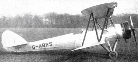
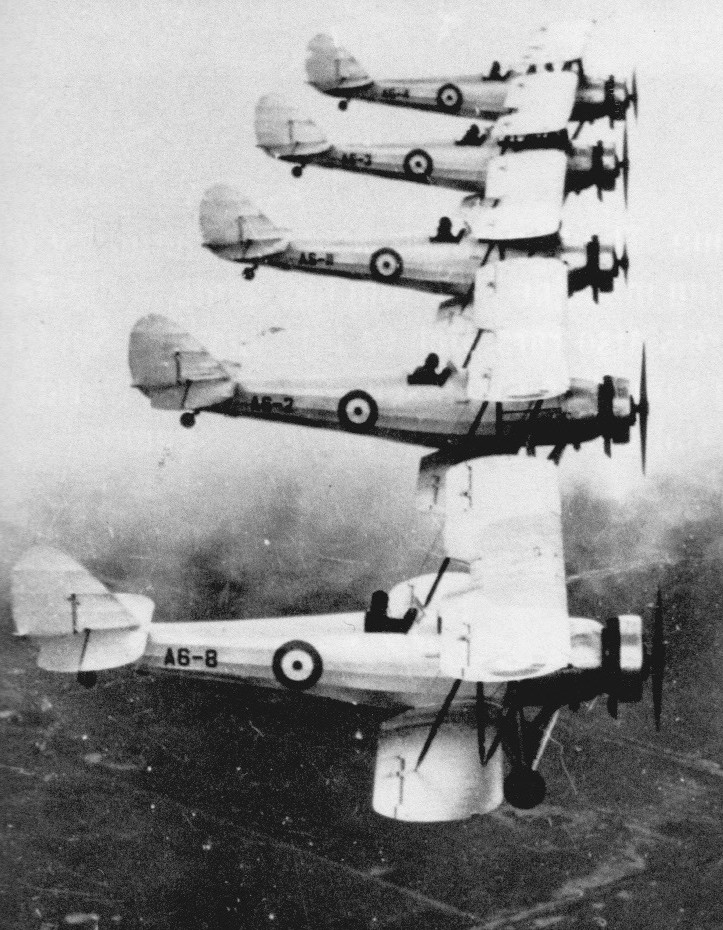
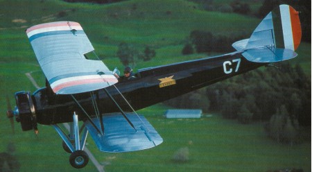
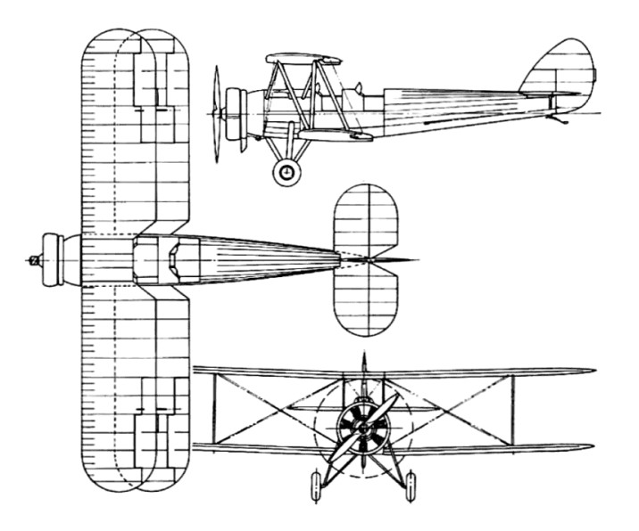
The Avro 631 Cadet was developed in 1931 as a smaller, more economical, derivative of the Tutor military trainer, for flying club or personal use, and the Irish Air Corps purchased six from the drawing board, the first three delivered on 21 March 1932. The first prototype, G-ABRS flew in October 1931. It was publicly unveiled at the opening of Skegness airfield in May 1932. A total of 35 were built.
The Avro 631 also saw service with the military when six (C1-C6) were delivered to the Irish Air Corps in March 1932. One aircraft (C3) was written off in a crash in August 1932 so a replacement was ordered from Avro. This arrived in December 1934 as C7, and it was the only one not destroyed or written off during their service with the IAC. It was subsequently sol in 1945, going through several private owners and at least one crash landing before ending up in New Zealand. There, it was restored to airworthy condition, one of only two Avro 631s left in the world.
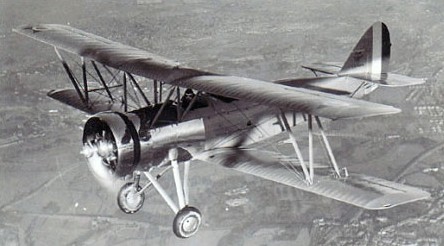
The Avro 631 Cadet was replaced in production in September 1934 by the improved Avro 643 Cadet, which had a revised rear fuselage with a raised rear seat, retaining the 135 hp (101 kW) Armstrong Siddeley Genet Major 1 engine of the Avro 631. In turn, this formed the basis for the more powerful Avro 643 Mk II Cadet with a 150-hp Armstrong Siddeley Genet Major 1A engine mounted 6 inches further forward; it was also strengthened and had improved parachute egress. An inverted fuel system was added and minor modifications were made to the wing bracing wires. This model entered service in 1935, and 69 Cadet IIs were built, including 34 fitted with a tail wheel for the Royal Australian Air Force.
The Cadet, while smaller and more economical than the Tutor, was still more expensive to run than competing two-seat light civil aircraft and was harder to hangar because of its lack of folding wings; so was mainly used as a trainer for flying schools or the military. By far, the largest civil user was Air Service Training Ltd, which operated 17 Avro 631s at Hamble, together with a further four operated by its Hong Kong subsidiary, the Far East Aviation Co. Air Service Training also operated 23 Mk II Cadets, with both these and the earlier Cadets remaining in service with Reserve Training Schools run by Air Service Training until they were impressed as ATC instructional airframes in 1941.
The other major operator was the RAAF, which acquired 34 Mk II Cadets, delivered between November 1935 and February 1939. The RAAF ordered an initial 12 Avro Cadets in 1935. Delivered from December 1935 they were joined by 22 more in 1938-39 while a 1938 order for another 20 was cancelled before deliveries began. These remained in service until 1946, when the surviving 16 were sold for civil use. Two of these were re-engined in 1963 with 220 hp (160 kW) Jacobs R-755 engines for use as crop sprayers. In the U.K., only two Cadets survived the war.
RAAF Avro Cadet
Produced from 1932 to 1939, a total of 104 were built.
Variants
Avro 631 Cadet Initial version, powered by Armstrong Siddeley Genet Major I engine, 35 built.
Avro 643 Cadet Raised rear seat, 8 built.
Avro 643 Cadet II Powered by 150 hp (110 kW) Genet Major 1A, 61 built.
Operators:
Civil operators Air Service Training Ltd
Military operators Royal Australian Air Force operated 34 Avro 643 MkII Cadet. Irish Air Corps operated 7 Avro 631 Cadets. Portuguese Air Force Chinese Nationalist Air Force – China had 5 Avro 631 deployed at Liuzhou Aviation School during the Second Sino-Japanese War, all of which were lost due to Japanese bombing in 1939. Spanish Republican Air Force
Avro 631 Engine: 1 x Armstrong Siddeley Genet Major I. 135hp / 100 kW Wingspan: 9.14 m / 30 ft 0 in Length: 7.54 m / 24 ft 9 in Height: 2.67 m / 8 ft 10 in Wing area: 24.25 sq.m / 261.02 sq ft Take-off weight: 863 kg / 1903 lb Empty weight: 536 kg / 1182 lb Max. speed: 190 km/h / 118 mph Cruise speed: 161 km/h / 100 mph Ceiling: 3962 m / 13000 ft Range: 564 km / 350 miles
Avro 643 Mk II Cadet Engine: 1 × Armstrong Siddeley Genet Major 1A seven cylinder radial, 150 hp (112 kW) Length: 24 ft 9 in (7.55 m) Wingspan: 30 ft 2 in (9.20 m) Height: 8 ft 10 in (2.69 m) Wing area: 262 ft² (24.3 m²) Empty weight: 1,286 lb (585 kg) Loaded weight: 2,000 lb (907 kg) Wing loading: 7.63 lb/ft² (37.4 kg/m²) Power/weight: 0.075 hp/lb (0.12 kW/kg) Maximum speed: 116 mph (101 kn, 187 km/h) Cruise speed: 100 mph (87 kn, 161 km/h) Range: 325 mi (283 nm, 523 km) Service ceiling: 12,000 ft (3,660 m) Rate of climb: 700 ft/min (3.6 m/s) Crew: Two
The Tutor was redesigned as the more multi-purpose Avro 626 trainer. It was essentially still used as a two-seat aircraft, but a third cockpit was aged and had a gun ring fitted to it. This allowed the aircraft to be used for gunnery training.
1930 Moravko-Slezka Vazovka Tatra (Ringhoffer-Tatra) obtained licenses to build the Avro 626 as T.126, and the Bucker Bu 131 Jungmann as the T.131.
Avro 626 Prefect Engine: Armstrong Siddeley Lynx IV C, 237 hp Length: 26.509 ft / 8.08 m Height: 9.58 ft / 2.92 m Wingspan: 33.99 ft / 10.36 m Wing area: 299.993 sq.ft. / 27.87 sq.m Max take off weight: 2749.6 lb / 1247.0 kg Weight empty: 1766.2 lb / 801.0 kg Max. speed: 97 kt / 180 km/h Cruising speed: 83 kt / 153 km/h Service ceiling: 14797 ft / 4510 m Wing load: 9.23 lb/sq.ft / 45.0 kg/sq.m Range: 191 nm / 354 km Crew: 3
Engine: Armstrong Siddeley Cheetah Va, 285 hp. Max speed: 130 mph.
Avro 626 landplane Engine: 1 x 240hp Armstrong Siddeley Lynx IVC Take-off weight: 1249 kg / 2754 lb Empty weight: 801 kg / 1766 lb Wingspan: 10.36 m / 34 ft 0 in Length: 8.08 m / 27 ft 6 in Height: 2.92 m / 10 ft 7 in Wing area: 27.87 sq.m / 299.99 sq ft Max. speed: 180 km/h / 112 mph Cruise speed: 153 km/h / 95 mph Ceiling: 4511 m / 14800 ft Range: 386 km / 240 miles