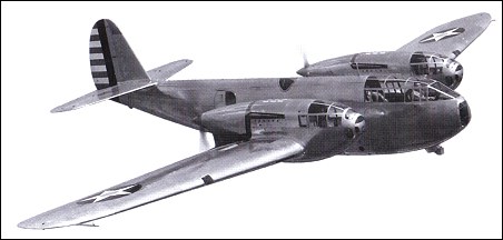
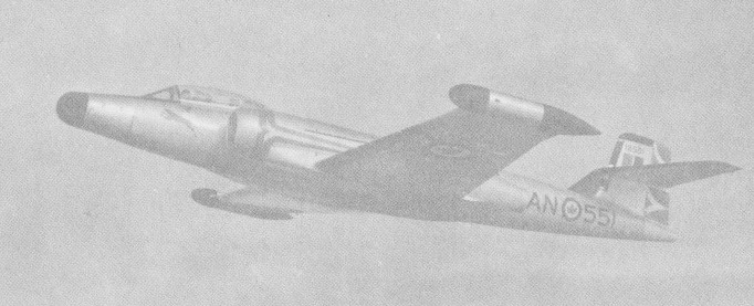
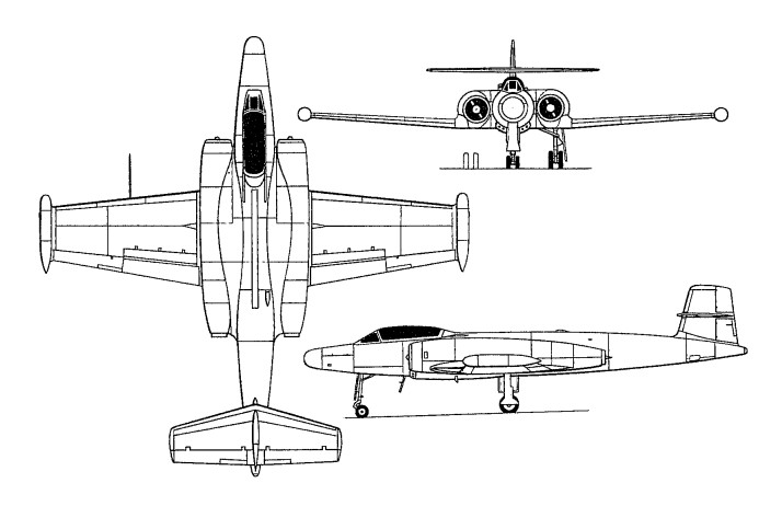
Designed by Robert J Woods, the FM-1 Airacuda was a five-seat long-range bomber destroyer powered by two engines mounted as pushers. The Airacuda accommodated two gunners in forward extensions of the engine nacelles, with access along wing crawlways to the fuselage in the event that it proved necessary to evacuate the nacelle gun positions.
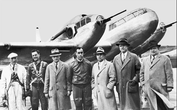
Airacuda with Larry Bell (3rd from right)
Initially, Larry Bell envisioned his aircraft to fly 300 miles per hour at about 20,000 feet with turbosupercharged Allison engines. This was drastically cut when the Air Corps ordered a scaled-down Allison to be used instead with the reason being that the turbosupercharger proved quite volatile and explosive in the YFM-1 when tested. This effectively destroyed any performance the Airacuda could achieve, bring the ceiling down to 12,000 feet and a top speed barely reaching 270 miles per hour.
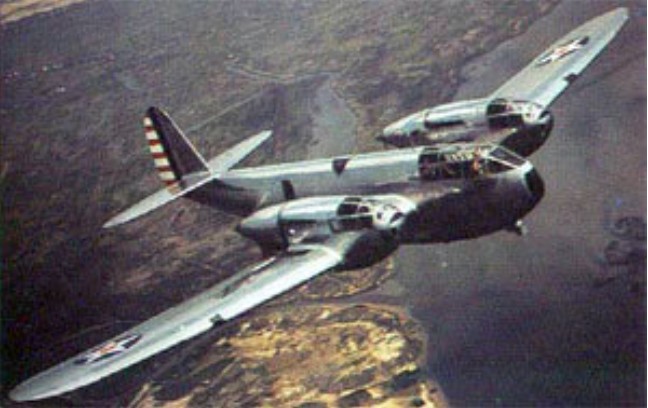
The Airacuda was built around the ability carry a 37mm cannon in each nacelle position, manned by a crewmember. Additional weaponry consisted of 2 x 12.7mm heavy caliber air-cooled machine guns and 2 x 7.62mm general purpose machine guns.
It was found that a considerable amount of smoke filled the nacelle crewmembers position when the 37mm cannon armament was fired.
The prototype, the XFM-1 powered by two 1150hp Allison V-1710-13 12-cylinder liquid-cooled engines driving three-blade propellers via 1.62m extension shafts, was flown on 1 September 1937. Twelve evaluation models were ordered, nine as YFM-1s and three as YFM-1As which differed in having tricycle undercarriages. Power was provided by 1,150hp Allison V-1710-23s, but three YFM-1s were completed with V-1710-41s of 1,090hp as YFM-1Bs. The 12 YFMs were delivered to the USAAC between February and October 1940, and their armament was one 37mm T-9 cannon with 110 rounds in each engine nacelle, one 7.62mm M-2 machine gun with 500 rounds in each of the retractable dorsal turret and ventral tunnel positions, and one 12.7mm M-2 gun firing from each of the port and starboard beam positions. Twenty 13.6kg bombs could be accommodated internally.
Despite the shortcomings – and at least two being lost to accidents – the Airacuda fielded one entire operational squadron though only operating in 1938 through 1940 and were eventually removed from service in 1942 – used as ground crew trainers. Beyond several photo opportunities across the country, the Airacuda never fulfilled its purpose of bomber-interceptor and destroyer and never would see combat action in the Second World War. All were eventually scrapped with only 1 prototype and 12 production models ever existing.
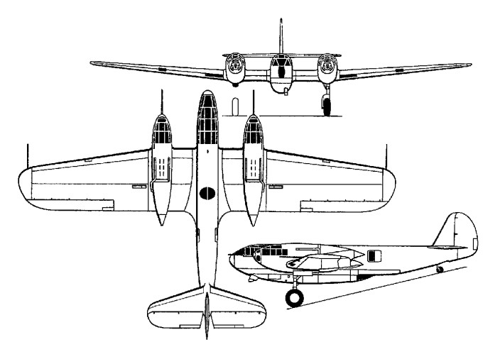
XFM-1 Airacuda Engines: 2 x Allison V-1710-41, 1,150hp each. Length: 44.85ft (13.67m) Width: 69.85ft (21.29m) Height: 13.58ft (4.14m) Empty Weight: 13,375lbs (6,067kg) Maximum Take-Off Weight: 17,333lbs (7,862kg) Maximum Speed: 277mph (446kmh; 241kts) Maximum Range: 2,600miles (4,184km) Service Ceiling: 30,512ft (9,300m) Armament: 2 x 12.7mm machine guns 2 x 7.62mm machine guns 2 x 37mm cannon Bombload: 2 x 300lb Crew: 5 Hardpoints: 2
YFM-1B Take-off weight: 8618 kg / 19000 lb Wingspan: 21.33 m / 69 ft 12 in Length: 14.00 m / 45 ft 11 in Height: 3.78 m / 12 ft 5 in Wing area: 55.74 sq.m / 599.98 sq ft Max. speed: 431 km/h / 268 mph Range: 2687 km / 1670 miles Crew: 5
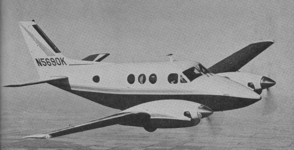
Beech had been working on the model 90 King Air since 1963 (then identified as the Beech Queen Air Model 65-80) utilising the 373kW P&W turboprop PT6 engines. This aircraft was basically a Queen Air fitted with turboprop engines and first flew in January 1964. It proved to be faster than the Twin Otter but still only provided seating for nine passengers. The Model 65-80 designation was confusing as there were Model 65 and Model 80 Queen Airs in production, so the aircraft became known temporarily as the Model 65-90T (T standing for turboprop). In due course, an even better job was made of clarifying the situation by renaming the turboprop-powered Queen Airs as King Airs. In effect, therefore, the Model 65-90T was the prototype for the Beech Model 90 King Air series, but more specifically became the prototype of the unpressurised military Kings Airs.
Announced with a basic price of $300,000, first deliveries were planned for the Fall of 1964. Following the first flight of the Model 65-90T, a civil equivalent was produced in parallel with a pressurised cabin, and the first production prototype of this aircraft, designated Model 90 King Air, flew for the first time on 20 January 1964.
The Pratt & Whitney PT6A-6, 550 shp King Air was fully pressurised.
The first overseas tour for Beech’s King Air started 4 September 1965 with a non-stop Gander, Newfoundland, to Paris flight, first for a plane in this category. Bob Oestreicher, Beech pilot, and Pierre Allain, of Neuchtel, Switzerland, landed at Toussus-Le-Noble Airport near Paris 9 hr 50 min after takeoff. Groundspeed for the 2600 mile trip was 264 mph at 17,000 ft. The only squawk was the clock lost 30 sec over the Atlantic.
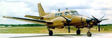
US Army testing of the Model 65-90T, under the military designation NU-8F, had shown the aircraft to be suitable for the military requirement, so an initial order for 48 aircraft, under the designation U-21A (TC 3A20), was placed. Beech distinguished its military King Airs from civil versions by identifying them as Model 65-A90-1, and began modification of the civil aircraft to provide a utility interior. This accommodates a crew of two and 10 troops, or six to eight command personnel, or three stretchers, and seating can be removed easily for the carriage of up to 1361kg of cargo.
Beech U-21A
Initial deliveries of production U-21As, which were given the name Ute, began on 16 May 1967, and subsequent contracts resulted in more than 160 being built. These included U-21As and RU-21A/RU-21D variants all with 410kW Pratt & Whitney PT6A-20 turboprops, and RU-21B/ RU-21C/RU-21E variants with 462kW PT6A-29s. The RU-21s were developed especially for operation in an electronic reconnaissance role in South-East Asia, sprouting a strange collection of aerials and sensors, and being equipped internally with related avionics’ systems, plus nav/com systems suitable for all-weather operations. RU-21Bs and RU-21Cs had Beech designations Model 65-A90-2 and Model 65-A90-3 respectively, and the designation U-21G applied to 17 aircraft for the USAF that were similar to the U-21A. Deliveries of the civil Model 90 King Air began in late 1964, this having cabin pressurisation, and accommodating a maximum of 10 persons, including the pilot. It was superseded in early 1966 by the King Air A90, which introduced the more powerful PT6A-20 engines.
The 90, A90 (first flying in 1966) and B90 are all powered by 500 shp.
The A90 was followed by a King Air B90 with detail improvements in 1970, the B90 was fitted with a 550-shp Pratt & Whitney engines.
In September 1970 by the King Air C90 which introduced a more advanced pressurisation and heating system for the cabin, still with 550-shp Pratt & Whitney engines. The C90 was in production in 1982, with a total close to 1,000 having been delivered by the end of the year. One of these, designated VC-6B, also serves with the USAF’s 1,254th SAM Squadron. The single VC-6A operated by the 89th Military Airlift Wing at Andrews AFB, Maryland, was placed in service in early 1966, and retired in 1985.
Since its introduction, the C90 has been the subject of steady improvement, the 1982 powerplant was the PT6A-21. Ten examples of the C90 serve with the Spanish air force and civil aviation school for instrument training and liaison.
The E90 became part of the lineup in 1972 and employed the 680-shp Pratt & Whitney PT6A-28 turboprop, flat-rated to 410kW. All have full-feathering, reversible propellers. Their pressurized, three-compartment interior can be maintained at sea level atniosphere pressure to flight levels as high as 10,500 feet. The E90 is virtually a more powerful version of the C90. This version remains in production in 1990.
An addition to the King Air line in June 1979 is the F90, a fuel-efficient version, thanks in part to the new Pratt & Whitney engines with improved turbine blades which extract more power from the engine, four blade propellers and full deicing equipment. At 300 mph true air speed it burns less than 70 gallons per hour. Slower-turning props also reduce interior noise levels. This combined the pressurised fuselage of the Model 90, with the wings and tail unit of the Models 100 King Air and 200 Super King Air respectively. The dual wheel gear are fitted with brake deice systems. The pressurization differential of 5.0 pounds/sq.in. provides a sea-level cabin at 11,000 feet. The F90 was powered by 750 shaft horsepower Pratt & Whitney PT6A 135 engines and sold for $954,500.
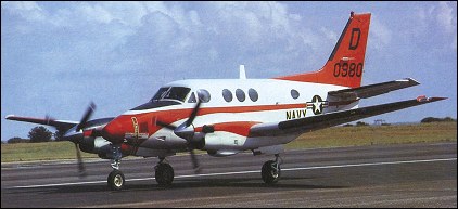
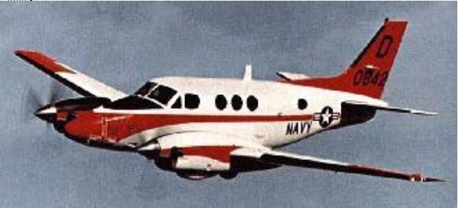
In 1976 the Naval Air Systems Command selected Beech win¬ner of an industry, competition for a three year pur¬chase of new multi engine training aircraft for Naval aviators. The Navy selected an aircraft that combined features of the C90 and E90, designated T 44A. The aircraft is powered by two 550 shp PT6A-34B turbo-prop engines. A total of 15 aircraft purchased by the Navy are to replace piston engine powered TS 2A and TS 2B trainers.
Students selecting the Specialized Undergraduate Pilot Training [SUPT] turboprop track attend T-44 training conducted by the U.S. Navy at Corpus Christi, Texas, and then go on to flying duties in turboprop aircraft. Training includes the Navy common maritime turboprop course followed by an Air Force top-off course. The top-off course consists of single aircraft and formation tactical low level airdrop procedures. Training takes approximately 26 weeks and includes 152 hours ground training, 30 hours in the flight simulator and 111 flying hours in the T-44. The T-44 is equipped with deicing and anti-icing systems augmented by instrumentation and navigation equipment which allows flight under instrument and icing conditions. The interior includes a seating arrangement for an instructor pilot (right seat), a student pilot (left seat), and a second student. Two additional passenger seats are included. A distinguishing feature of the aircraft is the avionics fault insertion capabilities afforded the instructor pilot from the right-seat armrest and the second student/observer audio control panel that allows the second student to monitor all radio communications.
T-44A Pegasus
The T-44A aircraft was procured as a commercial-derivative aircraft certified under an FAA Type Certificate. Throughout its life, the aircraft has been operated and commercially supported by the Navy using FAA processes, procedures and certifications. It continues to be maintained commercially at all levels of maintenance, and relies on COTS/NDI components and equipment to support airworthiness. Aircraft modification efforts are “turnkey” projects (procurement and installation) implemented as part of competitively awarded maintenance contracts. Where extensive integration efforts are required, the non-recurring engineering phase, including test and certification, is typically performed by Raytheon Aircraft Company under a sole-source engineering contract with the Navy.
The 3,000th example of the King Air family was delivered to a customer on 17 April 1981. While production of the F90 ended at 231 aircraft, the C90 continued in production, 1,415 of the low-tailplane variants having been delivered by early 1989.
The Swearingen Taurus was a modified Beech King Air 90 with two 700hp P&W PT6A-135 circa 1986.
B90 Engines two 500-shp Pratt & Whitney turboprops. Seats 6-10. Gross Wt. 9650 lbs. Empty Wt. 5685 lbs. Fuel capacity 384 USG. Cruise 260 mph. Stall 87 mph. Initial climb rate 1900 fpm. Ceiling 27,000 ft. Range 1480 sm. Takeoff distance (50’) 1420 ft. Landing distance (50’) 2300 ft.
C90 King Air First built: 1964. Engines: 2 x P&W PT6A-21, 550 shp. Props: Hartzell 3-blade, 93.4-in. Seats: 6/10. Length: 35.5 ft. Height: 14.3 ft. Wingspan: 50.3 ft. Wing area: 294 sq.ft. Wing aspect ratio: 8.6. Maximum ramp weight: 9705 lbs. Maximum takeoff weight: 9650 lbs. Standard empty weight: 5765 lbs. Maximum useful load: 3940 lbs. Maximum landing weight: 9168 lbs. Wing loading: 32.8 lbs/sq.ft. Power loading: 8.8 lbs/hp. Maximum usable fuel: 2573 lbs. Best rate of climb: 1955 fpm. Service ceiling: 28100 ft. Max pressurisation differential: 4.6 psi. 8000 ft cabin alt @: 21200 ft. Maximum single-engine rate of climb: 539 fpm @ 108 kts. Single-engine climb gradient: 299 ft/nm. Single-engine ceiling: 15050 ft. Maximum speed: 224 kts. Normal cruise @ 18,000ft: 218 kts. Max range cruise: 197 kt. Fuel flow @ normal cruise: 432 pph. Endurance at normal cruise: 5.4 hr Range max fuel/cruise: 881nm/4.0hr. Range max fuel /range: 1251nm/6.4hr. Stalling speed clean: 89 kts. Stalling speed gear/flaps down: 76 kts. 1.3 Vso: 99 kt. Turbulent-air penetration speed: 169 kts.
C90A Cruise: 247 kt. Seats: 10. Range 7 POB & res: 1100 nm
E90 Engine: 2 x P&WAC PT6A-28, 550 hp. TBO: 3500hr. Seats: 10. Wing loading: 34.4 lb/sq.ft. Pwr loading: 9.2 lb/hp. Gross wt: 10,160 lb. Empty wt: 5961 lb. Equipped useful load: 3949 lb. Payload max fuel: 773 lb. Range max fuel/cruise: 1004nm/4hr. Range max fuel /range: 1609nm/7.5hr. Ceiling: 27,620 ft. Max cruise: 248 kt. Max range cruise: 216 kt. Vmc: 86 kt. Stall: 77-86 kt. 1.3 Vso: 100 kt. ROC: 1870 fpm. SE ROC: 470 fpm @ 111 kt. SE ceiling: 14,390 ft. Min field length: 2110 ft. Takeoff distance (50’) 2024 ft. Landing distance (50’) 2110 ft. Fuel cap: 3176 lb / 474 USG. Cabin pressure: 4.6 psi.
F90 King Air First built: 1979. Engines: 2 x P&W PT6A-135, 750 shp / 559kW. Props: Hartzell 4-blade, 92-in. Seats: 6/10. Wingspan: 13.99 m / 45 ft 11 in Length: 12.13 m / 39 ft 10 in Height: 4.8 m / 15 ft 9 in Wing area: 25.98 sq.m / 279.65 sq ft Wing aspect ratio: 7.5. Maximum ramp weight: 11,030 lbs. Maximum takeoff weight: 10,950 lbs. Standard empty weight: 6549 lbs. Maximum useful load: 4481 lbs. Zero fuel wt: 9,600 lbs. Maximum landing weight: 10,950 lbs. Wing loading: 39.1 lbs/sq.ft. Power loading: 7.3 lbs/hp. Maximum usable fuel: 3149 lbs. Best rate of climb: 2380 fpm. Service ceiling: 29,802 ft. Max pressurisation differential: 5 psi. 8000 ft cabin alt @: 23,120 ft. Maximum single-engine rate of climb: 600 fpm @ 117 kts. Single-engine climb gradient: 309 ft/nm. Single-engine ceiling: 14,419 ft. Maximum speed: 267 kts. Normal cruise @ 22,000ft: 257 kts. Fuel flow @ normal cruise: 538 pph. Endurance at normal cruise: 5.3 hrs: Stalling speed clean: 94 kts. Stalling speed gear/flaps down: 77 kts. Turbulent-air penetration speed: 169 kts.
U-21A Ute 1967 Staff transport Engines: two 550hp P&W PT6A-20 Wingspan: 45′ 11 in Length: 35’6″ Useful load: 4220 lb Max speed: 265 mph Range: 1675 mi Seats: 10 No built: 140, 66-18000/18047, 67-18048/18076, -18078/18084, -18086, -18088, -18090/18092, -18094/18103, -18116/18118 4 for electronic warfare as RU-21A, 67-18112/18115 4 modified for electronic reconnaissance as EU-21A, 66-18000, -10803, -18007, 67-18058 2 for ground instruction as GU-21A, 66-18006, -18012 4 for special development tasks as JU-21A, 66-18008, 67-18063, -18065, -18069
RU-21B 1967 Special military applications No built: 3 67-18077, -18087, -18093
RU-21C 1967 Staff transport No built: 2 67-18085, -18089
RU-21D 1967 Modified cockpit No built: 18 67-18104/18111, -18119/18128, plus 18 U-21A conversions
JRU-21D No built: 1 unknown modification 67-18125
RU-21E 1971 Staff transport. No built: 15 70-15875/15890; with 3 modified RU-21D
U-21G 1971 Electronic countermeasures No built: 17 70-15891/15907
RU-21H 1971 Staff transport No built: 32
RU-21J 1972 Battlefield surveillance No built: 20 71-21058/21060 3 modified for a short time from C-12L, then reverted
T-44A Pegasus / H-90 Engines: 2 x P&W-Canada PT6A-34B, 550hp 61 built
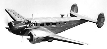
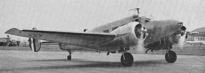
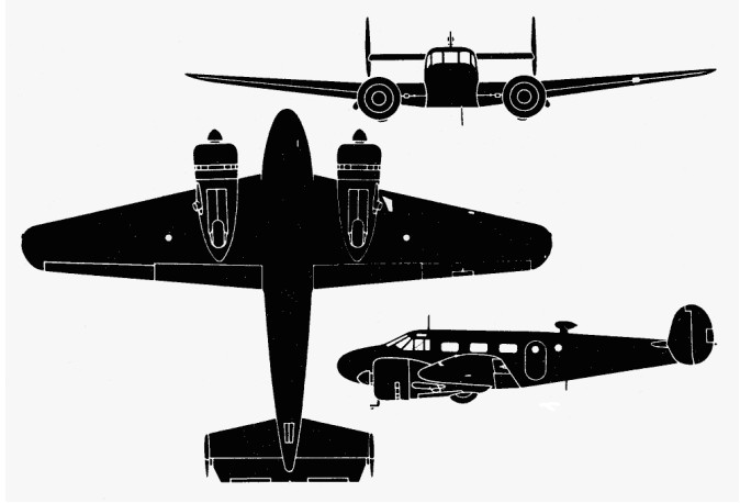
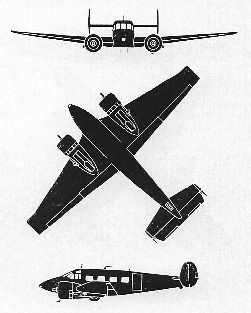
Beech began in 1935 the development of a six/eight-seat commercial transport identified as the Beech Model 18. Designed by Ted Wells, this was a a low-wing monoplane of all-metal construction, with a semi-monocoque fuselage of light alloy, a cantilever tail unit incorporating twin end-plate fins and rudders, and electrically retractable tailwheel landing gear. Float or ski landing gear later became optional. The initial engine installation was two 239kW Wright R-760-E2 radial engines mounted in wing leading-edge nacelles, and accommodation for two crew and six passengers.
The initial 1937 Model 18A (ATC 630) was first flown on 15 January 1937 (certified on 4 March 1937) and the first one, NC15810, was delivered to the Ethyl Corporation in that year at an equipped price of $32,752. It was later converted to a model 18B. About five were built, the rest going to Canada.
An improved Model 18B (ATC 656) with lower-powered 285hp Jacobs engines also sold in small numbers in 1937 for $33,500. Four were built; NC15810, NC18567, NC18569, and NC18583.
By the time war had broken out in Europe, only 39 Model 18 had been sold, even with five versions powered by Wright, Pratt & Whitney and Jacobs engines had been manufactured.
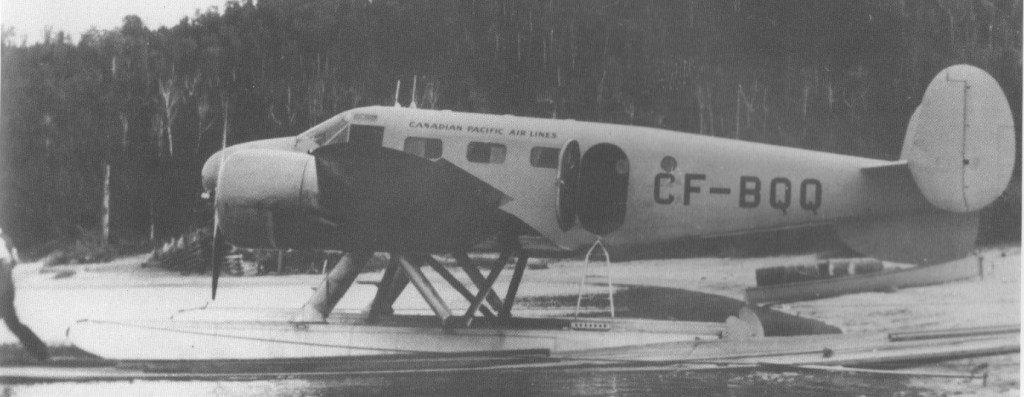
The ability to operate on skis and floats was an advantage in Canada.
A-18A CF-BQQ
The Model D18-C Expeditor could be converted to a Model E18-S if Pratt & Whitney engines replaced the original Continentals.
The Model 18D (ATC 684) of 1939 had 200hp / 246kW Jacobs L-6 engines, giving improved performance. Only 34 of these were sold in 1940, for $37,000 but the wartime demand for these aircraft was to total more than 4,000. A18D also amended under this ATC issued in 1940.
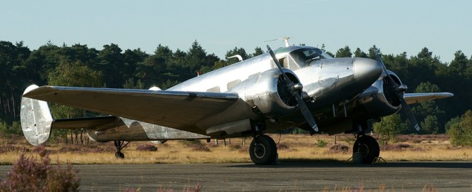
Beech 18G N6B
The first military version was supplied to the Philippine Army Air Corps. Dwight D. Eisenhower, as Chief of Staff of the American mission to the Philipines, selected the Beech 18 for service with the Army Air Corps.
In total the US forces used purchase-built and impressed Model 18s as light transports under the overall designations C-45 (1,401 USAAF aircraft) and JRB (377 US Navy aircraft), the same basic airframe was used in larger numbers as a trainer.
A total of 5,200 1939 18S model (ATC 710) were built going to the Army Air Corp as AT-7, AT-11, C-45, and F-2; and to USN as JRB-1 and SNB-1.
Beech 18-S NC19452
The 1938 A18D (ATC 684) was powered by 330hp Jacobs and sold for $37,000. Sixty-six were built, including SA18D float version under an ATC amendment in 1940.
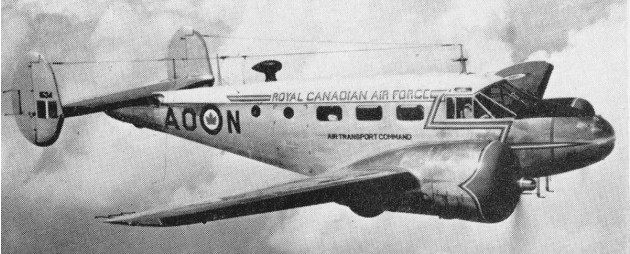
The first US Army Air Corps order, placed during 1940, was for 11 aircraft under the designation C-45, for use as staff transports. These were similar to the civil Model B18S. Subsequent procurement covered 20 C-45As for use in a utility transport role, with interior and equipment changes being made in the 223 C-45Bs that followed. Some of these aircraft were supplied to the UK under Lend-Lease, being designated Expediter I in RAF service. The USAAF designations C-45C, C-45D and C-45E were applied respectively to two impressed B18S civil aircraft, two AT-7s completed for transport duties, and six AT-7Bs similarly modified. Major and final production version for the USAAF was the seven-seat C-45F, with a slightly longer nose and of which at least 1,137 were built. Lend-Lease deliveries served with the Royal Navy and RAF as Expediter Iis, and with the Royal Canadian Air Force as Expediter IIIs. All of the C-45 designations were changed to a new UC-45 category in January 1943.
The RCAF received its first Expeditors in 1939 and flew them until the Services were unified in 1968. Retirement from the Canadian Forces came in 1970.
In 1940 six were delivered to the Nationalist Chinese government as M18R (or AT18R) with bomb racks, machineguns and a bombardier position in the nose, and one delivered to Sweden equipped as a flying hospital. Sixty-one were built with six M-18R appearing on the US civil register (NX25474 to 25479), possibly the Chinese airplanes.
In 1941, the Beech AT-7 Navigator was introduced to provide navigation training, equipped with three positions for trainee navigators, plus a dorsal astrodome and 336-kW (450-hp) R-985-25 radials. A total of 577 were built, being followed by six AT-7As with float landing gear and a large ventral fin. Nine AT-7Bs, basically winterized AT-7s were built to USAAF order: five were supplied to the UK, one being used by Prince Bernard of the Netherlands during his wartime exile. The AT-7C final version of the Navigator had R-985-AN-3 engines, production totalling 549.
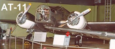
The AT (advanced trainer) version of the Model 18 appeared during 1941. The AT-11 Kansan (originally named Kansas) with R-985-AN-1 engines, for the USAAF was a bombing and gunnery trainer. It incorporated a small bomb bay capable of holding up to 1000 lb of light bombs, had small circular portholes in place of the standard rectangular cabin windows, a redesigned nose to provide a bomb aiming position, and two 7.62mm machine-guns, one in the nose, the other in a dorsal turret.
AT-11 Kansan
The AT-11 was the standard WW II bombing trainer; about 90 percent of the more than 45,000 AAF bombardiers trained in AT-11s. Student bombardiers normally dropped 100-lb. sand-filled practice bombs. In 1943, the AAF established a minimum proficiency standard of 22 percent hits on target for trainees. Combat training missions were flown taking continuous evasive action within a ten-mile radius of the target and final target approaches had to be straight and level and no longer than 60 seconds. After September 30, 1943, these missions were generally flown using the Norden Bombsight and the C-1 automatic pilot, the aircraft being guided by the bombardier student during the bombing run.
Production from 1941 to USAAF orders totalled 1,582 and of them, 36 were converted for navigation training as AT-11As. Twenty-four AT-11s ordered by the Netherlands for service in the Netherlands East Indies were, instead, taken on charge by the USAAF. They were delivered to the Royal Netherlands Military Flying School at Jackson, Mississippi, in early 1942.
The 1942 B18S featured an upgrade interior and electric system. Fourteen went to USAAF as C-45.
The last of the US Army Air Force’s wartime versions of the Beech Model 18 were photographic reconnaissance F-2s. 14 civil Model B18S were purchased and converted with cabin-mounted mapping cameras and oxygen equipment. They were supplemented later by 13 F-2As with four cameras, converted from C-45As, and by 42 F-2Bs, which were conversions from UC-45Fs: these had additional camera ports in both sides of the fuselage.
The 1944 C18S Expediter (ATC 757) sold from $63,000, going to USAAF as C-45/AT-7 and to USN as JRB/SNB.
Beech built a total of 4,526 C-45 military version for the Army Air Forces between 1939 and 1945 in four versions, the AT-7 “Navigator” navigation trainer, the AT-11 “Kansan” bombing-gunnery trainer, the C-45 “Expeditor” utility transport anf the F-2 for aerial photography and mapping. The AT-7 and AT-11 versions were well-known to WW II navigators and bombardiers, for most of these men received their training in these aircraft. Thousands of AAF pilot cadets also were given advanced training in twin-engine Beech airplanes.
The 1947 D18C Feeder Twin (ATC 770) was designed as a short-route air carrier. Powered by 525hp Continental engines, four were built, priced at $64,250. The D18CT Feeder Twin had added equipment, and increased baggage area. Sixteen sold at $64,890.
In June 1948, under a general revision of the USAF designation system, all of the surviving F-2 photo/reconnaissance aircraft were redesignated RC-45A. Similarly, AT-7, AT-7C and AT-11 s dropped their A prefix: at the same time a small number of drone-directors converted from UC-45Fs and given the designation CQ-3 became instead, DC-45Fs.
The US Navy and US Marine Corps used more than 1,500 Model 18s. Initial versions were similar to the US Army’s F-2, this being designated JRB-1, and followed by a JRB-2 transport, and JRB-3s and JRB-4s equivalent to the C-45B and UC-45F respectively. The designations SNB-1 (320 aircraft), SNB-2 (509 aircraft and 376 SNB-2C) and SNB-3 were applied respectively to aircraft that were equivalent to the USAAF’s AT-11, AT-7, and AT-7C. US Navy ambulance and photographic versions were the SNB-2H and SNB-2P respectively; the SNB-3Q was an electronic counter-measures trainer.
During 1951-2, about 900 in-service USAF UC-45E, T-7 and T-11 aircraft were re-manufactured to zero-time condition and modernised, and given the new designations C-45G and C-45H. The C-45G had an autopilot and R-985-AN-3 engines, the C-45H no autopilot and R-985-AN-14B engines. At the same time, US Navy SNB-2s, SNB-2Cs, and SNB-2Ps were remanufactured under the designations SNB-5 and SNB-5P. Later, with introduction of the tri-service unified designation scheme in 1962, in-service SNB aircraft were redesignated TC-45J and RC-45J respectively in the training and photographic roles.
Post war Beech resumed manufacture of the civil Model 18, and in 1953 introduced a larger and improved version of the D18S.
Beech D18S NC80048
Known as the Super 18 (E18S), the prototype was flown for the first time on 10 December 1953. Structural improvements included external refinements to reduce drag, Geisse safety landing gear for cross-wind operations, a separate flight deck, and improved soundproofing. Wingspan was increased and integral steps fitted. All-up weight was increased with the cabin accommodating five to seven passengers. Some were supplied to the French Armee de l’Air.
The 1946 D18S Executive (ATC 765) sold from $63,550 with around 1,000 by 1953. USAF version was the C-45G.
E18S Super 18
The 1953 E18S Executive Super Twin, or Super 18 (ATC 765) first flew on 10 December 1953. Selling for $61,500, 464 were built before replaced in 1962 by the H18. Powered by 450hp P&W R-985 Wasp Jr engines they were nine-place.
The 1959 G18S were an improved E18S with two-piece windshield and a large center cabin window. One hundred and fifty-six were built.
The last of the model 18 were the 1962 H18 ten-place. One hundred and forty-nine were built, priced at $179.500.
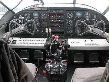
Beech H18 Panel
Progressive improvements continued throughout the production of 754 Super 18s, the last examples of the final Model H18 version being built during 1969. The H18 Super-Liner is an advanced version with more engineering improvements than any previous model, including electric cowl flaps, a redesigned exhaust system, lightweight props, and automatic oil coolers.
In September 1963 Beech introduced optional factory-installed retractable tricycle landing gear which had been developed by Volpar Inc. of Los Angeles, California. Some other options include fuel injection, air conditioning, an autopilot and weather radar. Post-war production of the Model 18 finally come to an end in with the tri-gear H18S Super 18 leaving the factory in 1969. In 1969, the last 10 planes were sold to Japan, ending a 32-year production cycle.
In total, the Beech 18 line had 32 variants, and more than 9,000 civil and military planes had been built when the last one (a Super 18H) rolled off the assembly line on 26 November 1969, accounting for the longest production run in aviation history.
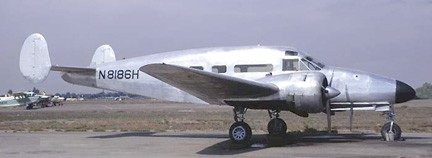
Beech D18S Rausch “headroom” conversion N8186H
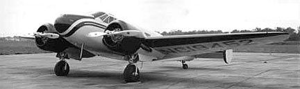
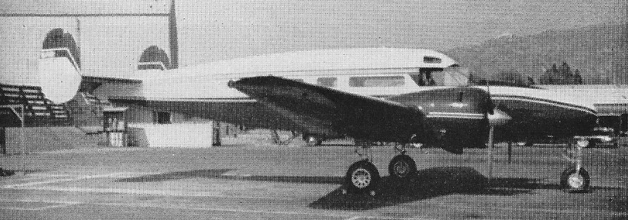
Pacific Airmotive Super 18S N36068
In 1940 Volpar offered conversion of Beechcraft 18 to executive light transport with tricycle or conventional gear, redesigned nose, custom interior etc.
Volpar 18 NC19452
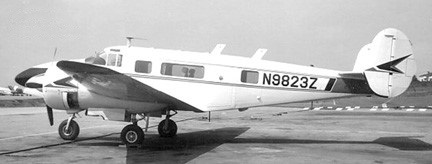
C-45G N8823Z
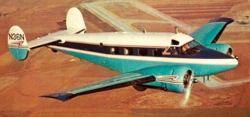
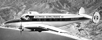
Volpar also offered conversions of standard Beech 18s to Volpar Turbo 18 standard, with tricycle landing gear and TPE331 turboprop engines kits, and also the lengthened turboprop-powered 15-passenger Volpar Turboliner, first flying in December 1964. Conversions offered by other manufacturers have included the nine-passenger Dumod I and 15-passenger Dumod Liner retaining the original Pratt & Whitney R 985 radial piston engines, offered by Dumod Corporation with larger windows and glass-fiber control surfaces; and Pacific Airmotive Corporation’’ 10-passenger PAC Tradewind and turboprop-powered PAC Turbo Tradewind. The Tradewind, a re-manufactured D-18, offering tricycle gear, new windscreen, increased fuel capacity and other updated equipment.
Volpar Super 18 NC343V
Pacific Airmotive Tradewind
Available from Hamilton Aviation in late 1981 were the Hamilton Westwind II STD and Westwind III turboprop-powered conversion of 17-and eight-passenger capacity respectively. The Westwind III was powered by 579 ehp United Aircraft of Canada turboprops. In production for over 32 years, more than 9100 airplanes in 32 variants were built.
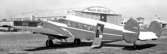
Around 1960 Rausch Engineering modified Beech 18 with a tricycle undercarriage and extended nose. The cabin windows were altered in shape and the fuselage deepened.
Rausch Engineering modified Beech 18
In 1964 Conrad International Corp offer an FAA certified re-worked C-18S, Certified at 10,200 MTOW, modifications at Ft. Lauderdale included tricycle gear, oval passenger windows, airstair door, cargo door and executive interior for nine passengers.
18A Engines: 2 x Wright R-760-E2, 320 hp / 239kW Useful load: 2400 lb Max speed: 202 mph Cruise: 167 mph Cruise: 55 mph Range: 800 mi Crew: 2 Passengers: 6
Beechcraft A-18A 1940 Engines: 2 x Wright Whirlwind, 350 hp Wingspan: 47 ft 8 in Length: 34 ft 3 in Height: 9 ft 5 in Empty weight: 4600 lb MAUW: 7500 lb Cruise: 205 mph Range: 1200 mi Crew: 1-2 Max passengers: 9
18D 1938 Engines: 2 x Jacobs L-6, 300 hp / 246kW Wingspan: 47 ft 8 in Length: 31 ft 11 in Height: 9 ft 5 in Empty weight: 4336 lb MAUW: 7200 lb Cruise: 195 mph Range: 800 mi Crew: 1-2 Max passengers: 9
D18S Engines two 450-hp Pratt & Whitney R-985-AN-14B Wasp Junior. Gross Wt. 8750 lbs. Empty Wt. 5770 lbs. Fuel capacity 206-286 USG. Wing Span: 47ft 7in (14.5m) Length: 32ft (9.74m) Height: 9ft 8in (2.95m) Top speed: 230 mph. Cruise: 211 mph. Stall: 77 mph. Initial climb rate 1190 fpm. Range 985 sm. Ceiling 20,500 ft. Takeoff distance (50’) 1760 ft. Landing distance (50’) 1460 ft. Seats 5-7.
E18S Engines: 2 x Pratt & Whitney R-985, 450 hp. Prop: Hamilton Standard Constant speed 95 in. Pwr loading: 17.7 lbs/hp. Wing span: 49 ft 8 in. Wing area: 310 sq.ft. Wing loading: 31.2 lbs/sq.ft. Length: 35 ft 2.5 in. Height: 10 ft 5 in. Seats: 5 pax. Crew: 2. MTOW: 9700 lbs. Max ldg wt: 9400 lbs. Empty wt: 5910 lbs. Fuel cap: (Std) 198 USG, (with aux.) 318 USG. Max cruise: 214 mph. Maneuvering speed: 153 mph. Stall, clean: 93 mph, Flap & U/c: 84 mph. Vmc: 94 mph. T/o dist: 1455 ft, (50 ft) 1980 ft. Ldg dist: 1036 ft, (50 ft) 1850 ft. ROC S/L: 1410 fpm. SE ROC: 255 fpm. Service ceiling: 21,000 ft. SE Service ceiling: 7750 ft. Max endurance @ 155 mph, std fuel, no res: 4.2 hr, 651 sm. Max range with aux fuel, no res: 6.7 hr, 1038 sm.
C-45 Expeditor / 18S Engines: 2 x 450 h.p. Pratt & Whitney R985-AN-1 Wingspan: 47 ft. 8 in. Length: 33 ft. 11.5 in. Loaded weight: 8,727 lb. Max. Speed: 218 m.p.h. Ceiling: 26,000 ft. Typical range: 1,200 miles at 160 m.p.h. at 5,000 ft. with normal load. Seats: 2 plus 6 passengers.
E18S Super 18 Engines: 2 x Pratt & Whitney R-985-14-ANB Empty weight: 6150 lb Loaded weight: 9300 lb Max speed: 234 mph at 5000 ft Cruise: 207 mph at 5000 ft ROC: 1250 fpm Wingspan: 49 ft 8 in Length: 35 ft 2.5 in Height: 9 ft 6 in Wing area: 361 sq.ft
H18S Super 18 Engines: 2 x Pratt & Whitney R-985-AN-14B, 336kW Take-off weight: 4491 kg / 9901 lb Empty weight: 2651 kg / 5844 lb Fuel capacity: 198-318 USG Wingspan: 15.15 m / 49 ft 8 in Length: 10.73 m / 35 ft 2 in Height: 2.84 m / 9 ft 4 in Wing area: 33.51 sq.m / 360.70 sq ft Max. speed: 354 km/h / 220 mph Cruise speed: 298 km/h / 185 mph Stall: 87 mph Initial climb rate: 1400 fpm Ceiling: 6525 m / 21400 ft Range: 3060 km / 1901 miles Takeoff distance (50’) 2072 ft. Landing distance (50’) 1850 ft. Seats 9-10 Undercarriage: tri-gear
Beechcraft UC-45 Expeditor Engines: 2 x Pratt & Whitney R-985-AN-1 Wasp Junior radial, 450hp each. Length: 34.15ft (10.41m) Width: 47.67ft (14.53m) Height: 9.68ft (2.95m) Maximum Speed: 224mph (360kmh; 194kts) Maximum Range: 1,181miles (1,900km) Rate-of-Climb: 1,850ft/min (564m/min) Service Ceiling: 26,017ft (7,930m) Accommodation: 2 + 8 Empty Weight: 6,173lbs (2,800kg) Maximum Take-Off Weight: 7,496lbs (3,400kg)
C-45A / F-2A / RC-45A / UC-45A Range: 850 mile (with 2,500 pounds of cargo or six pax).
C-45B Expediter I / UC-45B / JRB-3
C-45F Expediter II / Expediter III / F-2B / RC-45A / UC-45F / JRB-4 Seats: 7
AT-7C Navigator / T-7C / SNB-3 Engines: 2 x R-985-AN-3
AT-11 Engine: 2 x Pratt & Whitney R-985-14B
AT-11 Kansan / Kansas / T-11 / SNB-1 six/seven-seat bombing and gunnery trainer Engines: 2 x Pratt & Whitney R-985-AN-1, 336kW (450 hp) Span: 14.50m (47ft 8in). Length: 10.41 m (34ft 2in). Height: 9 ft. 7 3/4 in Max T/O weight: 3959 kg (8,727 lb). Max speed: 215 mph at sea level. Cruising speed: 150 mph Operational range: 850 miles Service Ceiling: 20,000 ft Bomb load: 1000 lb Armament: 2 x 7.62mm (0.3-in) machine-guns Original Cost: $67,000
AT-11A / T-11A Navigation training conversion of AT-11. Engines: 2 x R-985-AN-1
C-45G Engines: 2 x R-985-AN-3, 450 hp Empty weight: 5,785 lb (2624 kg) Loaded weight: 9,000 lb (4082 kg) Span: 47 ft 7 in (14.5 m) Length: 33 ft 11 in (10.3 m) Height: 9 ft 3 in (2.8 m) Wing Area: 349 sq ft (32.4 sq m) Undercarriage: tailwheel.
C-45H Expeditor Engines: Two Pratt & Whitney R-985, 450 hp Span: 47 ft 8 in Length: 34 ft 2 in Height: 9 ft 2 in Max weight: 9,300 lb Maximum speed: 219 mph Cruising speed: 150 mph Range: 1,140 miles Service Ceiling: 18,200 ft Original Cost: $57,838
UC 45J Undercarriage: tricycle
CQ-3 / DC-45F Drone-directors converted from UC-45Fs
SNB-2
SNB-2C
SNB-2H
SNB-2P
SNB-3Q
SNB-5
SNB-5P
TC-45J Trainer
RC-45J Expediter Photographic role
Volpar Turboliner II / Beechcraft 18 Engines: 2 x Garrett TPE 331-1-101B, 705 shp. Seats: 17 Wing loading: 30.75 lb/sq.ft. Pwr loading: 8.15 lb/hp. Max TO wt: 11,500 lb. Empty wt: 6820 lb. Equipped useful load: 4442 lb. Payload max fuel: 206 lb. Range max fuel/cruise: 2041 nm/7.7 hr. Service ceiling: 24,000 ft. Max cruise: 243 kt. Vmc: 84 kt. Stall: 80-84 kt. 1.3 Vso: 104 kt. ROC: 1500 fpm. SE ROC: 225 fpm @ 111 kt. SE ceiling: 13,000 ft. Min field length: 3245 ft. Fuel cap: 2025/3654 lb.
Volpar Turbo 18 / Beechcraft 18 Engines: 2 x Garrett TPE 331-1-101B, 705 shp. Seats: 9. Wing loading: 27.51 lb/sq.ft. Power loading: 7.3 lb/hp. Max TO wt: 10,286 lb. Empty wt: 6200 lb. Equipped useful load: 3844 lb. Payload max fuel: 190 lb. Range max fuel/cruise: 1822 nm/6.5 hr. Service ceiling: 26,000 ft. Max cruise: 253 kt. Vmc: 85 kt. Stall: 77-80 kt. 1.3 Vso: 100 kt. ROC: 1700 fpm. SE ROC: 560 fpm @ 109 kt. SE ceiling: 14,000 ft. Min field length: 2380 ft. Fuel cap: 2025/3654 lb. Undercarriage: tricycle
Dumod I Engines: Pratt & Whitney R 985 radial Passenger capacity: 15
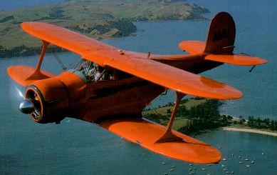
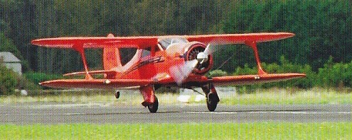
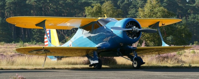
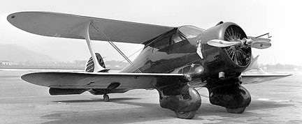
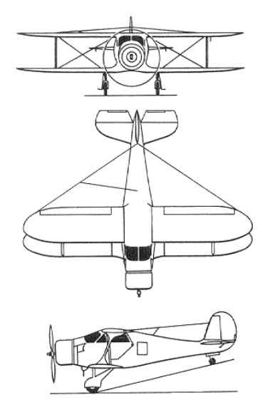
By 1931 Beech resurrected a cabin biplane design started by engineer Ted Wells at Travel Air but rejected by that company’s Curtiss-Wright owners. Aimed at the business executive end of the private owner market — a bold move at the height of the Depression — was the Beech Model 17, continuing the by now-defunct Travel Air series numbers which had ended at CW-16. Apart from its compact dimensions, the four-to-five-seat radial-engine biplane had the unusual layout of its top wing set behind the bottom. This negative or backward stagger arrangement offered several advantages over the more common forward stagger, providing an elegant solution to such problems as pilot visibility and undercarriage location, as well as providing good stall and recovery characteristics.
On paper, the 17 promised to be an airplane of outstanding performance for any category, let alone a four-place commercial biplane. A top speed of 200 mph and landing speed of 60 was what they were looking for. The powerplant would be a 420 hp Wright R-975-E2 radial with a Smith controllable prop. While the narrow landing gear was basically fixed, it has enormous streamlined fairings that al¬lowed room for the wheels themselves to retract 0.15m (6in) in flight. The basic structure was welded steel tube, largely fabric-covered; the braced tail unit was conventional; but with a non-swivelling tail-wheel.
Rather than having a neutral stagger the upper wing stacked directly above the lower wing or a positive stagger, with the upper wing leading, as it did on most biplanes, the 17 had a negative stagger: the lower wing was almost 26 inches farther forward than the upper one. The unique wing configuration had three immediate advantages. Visibility had always been a problem with biplanes and high wing monoplanes, but with the upper lead¬ing edge so far back, the pilot had an excellent view. There was an aerodynamic benefit, too: the center of lift of the upper wing was behind the center of gravity, and that of the lower wing was in front of the CG. The lower wing let go first in an approach to a stall, and since the upper wing was still flying, the rearward cen¬ter of lift would automatically bob the nose down, the plane would pick up speed, and the lower wing would be flying again. At the time, this docile stall was an unusual feature for an airplane of such high performance.
A third benefit of the lower wing’s for¬ward position was that it allowed the gear to be wing mounted rather than attached to the fuselage with drag producing struts and brac¬es. This foresight led to the complete retrac¬tion of the gear into the wing and belly, begin¬ning with the B17 model in 1934.
The nickname Staggerwing was soon coined and shows no signs of going away after almost 65 years. The airframe broke no new structural grounds, having wooden wings and steel tube load-bearing fuselage with wooden formers to carry the aerodynamic shape, all but the forward fuselage covered in fabric. Cessna let his old partner use part of the Cessna plant, temporarily closed by the Depression, to begin building Beechcrafts. Careful attention to streamlining achieved Walter Beech’s specifications of 200 mph top speed while landing at 60 mph, a speed range unknown in 1932, on the 420 hp of a Wright R-975 Whirlwind. On 4 November 1932, six months after the factory opened, test pilot W H “Pete” Hill flew the number one Model 17R, NC499N, at a top speed clocked at 201.2 mph.
Beech 17R NC499N
NC499N was destroyed in a crash on 10 December 1936. In its first two years, the Beech Aircraft Company sold just one airplane, NC58Y. Beech demonstrated the 17R to Tom Loffland who ran a Tulsa oil drilling outfit and had shown an interest during the construction stage. He paid a large deposit and also paid the Beech payrolls while it was being constructed. Work started on the second Model 17 early in 1933, and by July that year the finished aircraft was delivered to its new owner. For his first hundred hours in the airplane, the pilot reported laconically, he had very little idea where it was going during takeoff or landing. It was returned to Beech Co as a trade in mid-1935 and reportedly dismantled
The airplane would have to be improved. As a first step just to see what would happen, he advertised the plane, which already had 420 hp, as available also with the 700 hp Wright Cyclone engine. What happened was an order for one such model from a worsted mill in Maine. Beech built the airplane, but just running up the engine shook the airframe so badly that it continually broke weld joints. In the air it was smoother, and could hit 250 mph, which was faster than any fighter of the time. The pilot who flew it for the customer was given one hundred days to live by his friends, but he confounded them by flying it safely for a year. Thereafter it was sold to Howard Hughes, in whose service it was cracked up on takeoff in the 1937 Bendix Race.
The preproduction model, the A17F with fixed undercarriage, was fitted with a 690-hp Wright R-1820-F11 Cyclone, but although the basic design would appear to give stable flight characteristics, the horsepower was excessive, resulting in “porpoising” due to the short fuselage. There were four fixed gear 17s built – ¬the two 17Rs, an A17F and an A17FS. The A17FS powered with an SR-1820-F3 super-charged Cyclone engine of 710 hp. All stood on tall, stiff, narrow gear and had short coupled fuselages. It was a beautiful airplane in the air but it was very touchy taking off and landing If you were just a second off your timing on the use of the rudder, you were in trouble.
The word on the plane’s high speed spread quickly, and it got a reputation as a hot ship. This notoriety, plus its ground handling characteristics, didn’t help sales. You might also note that the A17F and A17FS had modest little Wright Cyclone engines of 690 and 710 hp, respectively. They went 250 mph, though faster than many military ships and in the air were said to be just as sweet as all models of the Staggerwing were. The A17F, incidentally, was owned at one time by a well known pilot named Howard Hughes.
Meanwhile, Waiter Beech reversed direction, and designed a lightweight, low powered Staggerwing, the B model.
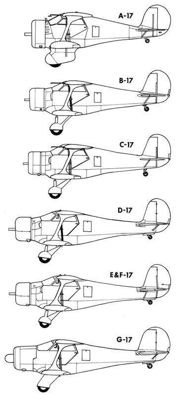
The first production model, built from March 1934 to 1936, was the B17 powered by a 285-hp JacobsR-830-1 L-5 (B17B), a 285-hp Wright R-760-E1 Whirlwind (B17E), a 225-hp Jacobs R-755 L-4 (B17L) or a 420-hp Wright R-975-E2 or 450 hp E3 (B17R). Wingspan was reduced to 32 feet and electrically operated flaps replaced the split rudder for landing drag, but the biggest change was to the undercarriage; a wider, shorter and which now retracted, again by electrical means but with hand-crank backup, folding inwards to house the wheels under the forward fuselage. Other changes included the use of wooden wing spars instead of metal, and a different airfoil. This machine was much more accurately tuned to the market in those still depressed times, and Beech at last began to sell Staggerwings: 18 in 1934 and twice that in 1935 when business began to pick up, as it did for everyone. The Staggerwing had finally achieved commercial success. Commercial success was helped when B17R G-ADLE piloted by H.L.Farquhar completed a 21,332 mile around the world flight in 1935.
Structurally, the Staggerwing uses a mixture of materials and methods. The fuselage has a basic framework of welded steel tube over which is a web of wooden formers and stringers to shape the fabric covering. The wings are all wood: wood spars, wood truss ribs, and, again, fabric skin. The landing gear em¬ploys big metal springs instead of oleos, and is electrically operated. The structure proved strong, except for an era of flutter failures of the top wing, which Beech cured by aileron balancing and plywood stiffening for the wing tips.
The 1936 C model Staggerwing gained a shorter landing gear and had the flaps on the lower wing to improve ground handling which was still a little hairy. A negative four degree angle of incidence was introduced to the tailplane to keep the tail down while landing. Other than these changes, the C17 was identical to the B17, including the choice of engines (with the C17B, E, L and R having the same engines as the respective B17s). Walter Beech never lost an opportunity to market his airplane.
Staggerwings were regularly seen at air shows and did well in racing. The 1936 New York to Los Angeles Bendix cross country race was won by Louise Thaden and copilot Blanche Noyes in a C17R, in 14 hours 44 minutes.
Introduced in 1936 (to 1937), more than 60 C17 were made, but the following year the D17 brought in a number of changes. The most obvious was a rear fuselage extension of 18 inches, while the windscreen profile was altered and the tailplane made a cantilever unit. By now the peripatetic flaps had migrated to their final place on the bottom wing and the ailerons, of similar shape and length, were on the top, while the wings had a new NACA 23012 section and plywood covering outboard of the I-struts. Toe brakes replaced the unloved Johnson bar.
The D17 was built with a range of engines starting with the D17A with 350 hp Wright R-975-E2, followed by the D17R with a 420 hp Wright R-975-E2.
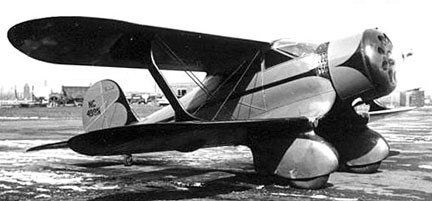
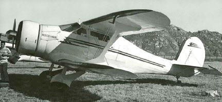
D17S
The most popular model was the D17S introduced in 1937, with a 420-hp Pratt & Whitney R-985 Wasp Junior nine-cylinder, air-cooled radial engine, built from 1937 to 1945. The D-17-S obtained its type certificate on 16 July 1937. 66 of the D-17-S had been sold by the time the US entered WW2.
Wartime production of USAAF UC-43 Traveller (based on the D-17S) and USN GB-1s and GB-2s amounted to 412.
When in 1939 the US Army Air Corps needed a small communications aircraft, the excellent performance of the Model 17 resulted in the procurement of three Model D17s for evaluation under the designation YC-43.
However, it was not until expansion of the USAAF began during 1941-2 that an initial production order for 27 was received, this leading to a total procurement of 207 Beech 17s under the designation UC-43, these being powered by the 336kW Pratt & Whitney R-985-AN-1 engine. After the United States became involved in World War II, an additional 118 civil Model 17s were impressed for military service, and comprising D17R, D17S, F17D, E17B, C17R, D17A, C17B, B17R, C17L, and D17W variants under the respective designations of UC-43A, UC-43B, UC-43C, UC-43D, UC-43E, UC-43F, UC-43G, UC-43H, UC-43J and UC-43K.
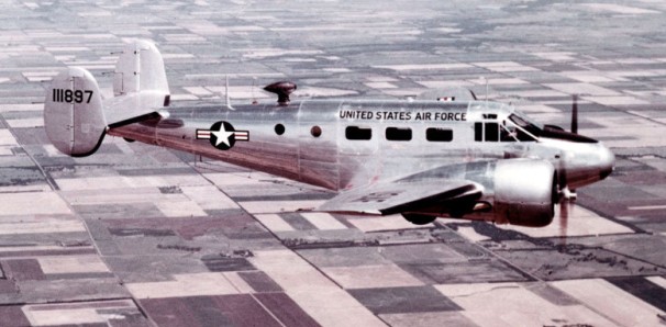
The US Navy had acquired a single example of the Staggerwing as early as 1939. This was a 1937 civil C17R which became designated JB-1 [0801]. The designation GB-1 applied to 10 more, equivalent to the civil D17, acquired in 1939 and, later, to eight civil D17s impressed for military service, plus 63 from USAAF inventory [1589/1595, 1897]. Wartime procurement totalled 342 GB-2s (first flying in 1941), of which 105 were supplied to the UK under Lend-Lease, used primarily by the Royal Navy which named them Traveller, a name adopted also by the US Navy, and the RAF. Some went to Brazil.
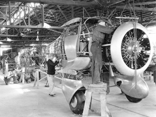
Beech 17R assembly line
The E17, built from 1937 to 1944, and the F17, built for the military from 1938 to 1944, were cheaper versions powered by Jacobs with strut-braced tailplane. A 1940 price list shows that an E17B went for $12,380, while the higher ¬powered D17S listed at $18,870. The price in 1936 was $14,500.
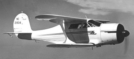
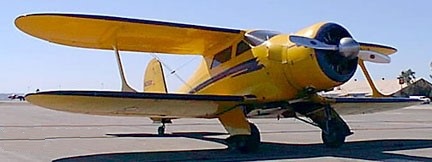
The last in the series was the G17 built from 1946 to 1948. The postwar model was the G17S. Based on the D17S with Pratt & Whitney R-985 Wasp Junior, it was fitted with enclosed gear fairings, cowl flaps, a longer windshield, larger vertical fin, and the engine was moved forward 12 inches with a longer, low-drag engine cowl and more modern disc brakes. At 9700 feet, pulling 65 per cent power, the G17 exceeds 200 mph. Most of the time it cruises at 53 per cent power and 185 mph, burning around 22 gph, with its 450-hp radial. Six fuel tanks (one in each wing, one forward fuselage tank, and one rear fuselage tank) carry 170 gallons to yield a seven-hour endurance or 1300-mile range. Approximately 20 G17 models were built and sold new for $29,000. Its labour-intensive production methods worked against it, especially when Beechcraft introduced its Model 35 Bonanza at only $8,000. Only 20 of the final model were made in 1946, but were not assembled and sold until orders were received over the next two years. The last G17S, serial number B20, assembled from parts in Texas, flew in 1949.
Beech G17 NC21934
In all, a total of 781 Staggerwings were built, of which 353 were commercial and 105 to USAF and 320 to USN, excluding 20 built in Japan as C17E.
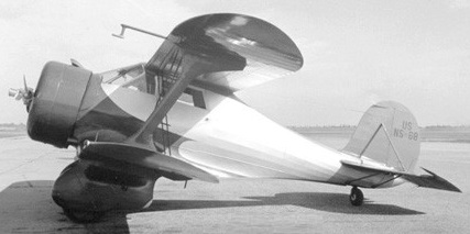
A17FS 1935 (ATC 577) Engine: Wright SR-1820-F3 Cyclone, 710 hp. Wingspan: 34’6″ Length: 24’3″ Max speed: 235 mph Cruise speed: 215 mph Stall speed: 65 mph Range: 750 mi Ceiling: 20,000′ U/C: fixed. Price: $30,000 No built: 1 registered by Beech NR12569 transferred to the Bureau of Commerce as NS68 Dismantled c.1937
Beech A17FS NS68
B17B / SB17B 1934 (ATC 560) Engine: Jacobs R-830-1 (L-5), 285-hp Wingspan: 32 ft Length: 24’6″ Useful load: 1300 lb Max speed: 185 mph Cruise speed: 173 mph Stall speed: 45 mph Range: 500 mi Ceiling: 18,000′ U/C: retractable. Price: $9,000 No built: 2 NC14408, CZ116 CZ116 converted to B17L SB17B was the twin-float designation
B17E 1935 (ATC 566) Engine: Wright R-760-E1 Whirlwind, 285-hp Wingspan: 32 ft Length: 24’5″ Useful load: 1263 lb Max speed: 185 mph Cruise speed: 165 mph Stall speed: 50 mph Range: 680 mi Ceiling: 18,000′ U/C: retractable. Price: $12,980 No built: 4, NC12593, NC14413, NC14458, NC15412 NC14413 converted to B17R
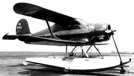
B17L / SB17L 1934 (ATC 560) Engine: Jacobs R-755 L-4, 225-hp. Wingspan: 32 ft. Useful load: 1350 lb Max speed: 166 mph / 282 kph Cruise: 130 kt / 150 mph. Stall speed: 39 kt / 45 mph / 72 kph Range: 560 mi Ceiling: 15,500′ U/C: retractable. Price: $8,000-8,550 No built: 45 the first Staggerwing on floats, SB17L
Beech SB17L NC15402
B17R / UC-43H 1935 (ATC 579) Engine: Wright R-975-E3 Whirlwind, 420-hp. Wingspan: 32 ft. Useful load: 1362 lb Max speed: 211 mph Cruise speed: 202 mph Stall speed: 55 mph Range: 760 mi Ceiling: 22,000′ U/C: retractable. Price: $14,500 No built: 16 3 to USAAF as C-43H 1 converted from B17E, NC14413
Beech B17R NC15815
C17B / SC17B / UC-43G 1936 (ATC 602) Engine: Jacobs L-5, 285 hp Wing span: 32’0″ Length: 24’5″ Max speed: 185 mph Cruise speed: 165 mph Stall speed: 45 mph Range: 480-680 mi Price: $9,250 No built: 39, including conversions to C17L, of which 10 to USAAF as UC-43G 1 built as experimental amphibian NC16440 SC17B was twin-float version
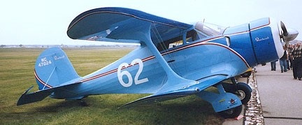
Beech C17B NC47024
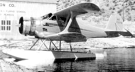
Beech SC17B NC17078
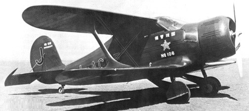
C17E 1936 (ATC 615) Engine: Wright R-760-E1, 285 hp Useful load: 1550 lb Max speed: 185 mph Cruise speed: 165 mph Stall speed: 48 mph Range: 865 mi Seats: 4 No built: 3, NC15487 plus 2 exported to Japan in 1937, incl. NC15836/J-BAOI Japanese construction under license of 20 C17Es from 1938-40
Beech C17E Japanese assembly
C17L / UC-43J 1936 (ATC 602) Engine: Jacobs L-4, 225hp Wing span 32ft MAUW 3165lbs Useful load: 1340 lb Max speed: 175mph. Cruise speed: 166 mph Stall speed: 45 mph Range: 560 mi Price: $8,550 Seats: 4 U/C: retractable No built: 5, of which 3 to USAAF as UC-43J, 1 converted to C17B, NC16441
Beech C17L NC15846
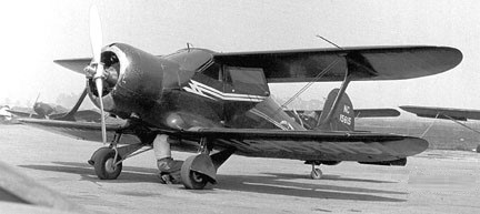
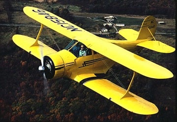
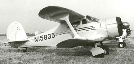
C17R / UC-43E / JB-1 1936 (ATC 604) Engine: Wright R-975-E2, 420 hp Wingspan: 32’0″ Length: 24’5″ Useful load: 1650 lb Max speed: 211 mph Cruise speed: 185 mph Stall speed: 59 mph Range: 800 mi Seats: 4 U/C: retractable Price: $14,500 No built: 17 of which 1 to USN as JB-1, and five to USAAF as UC-43E Winner of 1936 Bendix Trophy [NC15835] (p: Louise Thaden & Blanche Noyes) SC17R with Edo ponyoons.
Beech C17R N15835
D17 / GB-1
D17A / UC-43F 1939 (ATC 713) Engine: Wright R-975-3, 350 hp Wingspan: 32’0″ Length: 26’11” Useful load: 1733 lb Max speed: 180 mph Cruise speed: 170 mph Stall speed: 50 mph Range: 850 mi Price: $16,350 Seats: 4 U/C: retractable No built: 8, of which 1 to USAAF as UC-43F First of the lengthened fuselage models (D-17 through E-17)
Beech D17A NC582
D17R / UC-43A 1937 (ATC 638) Engine: Wright, 420 hp Wingspan: 32’0″ Length: 26’11” Useful load: 1680 lb Max speed: 211 mph Cruise speed: 202 mph Stall speed: 60 mph Range: 825 mi Seats: 4 U/C: retractable Price: $18,870 No built: 28, of which 13 to USAAF as UC-43A, plus 2 conversions from D17W – NC17081, NR18562
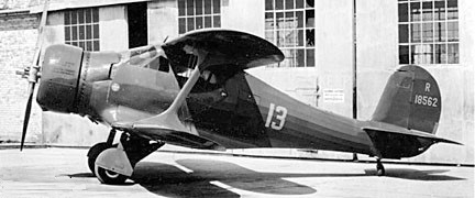
D17S / UC-43B / SD17S / GB-1 1937 (ATC 649) Engine: Pratt &Whitney R 985-AN-1 Wasp Junior, 424 hp Span: 32ft (9.75m) Wing area: 296.01 sq.ft / 27.5 sq.m Wing load: 15.79 lb/sq.ft / 77.0 kg/sq.m Length: 25ft 9in (7.85m) Height: 10.236 ft / 3.12 m Max take off weight: 4681.2 lb / 2123.0 kg Weight empty: 3084.8 lb / 1399.0 kg Max speed: 212mph (341kmh) Cruising speed 65%: 148 kt / 274 km/h / 202 mph Vne: 256mph. Stall: 61 mph. Service ceiling: 19997 ft / 6095 m Range: 840 miles (1350 km) Seats: 4 U/C: retractable Price: $18,870 No built: about 50, of which 13 to USAAF as UC-43/UC-43B, 11 to USN as GB-1 SD17S was floatplane The last D17S NC34R became prototype for G17S
Beech SD17S NC18562
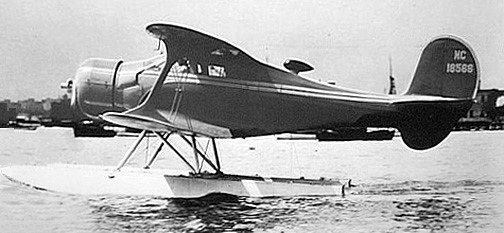
D17W / UC-43K / GB-1 1937 Engine: supercharged P&W R-985-SC-G Wasp, 525-600 hp Seats: 4 U/C: retractable No built: 2 1 for Jacqueline Cochran to set speed and altitude records in 1937-38 – NX/NR18562 1 for Frank Hawks, NC17081, later repowered with 420hp Wright R-975 Both converted to D17R, the NX/NR18562 serving in USAAF as UC-43K, NC17081 serving in USN as GB-1
Beech D17W NC18562
E17B / UC-43D / SE17B 1937 (ATC 641) Engine: Jacobs L-5, 285 hp Wingspan: 32’0″ Length: 25’11” Useful load: 1270 lb Max speed: 188 mph Cruise speed: 177 mph Stall speed: 50 mph Range: 700 mi Seats: 4-5 U/C: retractable Price 1937: $10,490 Price 1939: $12,380 No built: about 52, of which 31 to USAAF as UC-43D
E17L 1937 (ATC 641) Engine: Jacobs L-4, 225 hp Useful load: 1335 lb Max speed: 175 mph Cruise speed: 166 mph Stall speed: 50 mph Seats: 4 U/C: retractable No built: about 3 – CF-BHA, NC17071, NC18785 Similar to E17B
Beech E17L N41663
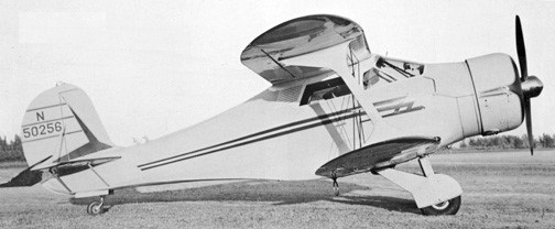
F17D / UC-43C 1938 (ATC 689) Engine make/model: 915-cu Jacobs L6MB, 330 hp Wingspan: 32 ft Length: 25 ft 11.5 in. Height: 8 ft Wing area: 296.5 sq. ft Max gross weight: 3550–3590lb Empty weight, std: 2155lb Fuel capacity: 125 USgals Wing loading: 10.75 lbs./hp Seating capacity: 6 Cruise speed: 182 kts Max speed: 195 mph Cruise speed: 18 mph Stall speed: 50 mph Range: 600 sm Rate of climb: 1300 fpm Service ceiling: 18,000 ft U/C: retractable Upper-wing ailerons, lower-wing flaps Price: $13,980 No built: about 60, of which 38 to USAAF as UC-43C
Beech F17D NC50256
G-17S 1946 (ATC 779) Engine: 1 x Pratt & Whitney R-985-AN-4 Wasp Junior, 336kW / 450 hp Max Take-off weight: 1928 kg / 4251 lb Empty weight: 1270 kg / 2800 lb Useful load: 1,450 lbs. Wingspan: 9.75 m / 32 ft 0 in Length: 8.15 m / 26 ft 9 in Height: 2.44 m / 8 ft 0 in Wing area: 27.65 sq.m / 297.62 sq ft Max. speed: 341 km/h / 212 mph Max cruise (65% @ 9,700ft.): 175 kts. Cruise speed: 298 km/h / 185 mph Normal cruise (53% @ 9,500 ft.): 161 kts. Stall: 60 mph Fuel consumption @ normal cruise: 22 USG/hr. Range @ normal cruise, no res: 1,242 nm. Seats: 4-5 Fuel capacity: 170 USgals Initial climb rate: 1,500 fpm Service ceiling: 20,000 ft Takeoff distance, 50 ft.: 1,130 ft Landing distance, 50 ft.: 980 ft Baggage capacity: 125 lbs. Endurance: 7 hour Range: 1300 sm Price: $29,000 U/C: retractable No built: 17 to 20 Post-war model, and last of the “Staggerwings,” the final one built in 1949 – NC80321
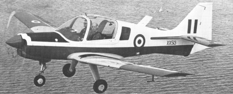
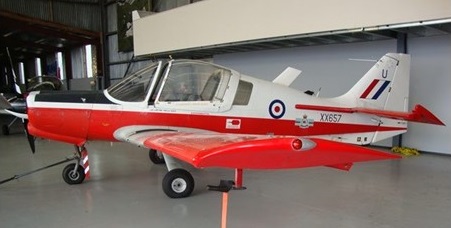
A military version of the Pup was developed after being assessed by Rolls Royce Test Pilot Graham Andrews, who made 12 recommendations including its adaptation to a twin seated aircraft suitable for training purposes. The aircraft evolved into the Beagle B.125 Bulldog with a 200 hp (150 kW) Lycoming engine. Only one prototype aircraft was built by Beagle (with another largely complete) before it ceased operations; the design and production was taken over by Scottish Aviation.
The Bulldog development of the B121 Pup was designed by Beagle as the B125, the prototype G-AXEH (c/n 001) flying from Shorehamon May 19,1969. Following Beagle’s collapse Scottish Aviation took over design and production rights in May 1970 and moved manufacturing facilities to Prestwick. SAL flew the second prototype G-AXIG (c/n 002) on February 14, 1971, in the colours of the Swedish Air Force. The third airframe (c/n 003) was used for ground structural testing. Designated the Bulldog Series 100, the first production aircraft G-AYWN (c/n BH100-101) was flown on June 22 as the first Bulldog for Sweden, serialled 61001, and operated in Sweden as the Sk61. It was followed by the second for Sweden, G-AYWO/61002 (c/n BH100-102), on July 14, both being delivered on July 26. Further allocations are G-AYWP, ‘YZL, ‘YZM and G-AZAK to ZAT, respectively BH100-103 to 114 and serialled 61003 to 61015. These are all known as Model 101. Following on the production line are the first Model 102s for the Malaysian Air Force, BH100-115 and 116. In 1971 orders were for 58 Bulldogs for Sweden, 15 for Malaysia and five for Kenya.
Bulldog Mk.1
In 1973, Finnaviation received a research and development contract from the Swedish Air Force to design skis for their primary trainer, Beagle Bulldog. The Swedes had developed a unique bottom shape for the skis around which an aerodynamic casing and load carrying structure of fiberglass epoxy laminate was designed. The skis were test loaded in the Helsinki University of Techonology structures lab.
Beagle, tried to get its two airplane line accepted in the U.S. The Pup, was expensive, slow for such a clean appearing airframe, and was against the most difficult market for an import the low cost basic trainers. Beagle Aircraft Limited went into receivership and production ceased in 1982.
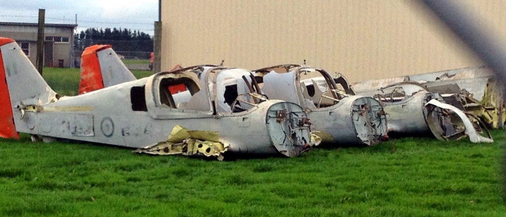
Following delivery in 1981 of a follow-on batch of five Bulldog 125s to the Royal Jordanian Air Force, a further order for five was placed, making 23 in all. In 1981 the Nigerian Air Force ordered another four Bulldog 123s to bring its total to 36.
In 2014, Ex-Nigerian Air Force Bulldogs were sold as scrap and shipped to Palmerston North, New Zealand, for rebuild or resale.
Beagle B 125 Bulldog Engine: Avco Lycoming IO-360-A1B6 Length: 23.261 ft / 7.09 m Wingspan: 33.005 ft / 10.06 m Max take off weight: 2350.5 lb / 1066.0 kg Max. speed: 130 kts / 241 km/h Range: 540 nm / 1000 km Crew: 2+1
B.121 Pup 150 Engine: Lycoming, 150hp. Wing span: 31 ft 0 in (9.45 m). Length: 22 ft 9 in (6.93 m). Height: 8 ft 6 in (2.59 m). Max TO wt: 1600 lb (725 kg). Max level speed: 153 mph (246 kph).
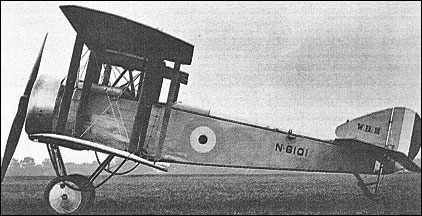
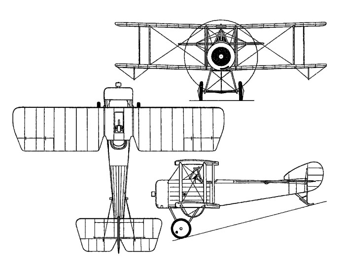
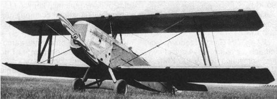
William Beardmore and Co developed their W.B.III as a carrier version of the Sopwith Pup fighter with manually-folding mainplanes and folding main undercarriage members. The William Beardmore and Company firm was already under contract to produce the land-based Sopwith Pup, this under legal license, and developed the WB III for shipboard use by the Royal Naval Air Service during World War 1.
Design of the WB III was conventional for biplane fighter aircraft of the time, keeping up with features as found on the Sopwith Pup. The engine was held in a forward compartment at the front of the slab-sided fuselage. A cylindrical engine cowling was fitted over the front engine facing for a more streamlined approach. The engine, a single nine-cylinder Le Rhone 9C series engine or a seven-cylinder Clerget (each delivering up to 80 horsepower), turned a two-bladed wooden propeller. The biplane wing arrangement featured straight parallel struts unlike the Sopwith Pup’s staggered formation, necessitated by the Navy requirement for manually folding wings (space on aircraft carriers was always at a premium). Additionally, the undercarriage – consisting of two fixed single-wheeled members – could be removed by the ground crew for improved stowage while the tail was supported by a simplistic tail skid. The fuselage tapered off to the empennage to which was affixed a rounded vertical tail fin and applicable horizontal planes.
Performance from the available powerplant allowed for a top speed of up to 103 miles per hour with a service ceiling of up to 12,400 feet and a rate-of-climb equal to 534 feet per minute. Endurance time (essentially the aircraft’s operational range) was listed at 2 hours and 45 minutes. The WB.III maintained a wingspan of 25 feet with a running length of 20 feet, 3 inches. She sat with an 8 foot, 1 inch height. On empty, she weighed in at 890lbs and could take off with a weight of up to 1,290 lbs. Armament was a single fixed, upward-firing .303 Lewis machine gun, firing through a cut-out section of the upper wing assembly.
The prototype WB III (a modified Pup) was accepted by the British military on February 7th, 1917. A contract for 100 production examples soon followed under the official British designation of SB 3.
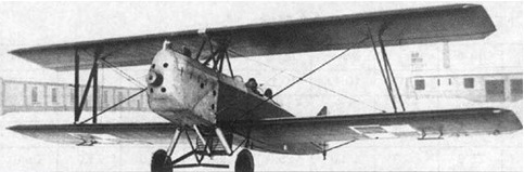
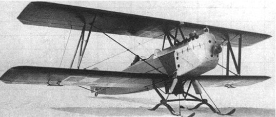
Armament comprised a single 7.7mm Lewis gun which fired upwards through a cut-out in the upper wing centre section, and the W.B.III could be fitted with either the seven-cylinder Clerget or nine cylinder Le Rhone 9C rotary, both of 80hp. The first 13 production W.B.IIIs had folding undercarriages similar to the prototype and were known as S.B.3Fs, but subsequent W.B.Ills had jettisonable undercarriages (S.B.3D) and flotation equipment.
The initial production models fell under the designation of SB 3F and covered some thirteen examples until supplanted by the revised SB 3D. The SB 3D sported a jettisonable undercarriage as well as emergency flotation equipment in a slightly lengthened fuselage.
The WB III served on only three Royal aircraft carriers, these being the HMS Furious, HMS Nairana and the HMS Pegasus. One S.B.3D was used in an unsuccessful attempt to fly from the forecastle of the battle cruiser HMS Renown. Japan became the only other notable operator of the WB III/SB 3 series.
Beardmore SB 3F Engine: 1 x Le Rhone 9C OR 1 x Clerget rotary, 80 hp Length: 20 ft 3 in (6.16m) Wingspan: 25.00ft (7.62m) Height: 8 ft 1 in (2.47m) Wing area: 22.57 sq.m / 242.94 sq ft Maximum Speed: 103mph (166kmh; 90kts) Maximum Range: 171miles (275km) Rate-of-Climb: 534ft/min (163m/min) Service Ceiling: 12,402ft (3,780m) Armament: 1 x 7.7mm (0.303 caliber) Lewis machine gun Accommodation: 1 Empty Weight: 891lbs (404kg) Maximum Take-Off Weight: 1,290lbs (585kg)
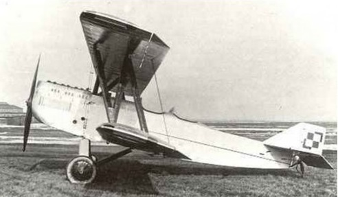
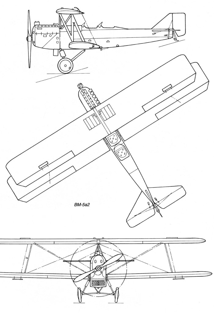
The Bartel BM-5 was designed by Ryszard Bartel with Z. Nowakowski , J. Medwecki , S. Nowkuński in the Samolot factory in Poznań, as an advanced trainer, transitory between primary trainers and bomber or reconnaissance aircraft.
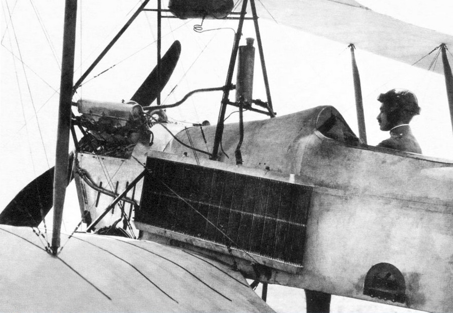
A further development of the Bartel BM-3, it was a wooden construction biplane, the fuselage was rectangular in cross-section, plywood covered (engine section – aluminum covered). Rectangular two-spar wings, plywood and canvas covered. Crew of two, sitting in tandem in open cockpits, with individual windshields and twin controls, instructor in rear cockpit. Fixed landing gear, with a rear skid. Engine in front, with a water radiator below fuselage nose (BM-4a,b,c). Two-blade wooden propeller. Fuel tanks in upper wings and fuselage, capacity: 235-270 t.
BM-5a1
The upper panels were identical to the bottom and braced with N steel pipe and wood double links. Upper panels attached to the hull placed on the pyramid of 6 steel pipes and wood. Ailerons on all wings, covered with plywood. The fuselage of rectangular cross-section rounded at the top, was covered with plywood. The front part of the fuselage covered with removable end caps made of aluminum sheet. Trapezoidal tail welded steel pipe, covered with canvas. Tail horizontal casement, supported by struts with steel pipes, vertical tail stiffened profiled of tube.
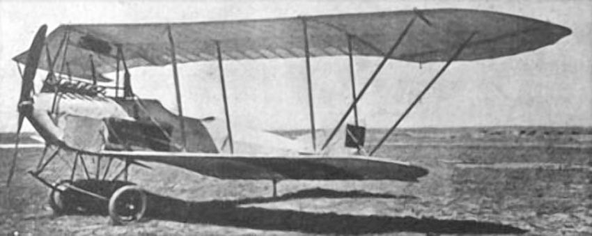
The BM-5 prototype construction started in March 1928 and flown on 27 July that year in Poznań. It had good handling, high stability and spin resistance, which made it a suitable trainer for larger aircraft. The plane was transferred to the military trials, during which some changes were made. During the evaluation flights at the Ławica airport during winter 1929, skis were installed on the aircraft, which proved suitable. A distinguishing feature of all Bartels was an upper wing of a shorter span, because lower and upper wing halves were interchangeable (i.e. the lower wingspan included the width of the fuselage).
BM-5a1
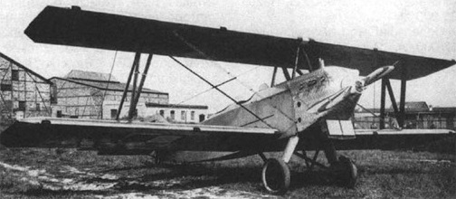
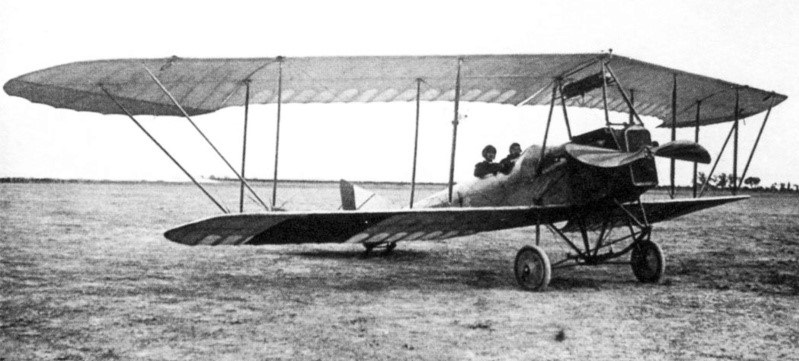
The first prototype was designated BM-5a1 and was fitted with a 220 hp (160 kW) Austro-Daimler inline engine. The second prototype, flown on 15 April 1929, was designated BM-5b1 and was fitted with a 230 hp (170 kW) SPA-6A inline engine. Compared with its predecessor, it was heavier by 60 kg due to a larger supply of fuel. Two BM-5b1 were built. It was refitted in August with a 320 hp (240 kW) Hispano-Suiza 8Fb V-engine and redesignated BM-5c1 (it was meant to utilize engine stores from the Bristol F.2 Fighter) and was flight tested on July 29, 1929. Next 20 aircraft of each type were built: BM-5a2, BM-5b2 and BM-5c2.
Bartel BM-5b
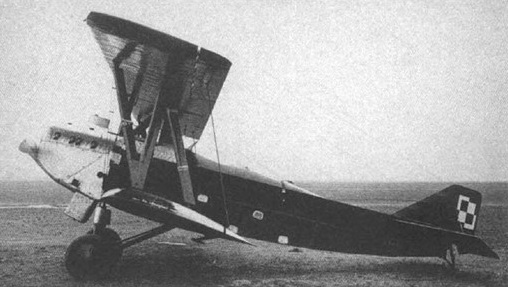
A disadvantage of most BM-5s were old and faulty engines. From all the variants the BM-5a variant was the heaviest and had the worst performance. Several BM-5a burned in a fire in September 1929. For that reason in 1935 one BM-5 was fitted at the PZL works with a 240 hp (180 kW) Wright Whirlwind J-5 radial engine, produced in Poland (in Polish Skoda Works, then Avia). This variant was designated the BM-5d and 20 of BM-5a and BM-5b were next converted to BM-5d.
BM-5d
On March 20, 1929 a contract was signed for series production of 40: 20 version of the VM-5a and 20 versions of BM-5b, with the first five were equipped with AD225 engine, and the next five – SPA. All production aircraft received the military designation BM-5R2 and deliveries were completed in 1930. These aircraft are sometimes called BM-300. Single copies were in training regiments, squadrons and air camps.
BM-5c1
A total of 62 were built.
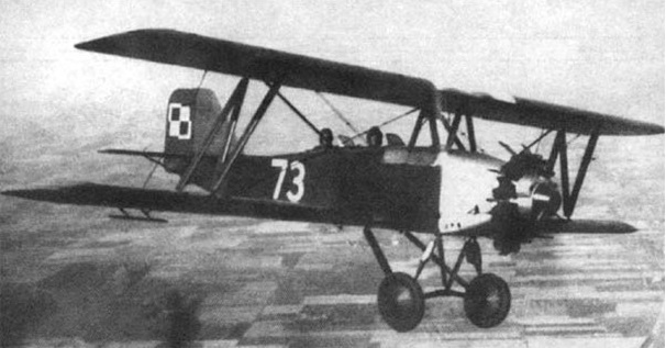
BM-5s were used in the Polish Air Force for training from 1930, in a central pilots’ school in Dęblin. 5 BM-5c’s were used in Naval Air Unit (MDLot) in Puck. Most were written off in the second half of 1930s and replaced with the PWS-26 in April 1938. Some survived until the German invasion of Poland in September 1939. None survived the war.
BM-5c2
Variants:
BM-5a Austro-Daimler 6-cylinder straight engine, water-cooled, 220 hp (160 kW) nominal power Wingspan: 11.2 m Length: 7.81 m Height: 3.18 m Wing area: 31.0 m2. Empty weight: 980-972 kg Useful load: 370-432 kg MTOW: 1350-1395 kg Max speed of 164 kph Cruise: 145 kph Stall: 76-80 kph ROC: 2.6 m / s Ceiling: 3250 m Range: 420-550 km
BM-5a2 Engine: Austro Daimler, 225 hp Wingspan: 11.20 m Length: 7.81 m Height: 3.18 m Wing area: 31.00 sq.m Empty weight: 980 kg Normal takeoff weight: 1350 kg Maximum speed SL: 164 km / h Cruising speed: 145 km / h Practical range: 420 km Rate of climb: 156 m / min Ceiling: 3250 m Crew: 2
BM-5b SPA-6A 6-cylinder straight engine, water-cooled, 230 hp (170 kW) take-off power, 220 hp (160 kW) nominal power Wingspan: 11.2 m Length: 7.81 m Height: 3.18 m Wing area: 31.0 m2 Empty weight: 922-906 kg Useful load: 378 kg MTOW: 1300 kg Max speed: 161 kph Cruise: 145 kph Stall: 70 kph ROC: 3.4 m / s Ceiling: 3075 m Range: 435 km
BM-5c Hispano-Suiza 8Fb 8-cylinder V-engine, water-cooled, 320 hp (240 kW) take-off power, 300 hp (220 kW) nominal power Wingspan: 11.2 m Length: 7.81 m Height: 3.18 m Wing area: 31.0 m2 Empty weight: 947 kg, 383 kg MTOW: 1330 kg Max speed: 172 kph Cruise: 150 kph Stall: 73 kph ROC: 4.5 m / s Ceiling: 4750 m Range: 300-360 km
BM-5d Wright Whirlwind J-5 9-cylinder radial engine, 240 hp (180 kW) take-off power, 220 hp (160 kW) nominal power Wingspan: 11.2 m (36 ft 9 in) Wing area: 31 m² (334 ft²) Length: 7.6 m (24 ft 11 in) Height: 3.18 m (10 ft 5 in) Empty weight: 900 kg (1,980 lb) Loaded weight: 1,290 kg (2,838 lb) Useful load: 390 kg (858 lb) Wing loading: 41.6 kg/m² (8.50 lb/ft²) Power/mass: 140 W/kg (0.085 hp/lb) Maximum speed: 172 km/h (93 knots, 107 mph) Cruise speed: 150 km/h (81 knots, 93 mph) Stall speed: 70 km/h (38 knots, 43 mph) Range: 450 km (243 nm, 280 miles) Service ceiling: 4,000 m (13,100 ft) Rate of climb: 4 m/s (790 ft/s) Crew: 2, student and instructor Armament: None
In 1913, several copies of the Austrian Lohner Pfeilflieger aircraft (later Lohner B.I) were brought to Spain. After reviewing the design of these aircraft from Eduardo Barron (Eduardo Barrón y Ramos de Sotomayor) decided to modify the Pfeilflieger.
As a result, on April 3, 1915, a new lightweight auxiliary aircraft, the Barrón Flecha (arrow), flew into the sky. After successful tests for the Spanish Air Force, six such aircraft were ordered. All of them were built in the workshops of Cuatro Vientos. Several aircraft like the Pfeilflieger were equipped with an Austro-Daimler engine with an output of 80 hp, and the rest received 100-horsepower Mercedes engines.
At the end of 1916, the Hispano Suiza 8A eight-cylinder engine with a power of 140 hp appeared. (103 kW). Eduardo Barron equipped this engine with one Flecha and arranged a demonstration flight for the King of Spain Alfonso XIII.
After receiving royal approval, Barron built 12 aircraft for the Aeronáutica Militar at the Carde and Escoriaza plant in Zaragoza. The military used Flecha until 1919. And Barron based on the Arrow has developed an even more advanced machine – Barron W.
Wingspan: 13.40 m Length: 8.50 m Height: 3.00 m Wing area: 37.50 sq.m Empty weight: 630 kg Max weight: 970 kg Engine: Hispano Suiza 8A, 140 hp Max speed: 115 kph Cruise speed: 95 kph Crew: 2
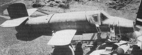
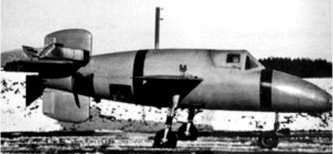
In August, 1944, that the idea of “Natter” (German for Viper) was conceived and four designers, Heinkel, Junkers, Messerschmitt and Bachem, were directed to submit plans. Diplomeur Ingenieur Erich Bachem who made his first appearance with his submission of the BP(Bachem Projekt)20 Natter (Adder). The BP-20 was envisioned as a small lightweight expendable interceptor, capable of destroying any enemy bomber using the least possible weapon expenditure. Dr. Bachem’s design was chosen and in November of that year Natter BP-20 was flown for the first time. Smaller than the Me-163 (span, 13 feet; length, 20 feet, 6 inches) and simpler to build (wooden airframe required only 600 man hours) it looks more like a mock-up than a full-fledged fighter. Because of the short take-off area required it was well suited to close defense of vital targets and pilots required very little training. Launched from a nearly vertical ramp, powered by a Walter rocket unit similar to that used in the Me-163, the initial rate of climb was calculated at 37,000 feet per minute, its top speed at more than 600 miles per hour. A controlled missile until within a mile of its target, the pilot then takes over, jettisons the nose cone exposing 24 Fohn 7.3 caliber rockets which are fired in one salvo. Protected by exceptionally heavy cockpit armor and presenting a small head-on target, the pilot is virtually invulnerable to enemy fire. His principal danger is in take-off and descent. Going into a dive after two minutes or less in the air he bails out and a section of the fuselage containing the rocket unit likewise descends by parachute. It was the first vertical-takeoff fighter ever built and certainly the first where the pilot was expected to bail out on every mission.
That project had its origin in a proposal in 1939 by rocket engineer Dr. Werner von Braun. This proposal was rejected as unworkable by the Reichluftfahrtministerium (RLM-German Air Ministry) but found an enthusiastic supporter in Bachem who tried, and failed, to generate interest in several different proposals for a rocket interceptor along the lines suggested by von Braun. The airframe was comparatively crude, largely of wood construction and was to be built without the use of gluing presses or complex jigs. Most parts could be made in small woodworking shops through Germany, without interfering with the existing needs of the aircraft industry. According to Bachem, only 600 man-hours would be required for the production of one airframe, excluding the rocket motor, which was relatively simple to manufacture when compared to a sophisticated turbojet. This motor was the same basic engine used in the Me-163 Komet interceptor, a Walter 109-509A-1 that used the reaction between two chemicals, T-Stoff (a highly caustic solution of concentrated hydrogen peroxide and a stabilizer) and C-Stoff (a mixture of hydrazine hydrate, methanol alcohol, and water) to provide 3,740 lb (1,700 kg) of thrust. Extra power for lift-off was generated by four 1,102 lb thrust solid-fuel rocket boosters bolted to the rear fuselage giving a combined thrust of 4,800 kgf (47 kN or 10,600 lbf) for 10 seconds.
The short, untapered, stubby wings had no ailerons, lateral control being exercised by differential use of the elevators mounted on a cross-shaped tail augmented by guidel vanes positioned in the exhaust plume of the main rocket. The cockpit was armored and armament consisted of 24 unguided Henschel Hs 217 Föhn 73 mm rockets mounted in tubes in the nose of the aircraft and covered by a nose cone. The cockpit was equipped with only basic instruments, the instrument panel actually serving as the pilot’s frontal armour. The pilot was protected by armour on each side of the seat, and a rear armoured bulkhead at his back separated the cockpit from the fuel tanks, which contained 6gal of a hydrogen peroxide and oxyquinoline stabiliser solution and 41.8gal of 30 per cent hydrazine hydrate solution in methanol. In operation, the Natter would be launched from a 79 ft (24 meter) tower. Guide rails would stabilize the wingtips and lower tailfin until the tower was cleared. (Towards the end of the war, as steel became scarce, the tower was replaced with a simple 29 ft [9 meter] wooden pole with a pair of shortened launch rails bolted to it. There was the need for a solid concrete foundation into which the gantry could be secured, though the wood pole version could be quickly dismantled and removed from a mounting set into such a base.) Controls would be locked during launch. About 10 seconds after launch, the solid-fuel boosters would burn out and be detached by explosive bolts and the controls would become operational. The aircraft’s autopilot would be controlled from the ground by radio; the pilot could assume manual control at any time. The Natter would accelerate upward with a proposed climb rate of 37, 400 ft (11,563 meters) per minute until it reached the altitude of the Allied bomber formations which could range from 20,000 ft to 30,000 ft (6,250 meters to 9,375 meters). The pilot would then take control of the Natter, steer it in close, jettison the nose cone, and fire all 24 of the rockets simultaneously at the bomber. The rocket fuel would be exhausted by now and the pilot was to glide downward to about 4,500 ft(1,400 meters). He would then release his seat harness and fire a ring of explosive bolts to blow off the entire nose section. A parachute would simultaneously deploy from the rear fuselage and the sudden deceleration literally throw the pilot from his seat. The pilot would activate his own parachute after waiting a safe interval to clear the bits of falling Natter. Ground crews recovered the Walter motor to use again but the airframe was now scrap. It was also envisioned that the Natter could be used on the remaining surface fleet with an air defense capability previously denied to ships. Bachem now pulled strings to get his proposal accepted. The strings that he pulled belonged to Reichsführer Heinrich Himmler, head of the Shutzstaffel (SS-Protective Staff). Himmler saw the possibility of establishing a fleet of aircraft beyond the control of the Luftwaffe and the RLM and signed an order for 150 of Bachem’s machines using SS funds. Alarmed, the RLM now approved Bachem’s design and placed their own order for 50 of the aircraft under the designation Ba-349 Natter (Adder). With orders from both the Luftwaffe and the SS Führungshauptamt (Planning Office), Bachem set up a factory to design and build his dream at Waldsee in the Schwarzwald (Black Forest) about 25 miles (40 km) from the Bodensee (Lake Constance). Wind-tunnel models which were built early in the program were shipped off for testing and the only results returned to the Bachem designers were that it would be satisfactory up to speeds of about 685 mph (1,102 km/h). An initial series of 50 Natters was built within three months of the launching of the project, and unpowered gliding trials began in November 1944. The first successful pilotless launch was accomplished on December 22, 1944, with a dummy in the cockpit. A Heinkel He-111 bomber carried one to 18,000 ft (549 meters) and released it. The pilot found the aircraft easy to control. At 3,200 ft (1000 meters), he fired the explosive bolts and the escape sequence worked as designed. A powered vertical launch failed on December 18 because of faulty ground equipment design. On December 22, the aircraft made its first successful launch with the solid fuel boosters only because the Walter motor was not ready. Ten more successful launches followed during the next several months. Early in 1945, the Walter engine arrived and the Natter launched successfully with a complete propulsion system on February 25, 1945, carrying a dummy pilot. The launch proved that the complete flight profile was workable. All went according to plan, including recovery of the pilot dummy and Walter rocket motor. Although Bachem wanted to conduct more pilotless tests, he was ordered to begin full power piloted trials immediately. On February 28, 1945, a volunteer, Oberleutnant Lothar Siebert, attempted the first manned, full power Natter launch. However, the cockpit canopy detached itself at an altitude of 1,650 ft because of improper locking. Siebert was knocked unconscious as the Natter continued to climb to 4,800ft before nosing down and crashing, with fatal consequences. More pilots volunteered to fly and the Bachem team launched three flights in March. Manned flights continued, seven of them, but only 36 of the 200 Natters ordered were completed. Altogether 25 Natters actually flew, though only seven of the flights were piloted, in April 1945 ten Natters were set up at Kirchheim near Stuttgart to await a chance to intercept Allied bombers. However, Allied tanks arrived at the launching site before the bombers appeared, and the Natters were destroyed on their ramps to prevent their capture. French tanks advanced into Waldsee on April 1945 and a great number of spare parts from the Bachem factory were captured. Only a few days before the French arrived, fifteen rocket engines destined for Nattern had been thrown into Lake Waldsee to prevent their capture. The secret was not well kept however and all were later recovered. A B model Natter, with revised armament and an auxiliary cruise chamber in the engine to increase powered endurance from 2.23min to 4.36min, was in the works at the end of the war. Three Ba 349Bs were built before VE Day, but only one was test flown. Only two authentic Nattern survive. One is at the Deutsches Museum in München (Munich), restored in the colors and markings of one of the unmanned test aircraft. The Smithsonian Institution’s National Air and Space Museum in Washington DC has the other Natter which was captured by U. S. forces at the war’s end and shipped it to Freeman Field, Indiana, for analysis. The captured equipment number T2-1 was assigned to the Natter and the US Air Force transferred it to the National Air Museum (now NASM) on May 1, 1949.
Ba 349 Engine: One Walter HWK 509A rocket + 4 solid rocket boosters, 16.7 kN (10,600 lbf) Launch weight: 800 kg (1940 lb) (empty), 2,232 kg (4,920 lb) (full load) Length: 6.02 m (19 ft 9 in) Height: 7 ft 4.5 in Wing span: 3.60 m (11 ft 10 in) Wing area: 51.6 sq.ft Speed: 1,000 km/h (620 mph) Range: 6 min of flight Flying altitude: 14,000 m (46,000 ft) Warhead: 24x 73 mm Hs 217 Föhn rockets or 33x 55 mm R4M rockets
Ba 349A Powerplant: one 1700 kg (3,748 1b) thrust Walter 109 509A 2 liquid fuel rocket motor (of 70 sec power duration) and four 1200 kg (2,646 lb) thrust Schmidding 109 533 solid fuel jettisonable booster rockets (of 10 sec power duration). Max speed: 800 km/h (497 mph) at SL / 560 mph at 16,400ft Service ceiling: 14000 m (45,930 ft) Initial ROC: 11140 m (36,550 ft)/min. Radius of action: 40 km (24.8 miles). Launch Weight: 2200 kg (4,850 lb). Wing span: 3.60 m (11 ft 9.75 in) Length: 6.10 m (20 ft 0 in) Wing area: 2.75 sq.m (29.6 sq.ft) Armament: 24 Fohn 7.3 cm (2.87 in) unguided rocket projectiles in nose.
Ba 349B-1 Engine: One 4,409 lb (2,000 kg) st Walter HWK 509C 1 bi fuel rocket motor, plus (for take off) four 1,102 lb(500kg) or two 2 205 lb (1,000 kg) Solid fuel rockets. Wing span: 13 ft 1.5 in (4.00m). Length: 19 ft 9in (6.02 m). Wing area: 50.59 sq.ft (4.70sq.m) Gross weight: 4,920 lb (2,232 kg). Max endurance: approx 4 min. Crew: 1 Initial ROC: over 37,000 ft (11,280 m)/min. Max speed: 620 mph (1000 kph) at 16,400 ft (5,000 m).
The Royal Canadian Air Force, needed an all weather fighter to defend the vast dominion and after talking with the American and British air staffs decided to write its own specification, issued in October 1946. It called for a fighter having a crew of two, advanced radar, all weather and night equipment, heavy gun armament, the ability, to operate from advanced air¬bases with austere ground equipment and runways only 4,000ft long. Plus a combination of speed, rate of climb and range never before attained in any combat aircraft.
Design of the two-seat all-weather long-range fighter was initiated in October 1946, the Avro Canada team under E. H. Atkin, chief engineer, settled for a long slim fuselage, low unswept wing of quite high aspect ratio, and twin engines on the sides of the fuselage above the wing. The Avro scheme made the engines higher off the ground, but still easy to service and not difficult to change. The steerable nose gear and main legs all had twin wheels. The first of two prototype CF-100 Mk Is (No 18101, FB-D) was flown on 19 January 1950, both of these aircraft being powered by Rolls-Royce Avon RA 3 turbojets, each of 2948kg thrust. Although not designed for speeds over Mach 0.85, it was taken supersonic during a dive by test pilot Janus Żurakowski in December 1952.
It was a low-wing cantilever monoplane of all metal construction, the tail unit incorporating a tailplane and elevators mounted mid-way up the fin. The retractable tricycle landing gear had twin wheels on each unit, and accommodation for two, in tandem, was in a pressurised cockpit. All control surfaces were fully powered. Large airbrakes were fitted above and below the wing ahead of the flaps. Pilot and navigator sat in tandem Martin Baker seats.
CF-100 Mk.1
Successful testing of the prototypes led to an order for 10 unarmed pre-production CF-100 Mk 2s, these being the first examples to be powered by 2722kg / 6,000 lb thrust Orenda 2 turbojets, built by the engine division of Avro Canada. When the first of these CF-100 Mk 2s made its maiden flight, on 20 June 1951, it was the first aircraft that had been completely designed and built in Canada. One of this pre-production batch was equipped as a dual-control trainer, becoming designated CF-100 Mk 2T, and another example from this batch was the first to enter service with the RCAF, on 17 October 1951.
Orders followed for 124 production aircraft designated CF-100 Mk 3 in September 1950, named Canuck by the RCAF, and the first of these entered service soon after a first flight in early September 1952. They differed by having Orenda 8 turbojets of 6,000 lb thrust (of similar output to the Orenda 2s), carried eight 12.7mm Colt-Browning machine-guns in a ventral pack, which could be winched in or out of the fighter as a unit, and were equipped with nose-mounted AN/APC -33 radar. The Mk 3 entered service with No 445 Squadron at North Bay, Ontario, in 1953. A total of 70 of this version was built before production switched to the definitive CF-100 Mk 4, and once the Mk 4 became available in 1954, most of the remaining Mk 3’s were either used at the Operational Training Units or converted to dual control trainers. 50 were converted to CF-100 Mks 3CT and 3DT trainers.
CF-100 Mk.3A
In 1951, in partnership with Hughes Aircraft, Avro Canada completely replanned the CF 100 with the new armament. The tenth CF 100 Mk 2 was chosen as the aircraft to develop the new system, making its maiden flight as the prototype Mk 4 on October 11, 1952, the same day as the first production Mk 3. The nose was longer and fatter, and instead of the APG 33 gunsight radar of the Mk 3 there was a radome for the MG 2 (E4) fire-control radar. The standard Mk 4 retained the gun pack but added wing tip pods each housing either 29 or 30 Mighty Mouse rockets, the same FFAR (folding fin aircraft rocket) of 2.75in calibre as standard on the, USAF interceptors. The Mk 4 had collision course fire control, the new interception method in which the radar and autopilot interlinked to steer the aircraft automatically to launch the rockets in a salvo to pass through a “box” of sky at the same time as the hostile aircraft. It freed interceptors from the need to attack from behind, and in a side on interception gave a much better reflective target for the radar.
The last 54 aircraft were cut from the Mk 3 order, holding production of this model to 70, while orders for the Mk 4 were repeated until they reached the total of 510. It was the RCAFs standard all weather fighter in 1953 59 and continued to serve, into the 1960s after modification to Mk 5 standard. Early Mk 4s were styled Mk.4A and fitted with the Orenda 9 rated at 6,500 lb, and visually distinguished by the free spinning two-blade windmill on the inlet bullet from which alcohol anti icing fluid could be sprayed. The Mk 4B was fitted with the Orenda II of 7,275 lb thrust, and most 4Bs were also fitted with all-rocket armament, the gunpack being replaced by a retractable box containing a further 48 FFARs launched in salvo by hydraulically extending the box briefly into the airstream. A further modification in most 4As and all 4Bs was that the large canopy was blown from a single sheet of Plexiglas.
CF-100 Mk.4B No.445 Sqn RCAF, Marville, France 1957
The first production Mk 4 flew on October 24, 1953. The Mk.4 version was redesignated CF-100 Mk 4A after the introduction of a generally similar CF-100 Mk 4B that differed primarily by having more powerful Orenda 11 turbojets, each of 3300kg thrust.
Unofficially known as the Canuck, the CF-100 Mk 4A was the first CF-l00 to be fitted with AN/APC-40 radar and was powered by the 2948-kg (6,500-lb) thrust Orenda 9 turbojet engine, which was replaced by the slightly more powerful Orenda 11 on the CF-100 Mk 4B model. Armament in both cases took the form of eight 12.7-mm (0.5-in) machine-guns backed-up by 104 70-mm (2.75-in) rockets carried in the distinctive wing-tip pods. Production of CF-100 Mks 4A and 4B totalled 134 and 144 respectively, being followed by the CF-100 Mk 5 production version.
The CF-100 Mk 5, which featured an extended wing span and updated equipment, was lighter for it lack-ed the machine-guns of earlier variants, relying solely on rockets for interception. Aimed entirely at increasing high altitude manoeuvrability, the Mk 5, the first of which flew on October 12, 1955, had just over 3.5ft added on the end of each wing, the new sections having constant chord. Tailplane area was also slightly increased, and among less basic changes was the introduction of a larger wingtip pod housing 52 FFARs, making (with the centreline pack) a maximum of 152. No Mk 5s were built new, the 100 aircraft for inventory being converted while the final 4Bs were still on the assembly line, 53 of which were supplied to Belgium, based at Beauvechain, these being the only CF-100s to be exported.
The first production example flew on 12 October 1955.
CF-100 Mk.5
In addition, a substantial number of CF-100 Mk 4s were up-dated to the later configuration for service with squadrons of the then Royal Canadian Air Force in both Canada and Europe. The CF-100’s operational career as an interceptor came to an end in the early 1960s, but a few aircraft were further modified to act as electronic aggressors in evaluating the performance of Canada’s defences. Known as CF-100 Mk 5C and CF-100 Mk 5D aircraft, these were finally retired by No. 414 Squadron in late 1981.
On November 4, 1956, No 445 Squadron brought its Mk 4Bs to Europe to add all¬-weather defence to AAME (Allied Air Forces Central Europe), and until 1962 four RCAF squadrons of 4Bs and 5s operated from the Gros Tenquin/ Marville, / Zweibrücken / Baden Söllin¬gen complex as the all weather com¬ponent of the 1st Air Division. So reliable were the Canadian fighters¬ ¬that the Belgian Air Force purchased 53 ex RCAF Mk 5s and took delivery from December 1957. By this time all CF 100s in front line service had green/grey camouflage, the Belgians merely changing the national markings. Though the added wing sections caused structural problems at high indicated airspeeds the Mk 5 remained an adequate all weather platform well into the 1960s.
The Avro CF-100 “Canuck” was the RCAF’s second operational jet fighter replacing the de Havilland Vampire. They patrolled the skies over North America and Western Europe from 1953-1981. The aircraft last served with No. 414 “Black Knight” squadron (electronic warfare unit) at North Bay, as a Mark 5D ECM (electronic counter measures aircraft).
A total of 692 aircraft were produced in the different variants, and the CF-100 was world’s first straight-wing combat aircraft to exceed Mach 1 (in a dive, 18 December 1952). Many innovations in radar and quick-change weapons were developed on the CF-100, and some of its design features were incorporated in the Avro Arrow.
A. V. Roe Canada CF-100 Mk.1 All-weather fighter Engines: 2 x 6,500 lb. thrust Avro Orenda 9 turbojets. Wingspan: 58 ft 5 in Length: 54 ft. 4 in Loaded weight: 34,000 lb. Max. speed: over 650 m.p.h. Max. range: 2,000 miles. Armament: 132x.2.75 in. rockets. In retractable pack under fuselage and wing-tip containers. Crew: 2
CF-100 Mk 3D dual trainer Engines: Two Orenda 8, 6000 lb thrust axial flow gas turbine Maximum speed: Mach .85 Empty weight: 23,000 lb (10 432 kg) Maximum weight: 34,000 lb (15,436 kg) Span: 57 ft 6 in (17.5 m) over tip tanks Length: 52 ft 3 in (15.9 m) Height: 14 ft 6 in (4.4 m)
CF-100 Mk 4 Engines: 2 x 2948kg thrust Orenda 9
CF-100 Mk 5 Engines: 2 x turbo-jet Orenda 11 or 14, 32.3kN, 3300-kg (7, 275-lb) Max take-off weight: 16330 kg (36,000 lb) Empty weight: 10478 kg / 23100 lb Wingspan: 18.54 m (60 ft 10 in) Length: 16.48 m / 54 ft 1 in Height: 4.74 m / 16 ft 7 in Wing area: 54.9 sq.m / 590.94 sq ft Wheel track: 10 ft 2 in Wheelbase: 18 ft 1 in Maximum speed 1046 km/h (650 mph) at 3050 m (10,000 ft) Initial climb rate 2591 m (8,500 ft) per minute Service ceiling: 16460 m / 54000 ft Range w/max.fuel: 3220 km / 2001 miles Range w/max.payload: 2072 km / 1288 miles Combat radius 1046 km (650 miles) Armament: 29 x 70mm missiles in each of wing containers Crew: 2