Boeing 737 / P-8 Poseidon / C-40 / T-43 / E-7

Boeing 737-500

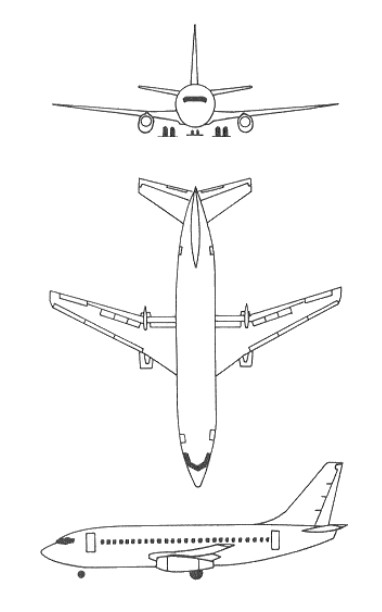
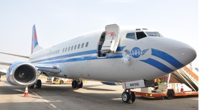
As originally conceived, the Boeing 737 series 100 could accommodate sixty to eighty-five passengers but after talks with Lufthansa this was increased to around 100 seats. The newly designed wing was required to give good lift and have excellent low speed characteristics for short-field operations, around 870nm. The engines selected were two Pratt & Whitney JT8D-1 turbofans, each of 14,000 pounds thrust, but following negotiations with Lufthansa the more powerful JT8D-7 turbofan was chosen for it could maintain the same thrust at higher ambient temperatures. The aircraft has almost the same fuselage cross-section as the longer 707 and 727, designed so that maximum use could be made of 727 tooling and components to keep initial costs low. The aircraft is powered by the JT8D turbofan engine developed for the 727, and has the 727’s high-lift system. The 737 utilised the same nose and fuselage section as the 727. Wing sweepback on the 737 is 25 degrees. The prototype 737-100 first flew on 9 April 1967 and was so successful that by 15 December 1967 FAA certification was complete and Lufthansa took delivery of their first machine on 28 December 1967. They made their first scheduled 737 passenger flight on 10 February 1968. Only 30 of the -100 series were built.

Boeing 737 Article

United Airlines launched the 737-200 with a 1.82m fuselage stretch, first flown on 8 August 1967. The -200 was added to the 737-100 type certificate on 21 December 1967, and first delivery to United Air Lines on 29 December 1967.

In production from 1966 to 1988 (1114 aircraft), the 737-100 offered 85 – 90 seats and a maximum take-off weight of 110,000 lb initially with two JT8D-7 of 14,000 lb thrust. The Dash 9 engine of 14,500-lb thrust was also available. The -200 Series offered a maximum take-off weight of 115,500 lb, rising to 128,100 lb for the Advanced version. Engine types available were the Dash 7, the 9A with 14,500 lb, the l5A with 15,500 lb and the l7A with 16,000 lb thrust.

The T-43As being navigation trainers and the C-40A being the 737-NG model 700. Boeing has delivered the 19th and final T-43 Navigator Trainer aircraft to the USAF’s Air Training Command in 1974. The aircraft, a military derivative of the 737-200 twinjet, flew to Mather AFB, Sacramento, California. Boeing says the T-43 programme was completed on schedule and within the $81.7m contract which Boeing won in May 1971. Deliveries began in 1973.

In 1978 British Airways ordered 19 737-200 Advanced, which entered service in February 1980. More followed in 1980/1981, and another batch of 16 was ordered in Autumn 1983, with the last delivered in spring 1985, bringing the fleet to 44 aircraft. In October 1988 new orders were announced, which included firm placements for 24 737s, with built in flexibility to choose from the 737-300, or the new -400 or -500 models. British Airways eventually opted for the larger -400. Eleven options were also included and soon taken up, with the new type introduced into service in October 1991.

A maritime surveillance version of the 737-200, the Surveiller is equipped with a Motorola side-looking modular multi-mission radar (SLAMMR), linked to two 5m-long antennae mounted on each side of the upper rear fuselage. The radar has a typical range of 185km on each side of the aircraft at a patrol height of 9,150m (30,000ft). B737-219 is a quick change variant, from freight to passengers.

Boeing 737-2A6 ZK-NEE

The last of 1,114 Boeing 737-200s (and 30 737-100s) was delivered in August 1988. The total includes 19 T-43A navigation trainers for US Air Force (subsequently redesignated CT-43A) and three Surveillers for Indonesian Air Force.

In the end it was the rather noisy JT8D-15 engines that prompted Boeing to look for a replacement for the 737-200 advanced. Already operators throughout the world were turning to Europe for replacement jets such as Airbus and the Hawker Siddeley 146 both of which offered quieter and more fuel efficient engines. Initial design analysis showed that the new high by-pass ratio turbofans were all too big and Boeing prompted the development of the smaller diameter CFM-56 which offered 20,000 lbs thrust. The new aircraft retained about 70 percent commonality with the previous 737-200. The biggest changes, apart from the engines, were the increased fuselage length and minor changes to the wing tip. The larger turbofans did need new pylons and Boeing, with the help of CFM, redesigned the arrangement of auxiliary units inside the pod so that instead of fitting them symmetrically around the engine they were arranged on the sides giving the 737-300 engine pods that characteristic squashed look.

Production go-ahead for the Series 300 was given in March 1981 at the first flew on 24 February 1984, the 737-300 powered by CFM56-3 engines was FAA certified on 14 November 1984 and Boeing made the first delivery to USAir on 28 November 1984.

Boeing 737-341 PP-VOO

On 8 January 1989, a newly-delivered 737-400 belonging to British Midland crashed onto the M1 motorway at Kegworth, UK, during an emergency landing attempt, killing 32 people. The crew believed that an engine was on fire, but incorrectly wired cockpit systems may have given them false information.

Approval for 120-minute ETOPS given November 1986, but withdrawn July 1989 due to concerns related to operation in heavy rain and hail; approval restored 14 September 1990.
Commonwealth of Independent States Interstate Aviation Committee certified the Boeing 737 family with P&W or CFM engines 18 January 1993 and the first delivery for Russian Federation and Associated States (CIS) registration (737-300 to National State Aviacompany Turkmenistan) was on 12 November 1992.
A 737-300 for Ansett Worldwide (and subsequent lease to British Midland Airways) rolled out at Renton on 19 February 1990 (as 1,833rd 737); 737 orders passed 3,000 when Southwest Airlines ordered 34 in third quarter 1992.
The 2,500th 737 rolled out 16 June 1993; 3,000th Classic’ 737, a 737-400 for Alaska Airlines (N793AS) first flew on 16 January 1998. Production of Classic’ averaged 9.5 per month during 1998.

Further developments at Boeing resulted in the even larger 737-400 which was first announced in June 1986 and the first example flew on 19 February 1988. Considerably longer than the 737-300 (3.05 metres). Announced June 1986, the first rolled out on 26 January 1988 and first flew on 19 February 1988.

Certified for up to 188 passengers on 2 September 1988, the first delivery (to Piedmont Airlines) was on 15 September 1988.

A high gross weight structure variant rolled out on 23 December 1988; certified by the FAA and delivered to first customer 21 March 1989. ETOPS approval was granted on 14 September 1990. Russian Federation and Associated States (CIS) certification with CFM engines was on 18 January 1993, as for the 737-300.

Initially known as 737-1000 and then announced as the 737-500 on 20 May 1987, the -500 first flew on 20 June 1989; certified 12 February 1990 after 375 hour test programme; and first delivery (to Southwest Airlines) 28 February 1990. ETOPS approval was given on 14 September 1990. Russian Federation and Associated States (CIS) certification with CFM engines was given on 18 January 1993, as for 737-300 and -400. Smallest, and exactly the same size as the original 737-200, is the turbofan powered 737-500. Capable of carrying 108 passengers in comfort, the 737-500 consumes up to 20 percent less fuel per seat-mile than a comparably loaded 737-200. The 737-500 went into regular service in March 1990 with SouthwestAirlines.

Boeing 737s up to and including -500 are known as Classic' series to differentiate them from ‘Next-Generation’ variants beginning at -600.

United Nigeria – B737-500 – NAF 916

In 1996 the Lufthansa fleet included 89 Boeing 737 and 26 Boeing 747s.

The 737-700 first flew on 9 February 1997, was delivered to Southwest and entered service on 18 January 1998.

Boeing 737-700BBJ M53-01

In 2003, the Australian Defence Force’s first 737-700 “Wedgetail” aircraft had installed a multi-role electronically scanned array antenna, 35.5 ft long and weighing over 3 tonnes, the antenna was described a “the critical sensor aboard the aircraft”. The Royal Australian Air Force Wedgetail airborne early warning and control (AEW&C) aircraft entered service in 2009. Six Boeing 737 NGs were modified to accommodate sophisticated mission systems and radars that will increase Australia’s surveillance and air combat capability, provide air defence support for the naval fleet, and assist in civil operations such as border protection and search and rescue. The Wedgetail AEW&C aircraft were operated by No 2 Squadron from RAAF Base Williamtown, near Newcastle.

The first two Wedgetails were modified in the United States of America, with the remaining four modified at RAAF Base Amberley, near Brisbane.

Boeing E-7A Wedgetail Article

In February 2006 Boeing delivered the 5000th 737, a 730-700 for Southwest Airlines and 38 years after the first example was delivered. At the time of handover 541 operators were flying over 4100 737s and total sales exceeded 6150.

In January 2007 the first 737-700ER was rolled out, this available in normal airliner form or as in 48-seat all business class configuration with a maximum range of 5510 nm / 10,200 km if fitted with maximum fuel.

The B737-800, essentially a stretched version of the earlier B737-400 seating up to 189 passengers, earned its type certification from the FAA on 13 March 1998. The 737-800NG was launched by Boeing on 5 September 1994. The first delivery of the type was to Hapag-Lloyd on 22 April 1998. Boeing announced on 18 February 2000 that it would offer the blended winglet version of the B737-800NG to customers – a new, advanced technology winglet that has become a standard option. First deliveries of the winglet jet commenced in May 2001. The winglets can be retrofitted and, because of commonality through the 737 range, the blended winglet will be an option for other models that have the B737-800 wing, including the B737-700C/QC and the B737-900. A winglet-equipped 737 is able to fly further, burn less fuel and carry additional fuel than one without winglets. Each winglet is 2.5m long and 1.2m in width at the base, narrowing to approximately 0.6m at the tip. They add approximately 1.5m to the airplane’s total wingspan taking it to 35.8m (all next-generation 737 models have the same wingspan of 34.3m). Each winglet weighs about 60 kg and the overall increase is about 170 kg. Structural modifications to accommodate the winglet include strengthening of the wing’s centre section.

Boeing 737-800

On 26 July 1993 Boeing delivered the 2000th 737NG family example – a 737-700 to Southwest Airlines, eight years after the first one was delivered to the same airline. Total 737NG orders were about 3400, eclipsing the combined total of the first two 737 generations.

The B737-BBJ is a high performance derivative combining the fuselage of the 737-700, strengthened in the aft section, with the centre-section, wing and landing gear of the 737-800. The 737-BBJ is operated by the USAF as the C-40C.
The BBJ combines the fuselage of the Boeing 737-700 aircraft with a strengthened aft section, and the centre-section, wing and landing gear of the 737-800 aircraft. Winglets are standard, affording 5 to 7 per cent reduction in cruise drag, resulting in 4 to 5 per cent increase in range. The BBJ features the same panel as the Boeing 777 and also adds a heads-up display. A variety of fuel tank configurations allow the BBJ to have a more than 6,000 nm range. With a customized interior, some of which feature a conference room and a gymnasium, the BBJ approaches a $50 million total acquisition cost.
Increased fuel capacity is provided by the installation of between three and nine auxiliary tanks in the underfloor baggage holds, providing a maximum range of 6200 nm / 11,485 km.

With the minimum number of three auxiliary tanks installed, range is reduced to 5025 nm / 9310 km but payload increases, allowing about 50 passengers to be carried with full fuel. The first BBJ flew on 4 September 1998, joint FAA/JAA certification was awarded the following month and the first delivery was made in November 1998 to General Electric. The 100th 737-based BBJ – for the Indian Government – flew in November 2006.

A stretched version (19 feet longer) of the original BBJ, the BBJ2 offers 25% more cabin space and 100% more baggage space. First delivery of the larger Boeing Business Jet was in early 2001.
Two Boeing 737 BBJ (Boeing Business Jet) special purpose aircraft are operated by the Royal Australian Air Force’s No 34 Squadron, based at Defence Establishment Fairbairn in Canberra. Both BBJs are permanently converted to VIP configuration, comprising two conference tables and seating for 30 passengers. The BBJs joined the VIP fleet in July 2002.
The 737-900 first flew on 3 August 2000, from Boeing Field. The 900 retains the same wing and engines (CFM56-7s) as the 600, 700, and 800 models. Two fuselage plugs, ahead and aft of the wing box increase the fuselage length by 8ft 8in (2.6m) over that of the 800, for 177 passengers in a two-class configuration, 15 more than the 800. Because of emergency exit requirements, the maximum seating number of 189 is the same as for the 800. Two aircraft were used for FAA and JAA certification. The launch customer being Alaska Airlines with an order for ten placed in November 1997.

Boeing 737-900

On 5 September 1993 the 180-215 seat 737-900ER recorded its maiden flight. Boeing delivered the first 737-900ER to Indonesia’s Lion Air on 27 April 2007. The airline had 60 on order. By June 2007 Boeing had received 7000 orders for all 737 models.

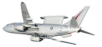
The P-8A Poseidon for the US Navy is the third military derivative of the 737NG airliner after the 737-700BBJ based C-40 clipper cargo and personnel transport and the 737 AEW&C Wedgetail/Peace Eagle.
Chosen by the Navy in 2004 to replace the bulk of its P-3C Orions, the airframe is based on the 737-800 mated with the strengthened wings of the 737-900. The P-8A is powered by two 27,300 lb (122kN) thrust CFM56-7E engines fitted with 180kVa generators. Boeing has changed 75% of the –800s primary structure maily through stronger gauge materials for the expected flight loads. Other changes include a refuelling receptacle in the forward upper fuselage, an integral fuel tank in the aft third of the fuselage, and an internal weapons bay. The weapons bay has five hard points each rated for 650 kg, and two hard points on each wing, outboard of the engines are rated for 1360 kg, and two hard points in tandem on the centre forward fuselage are rated for 650 kg. Raked wingtips are developed from those of the 767-400.

Boeing 737 RAT55

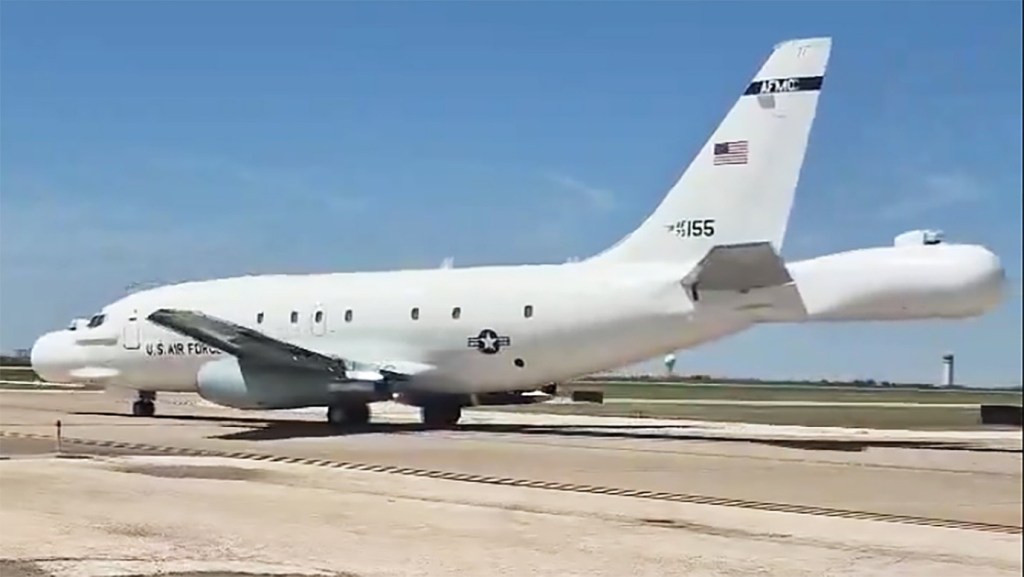
The “RAT” in the name stands for Radar Airborne Testbed, while the “55” refers to the last two digits in its tail number. RAT55 spends most of its flying life in the vast and remote range complexes that span South-Central California and Southern Nevada. The aircraft seems to live at the high-security Tonopah Test Range Airport (TTR) and spends time in the skies near Area 51 and Edwards Air Force Base. While the one-off NT-43A has ventured beyond its usual protected operational confines — it needs major servicing just like any other 737 — usually these trips seem to be planned to expose the aircraft to minimal public eyeballs. That is clearly no longer the goal.

RAT55 is critical to the development and sustainment of America’s aerial stealth technology. Simply put, RAT55 uses its two huge radar arrays — one front and one back — to take fine measurements of the radar signatures of stealthy aircraft while flying through the air near them. It does this to validate low-observable designs and skin treatments. It also has electro-optical/infrared capabilities above its radomes and can be fitted with dorsal fairings for other systems. While there are facilities on the ground that can take similar measurements of aircraft flying through the air, doing it from another specially-equipped aircraft in the air allows the target to be measured from every angle, including from overhead aspects, and continuously.

Even when B-2 Spirits come out of depot maintenance, they usually spend time in the sky with RAT55 to validate that the work done fits established design goals and parameters. That is the most visible of the NT-43A’s work, but the aircraft is also involved with the most advanced and secretive stealth aircraft development programs in the Pentagon’s portfolio, many of which we don’t know about and likely never will.

Gallery

737-100
Engines: 2 x JT8D-7, 14,000 lb thrust.
Length: 90 ft 7 in (27.6m)
Wingspan: 93 ft
Height: 37.07ft (11.30m)
MTOW: 110,000 kg.
Empty Weight: 61,994lbs (28,120kg)
Maximum Speed: 544mph (876kmh; 473kts)
Pax cap: 85-90
Ceiling: 30,000 ft
Range: 1,840 mls
Engines: 2 x JT8D-9, 14,500 lb thrust

737-219
MTOW: 53,070 kg

737 297

737-2Y5
Engines: 2 x JT87D-15A, 15,000 lb thrust
MTOW: 56,600 kg
Pax cap: 100

737-300QC
MAUW: 63,277 kg
Capacity: 142 pax or 17,000 kg cargo

737 713C

737-33R
Engines: 2 x CFM-3C-1 turbofan, 20,000 lb
Wingspan: 28.9m
MTOW: 62.82 tonne
Vne: 566 kts
Max Mach: 0.82

737-37Q
Engines: 2 x GE CFM56-3C-1 turbofans, 22,000 lb
MTOW: 62.82 tonne
MLW: 32.722 tonne

737-4L7
Engines: 2 x GE CFM56-3C-1 turbofans, 23,500 lb
MTOW: 68,000 kg
MLW: 56,200 kg
Fuel cap: 19,000 kg
Length: 115 ft 7 in (35.22m)

737-600
Engines: 2 x GE CFM56-7B turbofans
Seats: 110-132
Range: 3000+ nm
Wing area: 1340 sq.ft
Fuel cap: 26,136 lt
Length: 31.24m

737-700
Engines: 2 x CFM 56-7, 24,000 lb
Wing span: 34.32m
Wing area: 1340 sq.ft.
Length: 33.63m
MTOW: 70,080 kg
Empty wt: 37,971 kg
Zero fuel wt: 54,657 kg
Fuel cap: 26,136 lt
Pax cap: 126-149

737-800
Engines: 2 x CFM56-7B24 (24,000 lb)
MTOW: 74,990 kg (165,325 lb)
Empty wt: 41,554kg (91,610 lb)
Max ldg wt: 66315 kg (144,000 lb)
Fuel cap: 20800 kg
Max cruise: 0.82 mach
Max cruise alt: 41,000 ft
Wing span: 33.41m (112 ft 7 in)
Wing area: 1345.5 sq.ft (125 sq.m)
Fuel cap: 26,025 lt (51,562 lb)
Max payload range: 1900 nm
Pax cap: 162-189
Length: 39.47m (129 ft 6 in)
Height: 12.55m (41 ft 2 in)
T/O dist: 7400 ft (2256m)
Ldg dist: 5250 ft (1600m)

737-8Q8
Engines: 2

Boeing 737 MAX 8
Length: 129 ft 6 in (39.47 m)
Height: 40 ft 4 in (12.29 m)
Cabin Width: 139 in (3.53 m)
Max Payload: 46037 lbs (20882 kg)
Range: 3,800nm (7000km)
Maximum seating: 178

737-900
Engines: 2 x CFM56-7
Length: 138 ft 2 in (42.1m)
Wing area: 1340 sq.ft
Fuel cap: 26,136 lt
Pax cap:177-189

Boeing 737 BBJ (Boeing Business Jet)
Role: Special purpose passenger and VIP transport
Crew: Two pilots and up to four crew attendants
Engines: Two CFM International CFM56-7 turbofans (118.4kN (27,300 lbs) each)
Length: 33.6m
Height: 12.5m
Wingspan: 35.8m (including winglets)
Max take-off weight: 77,565kg
Max landing weight: 60,781kg
Gross weight: 171,000 lbs
Empty weight: 94,570 lbs
Speed: 630km/h normal operations
Range: 11,390km
Ceiling: 41,000 feet
Accommodation: 30 passengers in VIP configuration

BBJ2
Engines: two 26,400 lb. CFM International CFM 56-7 turbofans
Seats: 63
Gross weight: 174,200 lbs
Empty weight: 100,815 lbs
Max cruise: Mach 0.82
Long-range cruise: Mach 0.79
Range: 4,935-6,200 nm
Ceiling: 41,000 ft

CT-43 / T-43A
Engines: 2 x Pratt & Whitney JT8D-9A turbofans. 14,500 lbs thrust
Wingspan: 92.85ft (28.30m)
Length: 100.07ft (30.5m)
Height: 37.07ft (11.30m)
Empty Weight: 61,050lbs (27,692kg)
Maximum Take-Off Weight: 128,100lbs (58,105kg)
Maximum Speed: 586mph (943kmh; 509kts)
Maximum Range: 2,187miles (3,520km)
Rate-of-Climb: 3,760ft/min (1,146m/min)
Service Ceiling: 36,745ft (11,200m)
Accommodation: 5

Boeing 737 NG Wedgetail AEW&C
Role: Airborne early warning and control
Crew: Pilot, co-pilot and airborne electronics analysts and mission specialists (10 mission consoles)
Engines: Two CFM International CFM56-7 turbofans (118.4kN (27,300 lb) thrust each)
Length: 33.6 m
Height: 12.6 m
Wingspan: 34.3 m
Maximum take-off weight: 77,565 kg
Maximum landing weight: 60,782 kg
Maximum speed: 870 km/h
Cruise speed: 760 km/h
Endurance: 10 hours (without air-to-air refuelling)
Ceiling: 12,500 m (41,000 feet)
Equipment:
Multi-role electronically scanned array (MESA) radar with range in excess of 400 km
Electronic warfare self-protection measures including directed infra-red counter-measures , chaff and flares
Communication systems including HF, VHF, UHF, Link-11, Link-16, UHF SATCOM and ICS

Boeing 299 / B-17 Flying Fortress / B-40 / C-108 / F-9

B-17G

Designed to a US requirement for a four-engine bomber capable of long distance travel with a full 2,000lb bombload and reach speeds between 200 and 250 miles per hour. The result was the Boeing Model 229 which first flew in 1934, though was later lost to pilot error. Nevertheless, the US Army Air Corps pursued the design with an order for further developmental models fitted with differing powerplants. Early B-17 models were mostly developmental production variants that included the additions of seal-sealing fuel tanks, better armor protection and a redesigned tail.

America’s USAAC had been a little ahead of Britain in specifying their need for a four engined bomber, and the prototype Boeing Model 299 / XB 17 designed to meet this requirement flew for the first time on 28 July 1935. Powered by four 750 hp Pratt & Whitney Hornet engines, the prototype crashed three months later at Wright Field when the control locks were inadvertently left engaged before takeoff.

Boeing B-17 Article

A pre production batch of 13 Y1B 17s was bought for evaluation.

It was not until 1938 that the USAAC was able to place an order for 39 production B-17B, the last of this batch entering service in March 1940. These were the first B-17 production aircraft to be equipped with turbocharged Wright Cyclone engines, providing a higher maximum speed and much increased service ceiling.

Of the B-17C which followed, a batch of 20 were supplied to the RAF (designated Fortress I) and used operationally in Europe for evaluation, leading to improved B-17D and B-17E aircraft with self-sealing fuel tanks and revised armour and armament.

The Royal Air Force used them to bomb the German naval base at Wilhelmshaven on July 8th, 1941, marking the B 17’s first hostile action.

In late Summer of 1941, Great Britain bought 20 of the B-17C bombers recently produced by the USA, but the RAF had nothing but bad experiences with them. The B-17C’s first war deployment was on Monday 8 September 1941, when they attacked several targets along the Norwegian coast from from close to 20,000ft / 9000m. But the Germans received radar warning of their presence and sent out Me 109s from 77 Sqn, 13th Fighter Wing (based on Stavanger), which shot down 2 Fortress Is and seriously damaged three. After other fiascos with the B-17C, British Bomber Command concluded that they were completely unsafe, ineffective and unsuitable for use in any serious missions.

Following an extensive redesign, to increase armour and armament, new versions were introduced and were widely used by the Americans, both in Europe and the Pacific.

Y1B-17

The initial definitive Flying Fortress model would arrive with 512 examples of the B-17E model which were the first to incorporated the twin .50 caliber tail armament for defense.

Many changes were made as a result of combat experience first by the RAF and then by the USAAF in Europe. Even the B 17E , armed with one 7.62mm and 12 12.7mm machine-guns for defence and able to carry a maximum 7,983kg of bombs, was given a mauling by the Luftwaffe when it first ventured over Europe in daylight: but the Americans stood by their beliefs in the effectiveness of day bombing added still more guns, learned new tactics and eventually made possible the crushing round the clock bomber offensive. This model was followed by the similar B-17F models of which 3,405 were produced.

A further modification programme, this time to improve the bomber’s ability to repel air attacks from the front, produced the B17G with its twin-gun ‘chin’ turret which you can see clearly on this example.

Most extensively built variant was the B-17G (8,680), built by Douglas (2,395) and Lockheed Vega (2,250) as well as at the Boeing plant, Seattle (4,035). The B 17G model, the seventh variation of the original design, was equipped Pratt & Whitney R-1820-97 radial engines with super-chargers that allowed the airplane to cruise at 35,000 feet at a maximum speed of 285 miles per hour. It also carried up to thirteen .50 caliber machine guns and 6,000 pounds of bombs. The addition of a chin turret below the nose (containing two 12.7mm machine-guns) provided better defence against the head-on attacks. U.S.forces used it primarily for high level daylight bombing over Europe. The formidable machine gun placement enabled B 17s to develop a highly effective defensive tactical formation. Production of the B-17G started in July 1943.

Flying the Boeing B-17 Flying Fortress

B-17G manufactured after January 1944 were no longer given a camouflage coating because they were lighter and faster without it

The bombardier sat on a type of swiveling stool with a Norden Bombsight before him. The navigator sat off-set to his rear at a small map-filled desk. Both were supplied with defensive .50 caliber machine guns with the Bendix chin turret under the bombardiers control in the G model and onwards. Access to the nose was accomplished through a smallish passage way underneath the main flight deck.

The pilot and co-pilot sat on the flight deck above and behind the navigator’s position with the pilot to the left and his copilot to the right with both offered equal control access and views of all four of the engines. To their rear was the top gunners position with a catwalk crossing between the payload in the bomb bay. Once past the bomb bay, the radio operators station and his equipment was apparent. The radio operator was also afforded a table and seating along with his communications equipment. Access to the belly turret was available following this area, which further opened up to the staggered waist gunner positions which might or might not have been covered by plexiglass depending on the model.

On 1 July 1942 the first heavy bomber of the American 8th Army Air Force laned in Britain by the North Atlantic route. B-17E “Jarring Jenny” landed at Prestwick airfield, Scotland,

The B-17 flew the 8th Air Force’s first combat mission out of England in August 1942. At 3:20pm on Monday 17 August 1942, 12 B-17E of the 97th Bomber Group (US 8th Air Force) took off on their first mission over Europe, flying with four RAF Spitfire squadrons to provide them cover. US Brigadier General Ira Eaker flew with them, in the plane of the Group Commander, known as ‘Yankee Doodle’. The bombers target was Sotteville-les-Rouen on the left bank of the Seine, site of a railway switch yard crucial to the supplying of Le Harve. The Flying Fortresses released their 166 ton bombload from an altitude of over 22,000 ft. all the bombers returned to base.

The British were skeptical about daylight bombing, but the American strategy was made possible by the ruggedness built into high-flying bombers like the B-17 and by the deadly accuracy of the Norden bombsight. Used as the spearhead of the U.S. Army Air Force’s attacks in Europe, the aircraft also saw combat duty in all theaters of war. Three days after Pearl Harbor, the Japanese convoys en route to Luzon in the Philippines were met by Flying Fortresses.

They flew high in huge formations, protecting each other with cross fire, and dropped 640,036 tons of bombs in Europe for a loss of 4,750 aircraft.

Special variants included the B-40 with up to 30 machine-guns/cannons, which was intended as a B-17 escort, but proved to be an operational failure; BQ-7 pilotless aircraft packed with explosives to be deployed against German targets by radio control, which failed due to unreliable control equipment; CB-17 and C-108 transports; and F-9 long-range B-17 equipped to serve as an air-sea rescue aircraft and able to deploy a lifeboat carried beneath the fuselage.

The YB-40 escort fighter variant airframe and engines were typical B-17 but the armament was 31 guns. The largest was a 40mm faired into the radio hatch. In each waist position was a 20mm cannon plus two 0.5in machine guns. A four-gun turret was in the nose and another in the tail. The upper turret had four more 0.5in, the ball turret two. There were 10 more 0.5in machine guns in various locations.

YB-40

Boeing XB-40 Escort Fortress Article

At the height of production Boeing’s Seattle plant alone produced a completed aircraft every ninety minutes. A total of 12,731 built by Boeing, Douglas, and Lockheed Vega of which just over two-hundred were supplied to the RAF.

B-17 “Memphis Belle” would be stored at Altus AAF after public relations tour

RAF forces took several B-17 models with their applied “Fortress 1”, “Fortress 2” and “Fortress 3” designations, utilizing some in the electronic countermeasures role. Reconnaissance variants appeared with the US Army Air Corps, US Navy and US Coast Guard as well, each with differing designations shown below.

The B-17 Flying Fortress accounted for over 290,000 sorties with 640,000 tons of ordnance dropped during World War Two.

The German 200th Bomber Wing, KG200, carried out special transport missions using captured US B-24 Liberator and B-17 Flying Fortress which the Germans called by the code name Dornier Do 200.

Versions of the wartime Flying Fortress were still in service in 1955 include lhe U.S.A.F.’s QB-17G drone, SB-17 with an airborne lifeboat and CB-17G V.I.P. transport; and the U.S. Navy’s PB-1G air-sea rescue and PB-1W radar early-warning aircraft. All have four Wright R-1820-97 piston engines.

Boeing QB-17G Fortress
QB-17 testing guided missiles

US Navy and Coast Guard rescue version are similar to the SB-17G is designated PB-1G.

SB-17G

In New Mexico in 1950, Project Cirrus involved seeding rain clouds with dry ice from a B-17.

Project Cirrus
Project Cirrus
Project Cirrus
USAF Research & Development Command B-17G testbed with 3500hp Wright R-3350

Replica:
Bally B-17

Gallery

Allison Engines Testbed Gallery

XB-17
Engines: 4 x P&W Hornet, 750 hp
Wingspan: 103 ft 9 in
Length: 68 ft 9 in
Take-off weight: 43,000 lb
Bombload: 2570 lb
Loaded range: 2000 mi at 204 mph

STANDARD DATA:
Gross weight: 49,650 lb
Empty weight: 30,620 lb
Fuel capacity: 1,700 Usgals
Engines: four 1,200 hp Wright Cyclone radials.
Top speed: 323 mph
Cruise speed: 250 mph
Climb to 25,000 ft.: 41 min
Range: 3,400 nm
Ceiling: 37,000 ft.

B-17
Engines: 4 x Wright R 1820-97, 1,200 hp, 885kW
Length 73.9 ft. (22.5 m)
Height: 5.8 m / 19 ft 0 in
Wing span: 103 ft 8 in (31.6 m)
Wing area: 141.9 sq.m / 1527.40 sq ft
Weight empty 32,250 lb. (14,630 kg)
Max. bomb load: 9,600 lb (4,350 kg)
Max. Speed 317 mph (510 kph)
Cruise speed: 250 km/h / 155 mph
Range 2,000 miles (3,220 km) with 4,000 lb. of bombs
Ceiling: 10700 m / 35100 ft
Crew: 10
Armament: Up to thirteen 0.30 and 0.50 in. machine guns

B-17E
Engine: 4 x Wright R-1850-65 Cyclone, 1200 hp
Wing span: 103 ft 9 in (31.62 m)
Length: 73 ft 10 in (22.5 m)
Height: 19 ft 2 in (5.84 m)
Engines: 4 x Wright, 1200 hp
Max TO wt: 53,000 lb (24,040 kg)
Max level speed: 275 kts / 317 mph / 510 kph
Service ceiling: 36581 ft / 11150 m
Range: 2592 nm / 4800 km
Crew: 9
Armament: 13x MG 12,7mm, 7985 kg Bomb

B 17G
Engines: 4 x Wright Cyclone R-1820-97, 1,200 hp
Wing span: 103 ft. 9.5 in / 31.62m
Length: 74 ft. 9 in / 22.78m
Height: 19 ft. 1 in / 5.82m
Wing area: 1,420.0 sq ft / 131.92 sq.m
Loaded weight: 66,000 lb
Empty Weight: 36,136lbs (16,391kg)
Maximum Take-Off Weight: 72,003lbs (32,660kg)
Maximum Speed: 287mph / 462kmh; 249kts at 25,000 ft / 7,620 m
Cruise speed: 182 mph
Rate-of-Climb: 541ft/min (165m/min)
Climb to 20,000 ft / 6,095 m: 37 min 0 sec
Service Ceiling: 35,597ft (10,850m)
Armament: 13 x 0.5in Browning mg
Bombload: 8000 lb / 17,600 lb
Crew: 10
Range: 3,400 miles / 5,470 km
Range with 500lb load: 2100 miles / 3,220km

CB-17G

QB-17G Fortress
Engines: four Wright R-1820-97
Span: 103 ft. 9 in
Weight: 49,500 lb
Max Speed: 295 m.p.h.

Boeing 266 / P-26 / 281 Peashooter

The Model 248 would form the basis for the P-26, and Boeing created a combat aircraft. A low-wing monoplane with the wing centre section built into the fuselage and also mounting the fixed undercarriage. The wing was fabric-covered and wire-braced and armament would consist of two machine-guns.

After examination, USAAC officials decided that the Model 248 incorporated what they wanted, but there was no budget for a new aircraft. In order to create flying prototypes, the Air Corps and Boeing devised that Boeing would build the airframes at company expense while the Air Corps would supply Boeing with such items as engines, propellers, armament, instruments and other equipment. In a normal military aircraft contract, these items would be supplied to the manufacturer as government furnished equipment (GFE).

This arrangement was mutually advantageous – Boeing could build a new design without going bankrupt while the Air Corps would get a new fighter to test virtually free.

Boeing P-26 Article

Boeing Project Engineer Robert Minshall started work on the Model 248 during September 1931. The aircraft was given the military designation XP-936. Assigned by Wright Field, this designation meant that the Model 248 was the 936th experimental design (military or civil) to be evaluated by Wright Field. A contract for the first three XP-936 aircraft was signed on December 5, 1931.

Since the aircraft was not being developed to strict military guidelines, Boeing was given a free hand,
which meant that the aircraft could be designed and built in a much shorter time period. Construction began in January 1932 and Boeing designers moved into the production areas where drawings could be quickly converted to hardware.

The first XP-936 was completed in little more than 70 days. In order to save more time, the aircraft was not fitted with armament, and test pilot Les Tower took the new aircraft into the air on March 10, 1932.

Flight testing also proceeded at a rapid pace (all structural stress testing was still on paper) and the aircraft showed better performance that the P-12F biplane. After limited flight testing, the aircraft was accepted by the USAAC on April 25 at Wright Field, where more advanced testing by a number of Air Corps pilots would take place.

The three XP-936s should have carried civil registrations. However, they were delivered in the military style paint of the day with XP-936 painted on the airframes, apparently in an effort to make the civil aviation authorities think they were in fact military aircraft.

The second XP-936 had been selected for structural testing. These test aircraft were usually non-flying examples, but this example flew from the outset and was delivered by air to Wright Field. Departing Boeing Field on April 22, the aircraft was flown by Lt. L.H. Dawson – another odd procedure since the aircraft was still Boeing property and probably should have been flown by a company test pilot. Once at Wright, the airframe was statically tested (probably to destruction) and it is very unlikely that the second XP-936 ever flew again.

For the third XP-936, the Air Corps determined that this example would be service-tested by USAAC pilots. Accordingly, the machine went to Selfridge Field in Michigan, departing Boeing on May 6. Once again, the aircraft was flown by a USAAC pilot – Maj. G. Brower and it went to the Ist Pursuit Group where pilots from the group’s three squadrons put the XP-936 through a rigorous flight schedule.

On June 15, 1932, the three prototypes were officially taken over by the Air Corps with the signing of a purchase contract. Army officials noted that the aircraft was an improvement over previous pursuits, but noted their opinion in cautious language since funding was in such short supply.

The three aircraft were given the military designation of XP-26. While test flying the aircraft, 1st PG pilots noted some negative aspects that would have to be corrected, including slow throttle response, long take-off and landing roll, and high take-off and landing speeds. Boeing felt it could make changes in a timely manner and the Air Corps managed to get funding for the new P-26 added to the 1932 Fiscal Year Budget.

The three XP-936 prototypes were essentially handbuilt, so a more economical way of building the fighter was required. Because the P-26 had few straight lines its fuselage had to be covered using long horizontal aluminium strips, beginning at the bottom of the fuselage, each strip overlapping slightly and thus producing a “shiplap” effect.

Stress analysis being a new art, most builders incorporated excessive strength. The P-936’s wing was good for +12g and -4g. When the wing was loaded while inverted it withstood 5g without failure. The flying wires reached +14.25g before failing. The Boeing 109 aerofoil was used.

The wing comprised a centre section integral with the fuselage and carrying the undercarriage and a bomb rack, and two removable outer panels based on two spars of builtup flat sheet aluminium. A generous number of ribs of built-up rolled hatsections and short aluminium tubes contributed to the wing’s strength. A thin sheet-aluminium skin was riveted to the wing structure. The XP-936s had brazier-head (flattishdomed) rivets, but production aircraft had flush riveting to reduce drag. Most of the skinning was anodised to protect against corrosion.

The XP-936’s tailplane began to fail at 90 per cent of its design load (which was 2531b/sq.in), and had to be greatly reinforced. The fin was tested to 130 per cent of its design load (189.61b/sq.ft), Unlike the wing, the tail was of unbraced cantilever design, the all-metal units being built in the spar-and-rib style. Aluminium channel was built into a hinge-line spar, and there was also a diagonal spar. There was no solid leading edge; the upper and lower skins were joined by flush riveting. The ribs did not act as compression members, but were essentially spacers for the aluminium skins.

The control surface hinge lines were channel spars, and pressed aluminium diagonal ribs carried the top and bottom aluminium skins, which were riveted together at the trailing edge. The elevators incorporated the first use in the USA of trim tabs to adjust longitudinal trim in flight. Each aileron had a groundadjustable aluminium trim tab.

The removable welded -steel -tube engine mounting was fixed to the first fuselage bulkhead. Hydropress dies were used to form the smoother panels ahead of the firewall.

The welded steel-tube undercarriage incorporated a rigid ‘V’ structure attached to the wing root spars that also provided an anchor for the flying wires. Boeing-built oleopneumatic shock struts were used. Each leg held just the inboard axle end, allowing easy removal of the wheel and tyre, The undercarriage was faired with aluminium, and the wheel spats were press-formed from aluminium sheet and attached to the shock strut so that the spat moved with the strut. The undercarriage could become unstable with the flying wires loosened or removed, so a spreader bar was added between the undercarriage legs.

Fuel was carried in a main tank in the fighter’s belly, holding 55 US gal, plus removable 26 US gal tanks in each wing root. There was an 8 US gal oil tank in front of the first bulkhead. The cylinders were encircled by a Townend ring to reduce drag.

The two 0.30in-calibre Browning machine-guns could be changed for a 0.30in gun on the port cockpit floor and a 0.50in gun to starboard. The smaller-calibre weapons had 500 rounds each, but only 200 rounds were provided for the 0.50in gun. A Type A-3 underfuselage munitions rack carried a range of light ordnance.

Once contracts were in place and construction on the P-26A had started, few problems were encountered and production gathered pace. By June 1934 all 111 production examples had been delivered.

The first production run averaged out at $9,999 for each aircraft, but this did not include the government furnished equipment (GIFIE) such as engines, radios and armament. The rapid delivery also meant that problems inherent with the design had not really been rectified.

While squadrons were getting used to the type, the global financial and political situation was changing. American expenditure on military aircraft had risen from $25m for the fiscal year 1925 to $69m for FY 1931, and increasing political tensions around the world had led to an arms race. During 1935, the Italian leader Benito Mussolini had given orders to attack Ethiopia while Hitler made his new Luftwaffe public.

XP-936

In the USA the new Roosevelt administration was backing drastic social reforms to ease the nation out of the grips of the Great Depression, and also allocating unprecedented funds for military aviation. The Baker Board recommended that the Air Corps increase its inventory to 2,320 aircraft while a General Headquarters Air Force (GHOAF) was established for operations not dependent on ground forces. Officially begun in March 1935, the GHOAF had been structured so that its aircraft could be concentrated for a military attack in any direction.

The GHOAF comprised all the attack, bomber and fighter units in the USA, but excluded observation units and five PGs deployed overseas. Between June 1932 and January 1940, total Air Corps strength consisted of 15 Groups. The general staff in charge of operations saw little use for additional aircraft and rarely expended all the funds assigned. Into all this planning came the force of Peashooters.

The aircraft went to the l st, 17th, and 20th PGs. For the pilots, their only training came in the form of reading extremely condensed pilot’s notes. Tactics related mainly back to lessons learned during World War One.

One major design problem became apparent on February 22, 1934, when Lt Frederick Patrick was killed when his P-26A, serial 33-46, tipped over during a forced landing. The aircraft received little damage but the headrest broke off and Patrick’s neck was broken. The fleet was grounded while Wright Field and Boeing worked on a fix. A new headrest, some 8 in higher, that could resist a 27,6001b vertical load, was developed and installed on 33-56, which had yet to be delivered. All aircraft at the factory were thus modified and deliveries resumed on March 27. All other aircraft were modified in the field, work being completed by May 21.

The aircraft’s tailplane was easily damaged by rocks and gravel when operating from rough fields, so sheet rubber was added to the lower leading edge of the unit, leading to speculation that the P-26 was fitted with de-icers. It wasn’t.

Pilots converting from biplane fighters found the Peashooter’s landing speed – 82 mph. – to be disconcertingly high. The National Advisory Committee for Aeronautics (NACA), Boeing and the Air Crops worked on the problem and developed four different types of flaps which were tested in the wind tunnel at Langley Field, Virginia, using 33-56 as a guinea pig. It appears that the least effective unit was chosen by Wright Field, installed on 33-28 which, when flight tested, crashed because the flaps blanked out the tail surfaces during approach (which NACA had predicted).

Boeing developed a flap system that was complex and expensive to produce. These were tested on the first of the export variant, the Model 281, which was sent to Wright Field for testing. These flaps brought the landing speed down to 73 mph and the Air Corps accepted the design. In May 1935, Boeing began to receive the P-26 fleet for flap fitting. The first unit to arrive was the 17th PG from March Field, California. This unit had been redesignated as an attack group and would soon give up the Peashooters for more effective equipment. All the P-26s had been fitted with flaps by November 1935.

Pilots who undertook high-g manoeuvres found that certain aircraft were developing skin wrinkles between the tail and cockpit. Boeing recommended a strengthening of the fuselage. Part of the skin was removed so that structural modifications could be made. Also, a new tailwheel assembly was added to improve ground handling.

Although the P-26 was used mainly for daylight operations, pilots complained about exhaust glare in flight during night or twilight conditions. Accordingly, the exhaust system was modified to prevent this problem. Also, pilots found that the pitot tube on the starboard wing would vibrate heavily in flight. Boeing reduced the size of the tube, but this gave inaccurate airspeed readings and a final fix was accommodated by adding a more rigid pitot tube.

Once in service, the P-26 demonstrated a problem that could not be fixed, however. The narrow undercarriage, high centre of gravity and spongy shock absorbers resulted in many nose-overs. The remedy was to issue bulletins to pilots on how to avoid this occurrence.

With the aircraft distributed to the three Groups, the usual flying took place with units practicing tactics, formation flying, cross-country flights and participating in war games. The P-26 was quickly eclipsed by the Seversky P-35 and Curtiss P-36 and Peashooters began to go to second and third-line units.

During 1938, the 18th PG received at least 42 P-26s for the defence of Hawaii. Although these machines were theoretically phased out by the time of the Japanese attack on Hawaii on December 7, 1941, at least a dozen were present at Wheeler Field. One account states that none of these aircraft received damage; another proclaims that several were destroyed or damaged.

The Peashooter apparently did not take any part in the defence of Pearl Harbor, and those remaining may have been retained as hacks or advanced trainers. Thus, the service life of the Peashooter was brief and while the aircraft introduced new features it was also a design that was obsolete from the start. It was also the last production fighter design built by Boeing.

Boeing decided to create an export variant of the P-26A as the Boeing Model 281. This was essentially a standard P-26A airframe with equipment added per the customer’s order. Reasoning that these aircraft would be operated off fields more primitive than the American military, Boeing made a study on how to reduce the aircraft’s comparatively high landing speed. The first Model 281 (c/n 1959, carrying American civil registration X12771), made its first flight on August 2, 1934. The aircraft was painted in standard Air Corps colours of Olive Drab and Chrome Yellow. After several flights, Boeing installed split trailing-edge flaps which reduced the landing speed. The Air Corps took note and accordingly had their P-26As retrofitted.

At this time, there was a great deal of upheaval in China as various factions fought for control – all the while being watched by Japan. Using company money, Boeing sought out further interest from the Chiang Kaishek government. Meanwhile, the Model 281 was tested with revised wheel fairings more suited to primitive environments and the aircraft was tested with Goodyear Airwheels for use on undeveloped fields.

An order for ten Model 281s for China was finally received, and much of the purchase money was raised by the Chinese community in America. Deliveries of the Model 281 were made between December 2, 1935, and January 5, 1936.

The Chinese 281s were dismantled after test flights and then sent by ship to China where they were reassembled and test-flown. The aircraft were based at Chuying airfield, near Nanking. By this time, invading Japanese forces had begun to overwhelm Chinese forces, and Nanking was an inviting target for “Nell” bombers operating from Taipei on Formosa (now Taiwan).

It is not known if the Japanese were aware of the ten Model 281s based at Nanking, or whether some of them were being flown by mercenary pilots. On August 20, 1937, a force of “Nell” bombers set forth to attack Nanking, all with inadequate defensive armament and without fighter escort (the fighters simply did not have the range). As the bombers arrived over Nanking, they were met by the 281s. Six of the Mitsubishis were destroyed and one of the 281s received light damage. The Japanese seemed to be willing to accept the losses and kept sending the bombers to attack Chinese targets. After securing bases on the mainland, the bombers were able to conduct raids deep into China.

Although records are incomplete, it appears that the Boeings continued to score successes. However, lack of spare parts and the introduction of Japanese fighters into combat meant that when Nanking fell on December 13, 1937, none of the Boeings was airworthy.

During this troubled period, Spain also took interest in the Model 281 and X12275 (c/n 1962) was shipped across the Atlantic and reassembled for test flying at Barajas airfield near Madrid on March 10, 1935. A contract had originally been signed by the Direccion General de Aeronjutica on January 16, 1935, with Boeing and an individual named Alfonso Albeniz. The fighter was demonstrated to the Spanish by company test pilot Les Tower with Boeing vice-president Erik Nelson in attendance.

The Spanish liked the Model 281, but they did not like the price. Accordingly, during June 1935, the Spaniards contracted with Hawker Aircraft in the UK for 50 Fury biplane fighters to be built under licence by Hispano-Suiza.

The Model 281 did not return to Seattle but remained at Barajas. When the Spanish Civil War started on July 17, 1936, the 281 was flown to Cuatro Ventos airfield near Madrid. The aircraft had arrived in Spain with no armament and no synchroniser gear so the Spaniards modified the aircraft to mount two British Vickers machine-guns in pods under the wings, after which the Republican Boeing began flying combat missions.

American mercenary pilot Eugene Finnick described the Boeing as “an old rattletrap”. However, the Boeing kept operating and by mid-October 1936 it was one of only three operational fighters left at Getafe. On October 21, it was shot down in a battle with three Fiat CR.32s over the airfield. Pilot Ramon Puparelli escaped by parachute, but the combat career of the sole Spanish 281 was most definitely over.

Sometime later, the Spanish embassy in Paris paid Wilbur Johnson (a Boeing representative) $20,000 for the aircraft.

In addition Panama and Guatemala received ex-USAAC P-26. The ones left by the US army to the Guatemalan Air Force were sold for $1 each as PT-26; that is, trainers, to allay political misgivings. They were very manoeuvrable, and were named “mosquitos” locally, because the peculiar sound made by their motors. They were still in service by 1954.

In total, only 136 P-26s were built.

The Model 224 would later be refined into the Model 264 and the Air Corps would eventually acquire three as the P-29.

P-26A

Gallery

Replica:
WAR aircraft P26 Peashooter
Mayocraft Inc P26 Peashooter

Variants:
P-936
USAAC experimental designation for first three Model 248 aircraft. Two flown, one used for static testing

P-26
Designation applied to P-936 on June 15, 1932. USAAC serials 32-412-414

YIP-26
Service test designation for P-936

XY1P-26
Applied in August 1932 as an apparent paperwork combination of the above designations

Y.26
Standard designation applied to the first aircraft

P-26A
First production order for 111 examples. USAAC serials 33-28-138

P-26B
Two of the 25 aircraft added to the above order fitted with fuel-injection engines and wing flaps. USAAC serials 33-179 and 33-180

P-26C
25 aircraft added to the P-26A order with minor differences. After about a year of service, all were modified to P-2B standard. USAAC serials 33-181, 33-183-203

Model 281
Export version of P-26A to China and Spain. Boeing c/ns 1959-1962,1965-1972

RP-26
Designation applied on October 22, 1942, to surviving USAAC P-26s to indicate they were obsolete and restricted from combat action

ZP-26
Order issued on December 11, 1942, regarding P-26As too old to fit into the RP designation

PT-26A
Paperwork designation applied for political reasons to the examples supplied to Guatemala

Specifications:

XP-936
Engine: Pratt & Whitney R 1340-1, 525 hp
Wingspan: 27 ft 5 in
Length: 23 ft 9 in
Height: 7 ft 6 in
Wing area: 149.512 sq.ft
Max take off weight: 2789 lb
Weight empty: 2120 lb
Fuel: 50-106 USG
Max. speed: 227 mph at 6000 ft
Cruising speed: 193 mph
Landing speed: 73.5 mph
Ceiling: 27800 ft
Climb: 2230 fpm
Crew: 1

Boeing P-26A Peashooter
Engine: 1 x Pratt and Whitney R-1340-27, 600hp.
Length: 23.82ft (7.26m)
Wingspan: 27.95ft (8.52m)
Height: 10.40ft (3.17m)
Empty Weight: 2,273lbs (1,031kg)
Maximum Take-Off Weight: 3,012lbs (1,366kg)
Fuel: 52-107 USG
Maximum Speed: 227mph (365kmh; 197kts)
Cruise: 199 mph
Landing speed: 82.5 mph
Maximum Range: 360miles (579km)
Rate-of-Climb: 2,360ft/min (719m/min)
Service Ceiling: 27,395ft (8,350m)
Armament: 2 x 7.62mm machine guns
Accommodation: 1

Boeing 281
Engine: 1 x Pratt and Whitney R-1340-33, 600hp.
Length: 23.82ft (7.26m)
Wingspan: 27.95ft (8.52m)
Height: 7 ft 10.5 in
Empty Weight: 2,354lbs
Gross weight: 3039 lb
Maximum Take-Off Weight: 3,390 lb
Fuel: 55-107 USG
Maximum Speed: 235mph at 6000 ft / 215 mph at SL
Cruise: 210 mph
Landing speed: 68 mph
Maximum Range: 360miles (579km)
Rate-of-Climb: 2,360ft/min (719m/min)
Service Ceiling: 28,200 ft
Armament: 2 x 7.62mm machine guns
Accommodation: 1

Boeing 83 / 89 / 99 F4B / 100 / 102 P-12

Both Models 83 and 89 were Navy designated Boeing XF4B-1 fighters. The difference was the Model 83 had a spreader-bar axle landing gear, and an arrester hook. The Boeing Model 89 had a split-axle landing gear so that a 500 lb bomb could be carried beneath the fuselage.

Boeing F4B Article

A private venture built at Boeing’s expense, the XF4B-1 first flew on 7 August 1928. It was placed in production as the Boeing 99 for the Navy F4B-1 series and Model 102 for Army P-12 series, 27 were ordered as F4B-1, and was first delivered in July 1928.

Flying the Boeing P-12

The P-12 was constructed of dural tubing, fabric covered and having wooden wings with corrugated metal control surfaces. Powered by a Pratt & Whitney R-1340 Wasp of 450 hp, the top speed was 171 mph and ceiling 29,000 ft fully loaded.

Model 102 P-12

One XP-12A was built as a test vehicle for the newly NACA cowl. The fuselage was flared to conform to the enlarged nose and shorter landing gear was installed. The XP-12A was a modification of the 10th production P-12. It was later destroyed in a crash.
The original P-12 and P-12B were the only two P-12 models that were not equipped with a speed-ring cowl.

XP-12A

The USAAC ordered ten aircraft similar to the F4B-1 in late 1928, accepting the naval evaluation as being correct. Designated P-12, these differed only by having the arrester hook and other specifically naval equipment deleted. P-12B, of which 90 were built with 317kW Wasp engines, differed very slightly with Frise balanced ailerons and internal improvements and were followed by 96 P-12C, which were similar to the Navy’s F4B-2. P-12D, of which 35 were built, had a more powerful 391kW Wasp engine.

The P-12C and P-12D models were improved models and utilised improved and heavier constructed cross-axle landing gear and a speed ring cowl around a Pratt & Whitney Wasp of 550 hp. Many P-12C and D models were fitted later with P-12E type vertical tail surfaces to give better control.
The P-12E introduced an all metal monocopue fuselage with greater greater structural rigidity of the fuselage for higher G loads. Most extensively built of the Army versions was the P-12E. This had a pilot’s headrest faired by a turtleback and the more powerful engine of the P-12D. A total of 135 were ordered in 1931, many remaining in service until replaced by P-26A in 1935. The last few of the order were given 447kW / 550 hp Pratt & Whitney R-1340-19 Wasp engines and the designation P-12F. The P-12F had a top speed of 195 mph and ceiling of 32,000 ft.
The P-12F had a swivel tail wheel in place of a skid. All P-12s in service were later fitted with tail wheels.

Model 218 c/n 1260

The Boeing Model 218 (XP-925H) was the prototype of the P-12E/F4B-3 series. With a 500 hp Pratt & Whitney Wasp engine the P-12E had a top speed of over 190 mph and a service ceiling of 27,000 ft fully loaded.
One P-12E was fitted with a special cockpit enclosure and others had “Panama Conversion Kits” installed.
Experimental test models included;
XP-12G – turbo-supercharged Wasp engine and 3 blade propeller.
XP-12H – basic P-12D with a geared Wasp engine instead of the usual direct drive.
P-12L – engine test model.
P-12J – engine test model.
P-12K – P-12Es modified for fuel injection.

Forty-six F4B-2, delivered in early 1931, had the spreader-bar axle, a tailwheel, Frise ailerons and a neat ring cowling for the engine. They were followed by 21 F4B-3 with a semi-monocoque metal fuselage and 92 F4B-4 which differed by having a larger fin and rudder.

F4B-2 USN

The F4B-3 and P-12E were identical except for the carrier hook, cabane wire, and double row of rivets, and a tall radio mast on the F4B-3. The F4B-4 served the US Navy and US Marines.

F4B-3 Marines

The Navy bought 94 F4B-4s, 21 going to the Marine Corp to operate from land bases.

The Boeing 100 of 1929 was an ATC’d civil version of the P-12 built as a sport plane and for export. They were lighter in weight and the early models resembled the P-12B in appearance. Seven were built and owners included Howard Hughes, Art Goebel, Tex Rankin and Paul Mantz, as well as several foreign governments. Howard Hughes one was delivered as a two-seater as Model 100-A. Hughes soon had it reconverted to one seat, and it survived as such until 1958.

Model 100-A

It was reported in September 1956 that the sole Boeing 100-A, N247K, crashed at Dallas, USA, killing the owner -pilot, Robert Hallbeck. Hallbeck was rolling the machine at about 3000 ft when one of the wings collapsed, and although he was wearing a parachute he was unable to jump clear.

The Japanese imported a civil Boeing 100 and two Boeing 100Es were exported to Siam in September 1931.

Boeing 100E

One Boeing 100E survives on display at the Kings Museum, Bangkok, Thailand.
Fourteen F4B-4s were exported to Brazil before World War 2.
A total of 554 in the P-12 – F4B series were built, 110 of which were P-12Es. The one surviving P-12E is on display in “The Air Museum”, Ontario International Airport, Ontario, Canada.

Boeing 100E

P-12/F4Bs saw service in Panama, Hawaii and the Phillipines. A few went to China and one of them was the first American made plane to shoot down a Japanese plane in combat prior to World War 2.
Two F4B-4 Navy aircraft were released to the CAA Air Safety Board during the early 1930s. Later sold to private buyers, they were used in many pre-war and post-war airshows. One was owned by Hyland Flying Service, Rochester, New York, was later acquired by the Smithsonian Institute and placed on loan to the Navy Museum, fully restored.

Gallery

75% replica: Reid Boeing P-12E
Aero-Tech Boeing F4B-2/P-12C

Boeing F4B / P-12
Engine: 1 x Pratt & Whitney R-1340-D Wasp
Length: 20.08ft (6.12m)
Width: 29.99ft (9.14m)
Height: 9.32ft (2.84m)
Empty Weight: 2,355lbs (1,068kg)
Maximum Take-Off Weight: 3,611lbs (1,638kg)
Maximum Speed: 188mph (303kmh; 164kts)
Maximum Range: 370miles (595km)
Rate-of-Climb: 1,666ft/min (508m/min)
Service Ceiling: 26,903ft (8,200m)
Armament: 2 x 7.62mm machine guns
Accommodation: 1

Variants:

Boeing 83 / XF4B-1
Number built: 1
Serial number / Registration: 8129
First flight: 25 June 1928
Bought by Navy 19 June 1929.

Boeing 89 / XF4B-1
Number built: 1
Serial number / Registration: 8128
First flight: 7 August 1928
Bought by Navy 19 June 1929.

Armament: 500 lb bomb

Boeing 99 / F4B-1
Number built: 27
Serial number / Registration: 8130-8156
First flight: 6 May 1929
Production version of 89. Navy sn8133 converted to executive model.

Boeing 100
Number built: 4
Serial number / Registration: NS-21, NC872H, C873H, NC874H
First flight: 18 October 1929
Civil version of 83/89.

Boeing 100A
Number built: 1
Serial number / Registration: 247K
First flight: 26 July 1929
Howard Hughes 2 seat version.

Boeing 100E
Number built: 2
Serial number / Registration:
First flight:
Siam P-12E export version.

Boeing 100F
Number built: 1
Serial number / Registration: X10696
First flight: 20 June 1932
Civil P-12F testbed for Pratt & Whitney.

Boeing 101 / XP-12A
Number built: 1
Serial number / Registration: 29-362
First flight: 10 May 1929
Destroyed in mid-air collision.

Boeing 102 / P-12
Number built: 9
Serial number / Registration: 29-353 – 29-361
First flight: 11 April 1929
83, 89 Army version.

Engine: Pratt & Whitney R-1340 Wasp, 450 hp
Top speed: 171 mph
Ceiling at MAUW: 29,000 ft

Boeing 102B / P-12B
Number built: 90
Serial number / Registration: 29-329 – 29-341, 29-433 – 29-450, 30-29 – 30-87
First flight: 12 May 1930

Engine: Pratt & Whitney R-1340 Wasp, 317kW

Boeing 218 / XP-925
Number built: 1
Serial number / Registration: X66W
First flight: 29 September 1930
Army revised P-12B, prototype P-12E & F4B-3.

Engine: Pratt & Whitney R-1340 Wasp, 500 hp
Top speed: 190+ mph
Service ceiling at MAUW: 27,000 ft

Boeing 222 / P-12C
Number built: 96
Serial number / Registration: 31-147 – 31-229, 31-230 – 31-242
First flight: 31 January 1931
131 ordered, last 35 built as P-12D.

Engine: Pratt & Whitney R-1340 Wasp, 391kW / 550 hp

Boeing 223 / F4B-2
Number built: 46
Serial number / Registration: 8806, 8613-8639, 8791-8809

Engine: Pratt & Whitney R-1340 Wasp, 391kW / 550 hp

Boeing 227 / P-12D
Number built: 35
Serial number / Registration: 31-243 – 31-277
First flight: 2 March 1931
Improved P-12C, last 35 P-12C built as P-12D.

Engine: Pratt & Whitney R-1340 Wasp, 391kW / 550 hp
Top speed: 188mph

Boeing 234 / P-12E
Number built: 110
Serial number / Registration: 31-553 – 31-586, 32-1 – 32-76
First flight: 15 October 1931
Production 218 models, 1 converted to P-12J, 7 to P-12K.

Engine: Pratt & Whitney R-1340E Wasp, 391kW / 550 hp, 500 hp at 6000 ft
Engine compression ration: 6:1
Overall span (Upper): 30 ft
Length: 20 ft 4 11/16 in
Height: 8 ft 9 in
Airfoil section: Boeing 106
Total wing area: 227.5 sq.ft
Upper wing span: 30 ft
Upper wing chord: 60 in
Upper wing diherdral: 0 degs
Upper wing area: 141.4 sq. ft
Lower wing span: 26 ft 4 in
Lower wing chord: 45 in
Lower wing diherdral: 2 degs
Lower wing area: 86.1 sq. ft
Empty weight: 1981.5 lb
Fuel: 300 lb
Wing loading: 11.75 lb/sq.ft
Loaded weight: 2674.3 lb
Landing speed; 59 mph
Cruise speed: 167 mph
Max speed: 190 mph
Range at cruise: 475 miles
Armament: 2 x .30 Browning 30M mg or 1 x .30 mg and 1 x .50 mg, and 2 x M-3 bombs

Boeing 235 / F4B-3
Number built: 21
Serial number / Registration: 8891-8911
Production 218 models.

Engine: Pratt & Whitney R-1340D Wasp, 391kW / 550 hp
Speed: 187 mph at 6000 ft
Empty weight: 2200 lb
Armament: 2 x .30 Browing mg or 1 x .30 and 1 x .50 cal mg

Boeing 235 / F4B-4
Number built: 92
Serial number / Registration: 8912-8920, 9009-9053, 9226-9263
Improved F4B-3, larger tail. 14 to Brazil.

Engine: Pratt & Whitney R-1340D Wasp, 500 hp
Speed: 187 mph at 6000 ft
Empty weight: 2312 lb
Armament: 2 x .30 Browing mg or 1 x .30 and 1 x .50 cal mg

Boeing 251 / P-12F
Number built: 25
Serial number / Registration: 31-77 – 31-101
Improved P-12E.

Engine: Pratt & Whitney R-1340-19 Wasp, 447kW / 550 hp
Top speed: 195 mph
Ceiling: 32,000 ft

Boeing 256 / “1932”
Number built: 14
Export F4B-4s from Navy order to Brazil.

Boeing 267 / F4B-3 / P-12E
Number built: 9
F4B-3 fuselage, P-12E wings. Light export model to Brazil.

XP-12G
turbo-supercharged Wasp engine and 3 blade propeller.

XP-12H
basic P-12D with a geared Wasp engine instead of the usual direct drive.

P-12L
engine test model.

P-12J
engine test model.

P-12K
P-12Es modified for fuel injection.

Boeing 74 / 77 / F3B-1

The XF3B-1 (Model 74) was built by Boeing as a private venture and externally resembled closely the F2B-1, but had provision for a single central float with outboard stabilising floats. Powered by a 425hp Pratt & Whitney R-1340 Wasp, it was flown for the first time on 2 March 1927 as a float seaplane.
Showing no significant advance over the F2B-1, the XF3B-1 was returned to Boeing by the US Navy and completely rebuilt (as the Model 77), a redesigned undercarriage, wing and tail being introduced. In this new form the fighter proved successful and was the basis of an order from the US Navy for 73 production examples as F3B-1s. The F3B-1 was of mixed construction with wooden wings, a steel-tube fuselage and fabric skinning, but the ailerons and tail surfaces were of semi-monocoque all-metal construction with corrugated covering. Armament comprised two synchronised 7.62mm machine guns and provision was made for five 11kg bombs to be carried.
The first flight of the rebuilt XF3B-1 took place on 3 February 1928, and the first production F3B-1, powered by an R-1340-B Wasp, was delivered to the US Navy on 23 November 1928.

Gallery

F3B-1
Engine: Pratt & Whitney R-1340-B Wasp
Take-off weight: 1336 kg / 2945 lb
Empty weight: 988 kg / 2178 lb
Wingspan 10.06 m / 33 ft 0 in
Length: 7.56 m / 24 ft 10 in
Height: 2.79 m / 9 ft 2 in
Wing area: 25.55 sq.m / 275.02 sq ft
Max. speed: 253 km/h / 157 mph
Range: 547 km / 340 miles

Boeing 69 F2B

F2B1

US Navy evaluation of the FB-4 with a Wright P-1 radial engine led to this aircraft being re-engined with a Pratt & Whitney Wasp and redesignated FB-6. It was flight-tested and demonstrated the clear superiority of the Wasp, leading to a decision to combine this engine with an airframe based on the Model 66. From this marriage of airframe and powerplant came the Boeing Model 69, designated XF2B-1 by the US Navy, and first flown in prototype form on 3 November 1926. It differed mainly in having the span of upper and lower wings more nearly equal, and by the propeller having a large spinner.

74 / XF3B-1

Satisfactory testing of the prototype resulted in an order for 32 production aircraft under the designation F2B-1, with deliveries beginning on 30 January 1928, and these served with US Navy Squadrons VF-1B (fighter) and VB-2B (bomber) on board USS Saratoga. The F2B-1s differed from the prototype by deletion of the spinner, and introduction of a balanced rudder.

Three F2B-1s were flown by the “Three Sea Hawks” Navy precision stunt flying team of the late 1920s.

Model 69 / F2B-1
Engine: 1 x 317kW Pratt & Whitney R-1340-B Wasp radial
Take-Off Weight: 1272 kg / 2804 lb
Empty Weight: 902 kg / 1989 lb
Wingspan: 9.17 m / 30 ft 1 in
Length: 6.98 m / 22 ft 11 in
Height: 2.81 m / 9 ft 3 in
Wing Area: 22.57 sq.m / 242.94 sq ft
Max. Speed: 254 km/h / 158 mph
Cruise Speed: 212 km/h / 132 mph
Ceiling: 6555 m / 21500 ft
Range: 507 km / 315 miles
Armament: 1 x 12.7mm + 1 x 7.62mm machine-guns, 5 x 11kg bombs

Boeing 15 / 53 / 54 / 55 / 67 / PW-9 / FB / XP-7

PW-9C

With experience gained from sub-contract production of a aircraft designed by other manufacturers, in particular, the Thomas-Morse MB-3A, Boeing began the private-venture development of a single-seat fighter under the designation Boeing Model 15. First flown on 2 June 1923, it was a single-bay biplane with wings of unequal span, the lower wing also being of reduced span and chord. The wings were of wooden construction, fabric-covered, but the fuselage was of welded steel tube. The braced tail unit was also of wood, and incorporated a variable-incidence tailplane that could be adjusted in flight. Landing gear was of fixed tailskid, with through-axle main units, and power was provided by a 324kW / 375 hp Curtiss D-12 inline engine. The design featured an underslung sloping core radiator with small frontal area, and an elliptical lower wing and tapered upper wing.
The US Army became interested in the Model 15 before it was flown, and was evaluated by the US Army at McCook Field, under the designation XPW-9. It was flown in competition against a Fokker XPW-7 and Curtiss XPW-8A, wining an order for two extra XPW-9s for more extensive evaluation; these were delivered in May 1924. The third of the aircraft differed by having divided-axle instead of through-axle main landing gear units, and it was this type of landing gear that was chosen for the 30 examples of the production PW-9 ordered in two batches (12 and 18) in September and December 1925 respectively.

PW-9 25-301

The US Navy was as keen as the US Army to acquire examples of Boeing’s new fighter, and the first of an order of 14 for service with the US Marine Corps, under the designation FB-1, were delivered on 1 December 1925 to the shore-based fighter squadrons VF 1M, 2M and 3M. They were used in 1927 and 1928 by the US Expeditionary Force in China. Only 10 were produced as FB-1s, these being virtually identical to the US Army’s PW-9 (Boeing Model 15), having the same 435 hp Curtiss D 12 engine and two gun armament. The 11th and 12th aircraft on this order introduced the 380kW Packard 1A-1500 inline engine, and were equipped with through-axle landing gear and an arrester hook for operation from aircraft-carriers. The change resulted in redesignation by the US Navy to FB-2 (Boeing Model 53); the 13th aircraft was identical to the FB-2, except for twin, float landing gear, and was designated FB-3 (Boeing Model 55); and the 14th and last of the US Navy’s initial order also had twin floats, but introduced a 336kW Wright P-1 radial engine, becoming redesignated FB-4 (Boeing Model 54) or FB-6 with the 298kW Pratt & Whitney Wasp.
The development ultimately led to the FB-5 produced during 1926-27. The FB 5 for the US Navy (Boeing Model 67), differed from the FB 1 in having a 520 hp Packard 2A 1500 engine, increased wing stagger, and a balanced rudder. Twenty seven were deli¬vered in January 1927 to Marine fighter squadrons VF 1B and VF 6B for service aboard the Langley.

Boeing Model 15 / XPW-9
Engine: 324kW / 375 hp Curtiss D-12 inline

Boeing Model 15 / PW-9 / FB-1
Engine: 435 hp Curtiss D 12
Span: 9.75 m (32 ft)
Length: 7.14 m (23 ft 5 in)
Empty Weight: 1,936lbs (878kg)
Maximum Take-Off Weight: 3,120lbs (1,415kg)
Maximum Speed: 159mph (256kmh; 138kts)
Maximum Range: 390miles (628km)
Service Ceiling: 18,924ft (5,768m)
Armament: 1 x 7.62mm mg, 1 x 12.7mm machine gun
Accommodation: 1

PW-9C
Engine: One 400 h.p. Curtiss D.12
Length 23.6ft (7.2m)
Wingspan 32ft (9.75m)
Weight 3,043 lb (1,380 kg)
Seats: 1
Max speed: 163 mph (262 kph)
Ceiling: 20,000 ft (6,000m) fully loaded.

Boeing Model 53 / FB-2
Engine: 380kW Packard 1A-1500 inline
Length 23.6ft (7.2m)
Wingspan 32ft (9.75m)
Seats: 1

Boeing Model 55 / FB-3
Engine: 380kW Packard 1A-1500 inline
Length 23.6ft (7.2m)
Wingspan 32ft (9.75m)
Seats: 1
Undercarriage: twin float

Boeing Model 54 / FB-4
Engine: 336kW Wright P-1 radial
Undercarriage: twin float

FB-6
Engine: 298kW Pratt & Whitney Wasp
Undercarriage: twin float

Boeing Model 67 / FB 5
Engine: 520 hp Packard 2A 1500

Blohm & Voss Bv.222 Wiking (Viking)

Bv.222 V1

Germany’s foremost shipbuilder, the Blohm und Voss Schiffsweft of Hamburg, established an aircraft¬ manufacturing subsidiary on 4 July 1933.
It was this youthful and relatively inexperienced concern that was selected by Deutsche Lufthansa (DLH) in preference to the immensely more experienced Dornier and Heinkel companies for the develop¬ment of a transatlantic flying boat only marginally smaller than the Dornier Do X.
By 31 May 1937, when the Hamburger Flugzeugbau As the Blohm und Voss subsidiary was then known submitted its Projekt 54 transatlantic flying boat design study to DLH, the company had still to celebrate its fourth anniversary, and its practical experience with waterborne aircraft was limited to two prototypes of its first seaplane, the Ha 139. Nevertheless, on 19 September, the Hamburger Flugzeugbau was recipient of an order for three flying boats.
The definitive DLH specification called for luxurious and spacious accommodation for 24 passengers by day, with an alternative arrangement for 16 sleeping berths. While this was being finalised, a thorough evaluation of the hydrodynamic characteristics of the proposed planing bottom of the new flying boat was undertaken with models by the Deutschen Schiffsbau Versuchsanstalt (DSV). This planing bottom was novel in that the length to beam ratio was 8.4 compared with the generally accepted ratio of the order of 6, this having been selected by the Hamburger Flugzeugbau team, headed by Dr Ing Richard Vogt, in order to reduce both hydrodynamic and aerodynamic drag.

Other novelties proposed included electrically actuated retractable floats arranged to split vertically, each half rotating through a 90 deg arc to lie flush within the wing, and a part servo and part manual control system. The structural design was conventional except insofar as it incorporated the fuel carrying tubular mainspar that had been developed by Dr Ing Vogt while working in Japan, this being sub divided by bulkheads to accommodate six 759 Imp gal (3 450 1) fuel tanks, and carrying via welded steel tube extensions the six BMW 132H nine cylinder radial engines by which it was proposed that the massive flying boat was to be powered.
Detail structural design began in January 1938, the designation Ha 222 initially assigned to the flying boat having meanwhile been changed to BV 222 with the change in the title of the Hamburger Flugzeugbau to that of Abteilung Flugzeugbau der Schiffswerft Blohm und Voss. The first metal was cut during the course of the year at Wenzendorf, near Hamburg, while work began on a larger, more modern facility at Finkenwerder where it was proposed that assembly should take place. Despite the commencement of hostilities in September 1939, work on this ambitious commercial flying boat continued unallayed, and on 16 July 1940, DLH representatives inspected a full scale mock up of the interior, although it was becoming obvious that the airline stood little chance of adding the BV 222 to its fleet.
Dr Ing Richard Vogt, leader of the BV 222’s design team, revealed that the BV 222 was intended from the outset as the forerunner of an even larger machine (ie, the BV238) and that the servo tab control system was selected in preference to an even more sophisticated power assistance system as it was likely to give less production repeatability trouble, a lower maintenance load and a more desirable method of emergency operation. In fact, the system was not pure servo tab control, but part servo and part manual.
Each aileron was divided into two unequal sections, the large inboard section being fitted with a servo tab which had a follow up ratio of 0.6, both aileron and tab being aerodynamically balanced and the balance system consisting of Blohm und Voss patented “paddles” differentially controlled wind vanes previously employed by the tri motored BV 138. The “paddle” balance permitted an adjustment of the force to apply aileron and also enabled the pilot to adjust the stick free dihedral stability as required. The smaller outboard section of the aileron was operated by servo motor through a complex gearing action, but with the linkage direct to the pilot’s control wheel, while its trim tab was operated from the cockpit through rotating rods. Thus, both aileron sections moved in unison in response to the controls under normal circumstances, and in the event of the control linkage being severed, both sections were designed to float neutral.
Each elevator was divided into three sections, the outboard section being used only for trimming and operated by an electric motor, the switch for this being adjacent to the flap control to ease the trimming out of pitching movements with the application of flap. The centre portion of the elevator was also driven by an electric motor, but was not connected to the pilot’s wheel and had its tab locked central. This could be utilised as a normal power operated surface activated by the electric motor, be operated by the auto pilot, moving according to the attitude of the aeroplane, or be disconnected from the motor and allowed to float in the trailing position.
The normal flight crew was intended to comprise 11 members, consisting of two pilots, two flight engineers, a navigator, a radio operator and five gunners.
The structure was conventional, apart from the 4 ft 9 in (1,45 m) diameter welded steel tubular wing spar which was sub divided by bulkheads into six separate fuel compartments each with a capacity of 633.5 Imp gal (2 880 1) of Diesel K 1, the similar number of oil tanks each containing 37.4 Imp gal (170 1). The fuel tanks were pressure filled from the front wing catwalk, which also gave access to the rear of the engines, and the tanks had to be filled in staggered sequence one, six, two, five, three and four, and with 220 Imp gal (1000 1) at a time so as to avoid the risk of capsizing.
The six Junkers Jumo 207C Diesel engines each offered 1,000 hp at 3,000 rpm for take off, with a maximum output of 750 hp at 2,500 rpm for 30 min at sea level for climb, and drove 10 ft 9 in (3,30 m) diam VDM Schwarz wooden bladed propellers. It appeared, however, that the Diesels developed insufficient take off power to lift the fully laden boat within a reasonable distance and therefore provision had been made for the attachment of four solid fuel take off assistance rockets beneath the wings, the modus operandi being to fire the rockets after 10 seconds full throttle to get the boat over the “hump” speed, these burning for a half minute and the cases then being jettisoned.
Even in a lightly laden condition and at full power, the boat demanded a long run before it could be eased up onto the step, but once over the “hump” speed it soon lifted off smoothly at about 78 knots (145 km/h). The floats, each of which split vertically, each half folding upward to lie flat within the wing, had to be retracted as soon as the boat was airborne since the electrical process occupied some 20 seconds and had to be completed before the airspeed reached 121 knots (225 km/h).
The flight deck, which was reached by a ladder from the lower deck, was spacious. The first pilot’s seat had an armour shield moulded to the shape of the body, and the first flight engineer occupied a jump seat between the two pilots, while the second engineer had a station at the rear of the flight deck.
Meanwhile, the BMW 132H engines had given place to Bramo Fafnir 323Rs which it was anticipated would be able to offer 200 hp more for take off with the aid of methanol water injection, and late in August 1940, the first prototype, the BV222 V1 Werk Nr 365, was rolled out of the Finkenwerder factory, launched on the Elbe, and, on 7 September flown for the first time with Flugkapitan Helmut Rodig at the controls. Sporting the registration D ANTE, the flying boat was airborne for 20 minutes, Rodig declaring himself generally satisfied with control response, but complaining of some slight directional instability and a tendency to porpoise during taxying.
Flight testing continued from the Elbe, interspersed with brief periods in the Finkenwerder factory for modifications, and the basic flight test programme was virtually complete by December, when the river iced up. Testing was resumed in February 1941, and plans were laid for a series of long distance flights to demonstrate range and endurance. At this stage, the Luftwaffe proposed that these flights should also be supply missions. Cargo doors were therefore cut in the sides of the hull and the interior rearranged to accommodate bulky items of freight. With the civil registration replaced by the radio callsign CC+ EQ, and now wearing full Luftwaffe markings and camouflage, the BV 222 V1 flew its first supply mission on 10 July 1941.
The BV 222 flew from Hamburg to Kirkenes, Norway, on the Barents Sea, six more flights between Hamburg and Kirkenes being flown by 19 August, totalling some 18,600 miles (30 000 km), about 650 tonnes of freight being carried to Kirkenes and 221 casualties being transported back to Hamburg. While the first prototype was engaged in its proving flights between Hamburg and Kirkenes, the second prototype commenced its test programme from the Elbe, this, the BV 222 V2 Werk Nr 366 CC + ER, taking off on its maiden flight on 7 August 1941. The decision had meanwhile been taken to place the second and subsequent BV 222s at the disposal of the Fliegerfuhrer Atlantik, established in the previous March, additional hulls being laid down for the long range reconnaissance role in collaboration with U boats, and the V2 having been completed with full defensive armament.
This armament comprised a single 7,9 mm MG 81 machine gun in the bow, fore and aft upper turrets each mounting a single 13 mm MG 131, four MG 81s firing from beam positions in the hull, and one forward and one aft firing MG 131 in each of two gondolas mounted beneath the wing and between the outer engine pairs. In the event, trials with the V2 at Travermunde revealed that the drag penalty incurred by the gondolas was greater than could be accepted by what was already tacitly admitted to be an underpowered aircraft, and these appendages were promptly removed. Other modifica¬tions directly resulting from the Travermunde test programme included the deepening of the rear hull step by the simple expedient of adding a wedge shaped auxiliary structure, the addition of five short auxiliary steps immediately aft of the first main step, and some structural strengthening.
The BV 222 VI resumed its long distance flights on 10 September 1941, after overhaul at Finkenwerder, these commencing with a mission to Athens from where it was supposed to operate a shuttle service to Derna, Libya. Before this service could begin, however, the flying boat was forced to return to Finkenwerder to have a thick layer of barnacles scraped from its hull.
During the period 16 October to 6 November 1941, the BV222 V1 made 17 return flights between Athens and Derna, carrying 66,140 lb (30000 kg) of freight and evacuating 515 casualties. During these flights, a maximum speed of 239 mph (385 km/h) was recorded at 14,765 ft (4500 m), and it was ascertained that up to 72 casualty stretchers or 92 fully equipped troops could be accommodated. Totally unarmed, the BV 222 VI was normally escorted by two Bf 110s, but occasionally the fighters missed the rendezvous and the flying boat had to fulfil its mission unescorted. On one such occasion, the lone BV 222 encountered two patrolling RAF Beauforts, but for some reason these did not attack the defenceless flying boat.
In November 1941, the BV 222 V1 returned to Finkenwerder to have defensive armament fitted, this being similar to that already mounted by the V2 apart from the underwing gondolas. Bv 222 VI was fitted with seven single 7.92mm and 13mm machine-guns, and under each wing a gondola mounting a pair of the latter.

The BV 222 V3 Werk Nr 439 DM + SD, first flown on 28 November 1941, possessed no armament other than the MG 81 in the bow position, this third prototype being intended purely for the transport role, which, for some time, was also to be the task of the BV 222 V2.
On 20 January 1942, the BV 222 flying boat was officially named Wiking (Viking) by the Reichsminister der Luftahrt, and by this time a pre production batch of five aircraft had reached advanced stages on the Finkenwerder final assembly line. It was envisaged that these boats, powered by Bramo Fafnir 323R 2 radials and considered as A series machines although allocated Versuchs numbers V4 to V8 inclusive, would serve in both transport and maritime reconnaissance roles. In the event, the fourth of the A series boats, the V7, was to be modified during construction to take Diesel engines as a C series prototype.

Ultimately, the Bv 222 V7 prototype was selected as the official production model for the military Bv 222 and appeared with the definitive “Bv 222C” model designation form. The earlier prototypes (V2, V3, V4 and V5) pressed into military service became maritime reconnaissance platforms, differing mainly in defensive armament and some mounting FuG 200 series search radar systems while flying for Fliegerfuhrer Atlantik. Bv 222B was a proposed variant to fit Junkers Jumo 208 series engines but never materialized.

On 9 December 1941, the BV 222 V3 had been officially taken on strength by the Luftwaffe and, as the entire aircraft complement of Lufttransportstaffel See 222 V3, had under¬ taken 21 supply flights between Italian bases and Tripoli in the period January March 1942. The BV 222 V3, by now coded X4 + CH, was joined on 20 April 1942, by the BV 222 V4 X4+13H, and the unit was redesignated Luftverkehrsstaffel “C”. The BV 222 V4 Werk Nr 0004 (originally DM + SE) had been completed earlier in the year at Finkenwerder, and embodied some strengthening of the rear hull and the outer wing panels, and a redesigned, longer span tailplane.
On 10 May, the BV 222 VI was returned to service after modification and overhaul at Finkenwerder, being assigned to Luftverkehrsstaffel “C”, which then became Lufttransport staffel See 222, or LTS See 222, but the complement of the unit remained unchanged owing to the re assignment of the V3 to the 3Staffel of Kustenfliegergruppe 406, a BV 138 equipped unit operating from Biscarosse, for the maritime recon-naissance mission. The complement of LTS See 222 was increased in August, however, with the arrival on the 10th of the BV 222 V2 (now X4 + BH) and the BV 222 V6 Werk Nt¬ 0006 X4 + FH on the 21st.
The four boats were primarily engaged on flying supply missions from Italian and Greek bases to Rommel’s Afrika Korps, alighting at Tobruk and Derna, and returning with casualties, and were joined on 26 October by the BV 222 V8 Werk Nr 0008 X4+HH, but a month later, LTS See 222 suffered its first casualty when the BV 222 V6 was intercepted and shot down by RAF fighters on 24 November when flying unescorted south of Pantelleria. This loss resulted in orders that BV 222s would subsequently fly all missions in formation at low altitude. Despite this precaution, on 10 December, the BV 222 V1, V4 and V8 were intercepted by a trio of RAF Beaufighters while flying in formation at low altitude over the Mediterranean en route to Tripoli. The BV 222 V8 was shot down and the V4 suffered heavy damage but succeeded in reaching Tripoli in company with the V1.
The BV 222 VI foundered in the harbour at Athens in February 1943 when it struck a marker buoy at speed, ripping several yards of skinning from its planing bottom. LTS See 222 was therefore stood down and the surviving Wikings returned to Traverniinde for re arming and other modifications.
The fact that the BV 222 was manifestly underpowered had been a matter of considerable concern to the Blohm und Voss team from an early stage in the development of the flying boat. The A series boats were not, in fact, to be equipped with the planned methanol water injection system for boosting take¬ off power until the summer of 1942, and then the maximum permissible take off weight was raised from 99,206 lb (45 000kg) to 105,820 lb (48 000 kg). The Bramo Fafnir 323R 2 engines each afforded 1,000 hp at 2,500 rpm, 800 hp at 2,250 rpm and 640 hp at 2,100 rpm, MW 50 boosting take off power to 1,200 hp.
From the outset, Junkers Jumo Diesel engines had been favoured for their economy, although in service such engines were proving temperamental and demanding on skilled maintenance. The definitive model planned for DLH had been the BV 222B with six Jumo 208 Diesel engines each rated at 1,500 hp at 2,800 rpm and 1,000 hp at 2,500 rpm, but Junkers had failed to take the Jumo 208 beyond the bench testing stage. Proposals originally made to the RLM in 1939, which included Projekt 97 with six BMW 801 air cooled radials and Projekt 98 with four BMW 801s, were resurrected, but the RLM was adamant that such engines be reserved for other aircraft types.
Finally, the Technische Amt of the RLM accepted Blohm und Voss’s proposals that Jumo 207C Diesels affording 1,000hp at 3,000 rpm be installed in the fourth A series flying boat, the BV 222 V7, Junkers promising a further development of this engine, the Jumo 207D with MW 50 boost which would provide the desired short term take off power, for installation in later production boats. The BV 222 V7 was intended from the outset primarily for the long range reconnaissance role.
Fuel tank capacity was decreased, each of the six mainspar tanks accommodating 633.5 Imp gal (2 880 1) of Diesel K 1 as compared with the 759 Imp gal (3 450 1) of gasoline of the A¬ series aircraft tanks, the capacity of the six oil tanks each being raised to 37.4 Imp gal (170 lt) from 19 Imp gal (861 lt). Normal loaded weight was 101,390 lb (45990 kg) and maximum overload weight was 108,026 lb (49 000 kg), and at neither weight did the Jumo 207C Diesels deliver sufficient power for take off without an excessively long run. Provision was therefore made for the attachment of four solid fuel take off rockets beneath the wings, these being fired after 10 seconds at full throttle and burning for 30 seconds.
The surviving BV 222 flying boats had meanwhile standardised on a revised defensive armament which now incorporated a forward dorsal turret with a 20 mm MG 151 cannon, a similar weapon in each of two turrets mounted in the wings immediately aft of the extreme outer engine nacelles, a 13 mm MG 131 machine gun firing from a forward beam position and two 7,9 mm MG 81s from aft beam positions, the aft dorsal turret and the bow gun being deleted. The BV 222 V7 reinstated the bow position, however, adding an additional forward beam MG 131 and supplanting the rear beam MG 81s with MG 131s. Furthermore, it featured repositioned wing turrets which were now situated in the rear ends of engine nacelles two and five.
Search radar was fitted and additional radio aids included FuG 200 Hohentwiel, FuG 16Z VHF radio with direction and range measuring facilities, FuG 25a IFF, and an FuG 101a radio altimeter. An ETC 501 rack was fitted to carry an FuG 302c Schwan (Swan) beacon. Similar equipment was simultaneously installed in the remaining A series boats as it had become obvious that Axis resistance in North Africa was collapsing and that the BV 222s would be best employed in co-operation with the U boat fleet in the Atlantic under the control of the Fliegerfuhrer Atlantik.
The Diesel engined BV 222 V7 Werk Nr 0310007 TB + QL flew for the first time on 1 April 1943 as the prototype of the C¬ series, work on several pre production examples of which had been initiated some time before the completion of the last A series aircraft, the BV 222 V8. In fact, the BV 222C 09 Werk¬ Nr 0310009 was completed only six weeks after the V7 and was actually to precede the Diesel engined prototype into service with the Fliegerfuhrer Atlantik, being taken on strength by Aufklarungsstaffel See 222 on 23 July 1943. This unit had been formed in May with the V2, the V3, the V4 and the V5 as a component part of 3./Ku.Fl.Gr.406, but had lost two of the boats, the V3 and the V5, in the following month when they were strafed and sunk at their moorings at Biscarosse. The BV 222C 09 differed from the V7, which was to join Aufklarungs¬staffel See 222 on 16 August 1943, essentially in the positioning of the defensive wing turrets, these being located slightly further forward and between the outboard engine pairs, and extended beneath the wing to provide adequate leg room for their gunners.
The BV 222C-010 Werk Nr 031 0010 had been added to the Biscarosse based unit by October 1943, when the Aufklarungs¬staffel See 222 was redesignated 1.Staffel of (Fern)/See Augklarungsgruppe 129, its flying boats ranging far out over the Atlantic on U boat co operation tasks, and in October 1943, one of the BV 222s encountered and shot down a patrolling Lancaster. The BV 222C 011 and C 012 followed the C 010 from the Finkenwerder factory at short intervals, the time to build a hull in the gantry having by now been reduced to six weeks by dint of working shifts around the clock, the complete airframe being produced in an average of 350,000 manhours, the detail manufacturing and sub-assembly being mainly undertaken at the Steinwerder branch factory.
The BV 222C 013 was the first airframe in which it was proposed to install the more powerful Jumo 207D Diesels as the prototype BV 222D, but as these failed to materialise, the boat had to be completed with the lower powered Jumo 207C engines. Four additional airframes had been under construction which it had been intended to complete as BV 222Ds, but, meanwhile, the RLM had ordered the cessation of further development and production of Diesel engines and, failing the availability of more suitable power plants, Blohm und Voss had no recourse but to revert to the Bramo Fafnir 323R 2s of the A series. With these radials installed it was intended to designate the four additional boats as BV 222Es, but in the event, early in 1944, it was concluded that the aircraft industry could no longer afford the large labour force demanded by the BV 222, the production programme being cancelled and the four boats under construction being scrapped.
The 1.(F)/SAGr. 129 continued operations from Biscarosse, losing the BV 222C 010 to RAF night fighters early in 1944, but in July, following the D Day landings, the unit was disbanded, the four BV 222s remaining on strength being reassigned to the Stab and L(F)/SAGr.130 and 2.(F)/SAGr.131, the former being primarily BV 138 equipped and the latter operating a mix of BV 138s and Ar 196As. As the war situation progressively deteriorated, the BV 222s were increasingly relegated to transport tasks and only one other example, the BV 222C-09, was lost to enemy action before fighting terminated in Europe, this being strafed and damaged beyond repair by RAF fighters at Travermunde early in 1945.
Of the boats that survived the conflict, the BV 222 V2 was blown up by British forces in Norway, the V4 was blown up by its own crew at Kiel Holtenau, the V7 was destroyed by its crew at Travemunde, the C 011 and C 013 were captured intact by US forces and taken to the USA for evaluation, and the C 012, was captured by British forces in Norway and flown to the UK.

Bv 222 A-0 Viking
Engine : 4 x Bramo Fafnir 323 R-2, 1184 hp
Length : 119.751 ft / 36.5 m
Height : 35.761 ft / 10.9 m
Wingspan : 150.919 ft / 46.0 m
Max take off weight : 99749.8 lb / 45238.0 kg
Weight empty : 62452.2 lb / 28323.0 kg
Max. speed : 167 kts / 310 km/h
Cruising speed : 139 kts / 257 km/h
Initial climb rate : 492.13 ft/min / 2.5 m/s
Service ceiling : 21325 ft / 6500 m
Range : 4023 nm / 7450 km
Armament : 1x MK108 30mm, 2x MG151 20mm, 2x MG131 13mm, 2x MG 81Z

BV222A
Engines: Six Bramo Fafnir 323R 2 nine cylinder radial air cooled, 1,200 hp with MW 50 boost for take off, 1,000 hp at 2,500 rpm, 800 hp at 2,250 rpm and 640 hp at 2,100 rpm
Propellers: three bladed variable pitch VDM Schwarz
Prop diameter: 10 ft 9in (3,30 m)
Internal fuel capacity, 759 Imp gal (3 450 1) in each of six tanks.
Max speed (at 100,530 lb/45 600 kg) at sea level: 184 mph (296 km/h)
Max speed (at 77,162 lb/35 000 kg): 193 mph (310 km/h)
Max continuous cruise (at 100,530 lb/45 600 kg) at sea level: 158 mph (254 km/h)
Max continuous cruise (at 77,162 lb/35 000 kg) at sea level: 173 mph (278 km/h)
Econ cruise (at 100,530 lb/45 600 kg): 155 mph (250 km/h)
Econ cruise (at 88,185 lb/40 000 kg): 160 mph (257 km/h)
Max range: 4,350 mls (7 000 km) at sea level
Max range: 4,630 mls (7 450 km) at 16,075 ft (4 900 m)
Optimum flight endurance: 33 hrs at sea level
Optimum flight endurance: 23 hrs at 16,075 ft (4 900 m)
Climb to 19,685 ft (6 000 m): 49 min
Service ceiling: 21,325 ft (6 500 m)
Empty equipped: 62,941 lb (28 550 kg)
Max loaded: 100,530 lb (45 600 kg)
Span: 150 ft 11 in (46,00 m)
Length: 119 ft 9 in (36,50 m)
Height: 35 ft 9 in (10,90 m)
Wing area, 2,744.8 sq ft (255 sq.m).

BV222C
Engines: Six Junkers Jumo 207C six cylinder two stroke.
Rating: 1,000 hp at 3,000 rpm for take off, 750 hp at 2,500 rpm (for 30min) and 680 hp at 2,400 rpm
Propellers: three bladed variable¬ pitch VDM Schwarz
Prop diameter: 10 ft 97 in (3,30 m)
Internal fuel capacity, 633.5 Imp gal (2 880 1) in each of seven tanks
Max speed (at 101,390 lb / 45990 kg): 205 mph (330km/h) at sea level
Max speed (at 101,390 lb / 45990 kg): 242 mph (389 km/h) at 16,405 ft (5 000 m)
Max continuous econ cruise: 189 mph (304 km/h) at sea level
Max continuous econ cruise: 214 mph (344 km/h) at 18,210 ft (5 550 m)
Optimum endurance: 28 hrs at 152 mph (245 km/h) at sea level
Max range: 3,790 mls (6 100 km)
Initial climb (at 101,390 lb / 45990 kg): 473 ft/min (2,4 m/sec)
Time to 19,685 ft (6 000 m): 52 min
Service ceiling: 23,950 ft (7 300m)
Empty equipped weight: 67,572 lb (30 650 kg)
Normal loaded weight: 101,390 lb (45 990 kg)
Max overload weight: 108,026 lb (49 000 kg)
Wing span: 150 ft 11 in (46,00 m)
Length: 121 ft 4.66 in (37,00 m)
Height, 35 ft 9 in (10,90 m)
Wing area: 2,744.8 sq ft (255 sq.m)
Crew: 11
Armament: 3 x 20mm cannon, 5 x 13mm machine guns

Bv 222C-0
Engines: 6 x Junkers Jumo 207C 12-cylinder diesel, 1,000hp each.
Length: 121.39ft (37m)
Wingspan: 151 ft (46.00m)
Wing area: 2,744.8 sq.ft
Height: 35.76ft (10.90m)
Empty Weight: 67,638lbs (30,680kg)
Maximum Take-Off Weight: 110,231lbs (50,000kg)
Maximum Speed 16,400 ft: 242mph (390kmh; 211kts)
Max speed: SL: 189 mph
Maximum Range: 3,790miles (6,100km)
Rate-of-Climb: 472ft/min (144m/min)
Service Ceiling: 23,950ft (7,300m)
Armament: 5 x 13mm machine gun, 3 x 20mm cannon
Crew: 11-14
Passenger capacity: 92

Blohm & Voss Ha.138 / Bv.138

German patrol flying boat. The Blohm und Voss shipyard’s aircraft subsidiary was Hamburger Flugzeugbau, so the first two prototypes were designated Ha 138. Both flown in 1937, they were powered by three 600 hp / 447kW Junkers Jumo 205C-4 heavy oil diesel engines. The third machine, the Bv 138A 01 of 1938, was greatly modified with larger hull and flat (as distinct from gull) wing, and the tail booms were redesigned. Fuel oil was carried inside the tubular main spar. In 1939 delivery began of 25 Bv 138A 1 ocean patrol boats, but they seldom carried their armament and were soon relegated to transport, serving in this role during the invasion of Norway in April 1940.

In October 1940, when the A 1 was first deployed to French bases, the 21 Bv 138B 1 began to enter service. These were much better performers, with 880 hp Jurno 205D diesels and a turret at each end of the hull mounting a 20 mm MG 151/20 cannon.

In 1941 43 Blohm und Voss delivered 227 of the C 1 version, with many detail refinements and a 13 mm (0.51 in) MG 131 in an open cockpit behind the centre engine. Constant speed propellers were standard, the centre unit having four blades and the outers reversing for water manoeuvres. The inner wing carried four stores racks, each rated at 150 kg (331 lb), usually occupied by depth charges.

The Bv 138 finished its career in a mine-sweeping role, carrying a large degaussing “hoop” around its fuselage to explode magnetic mines. A total of 273 production Bv 138s were completed.

Gallery

Ha 138
Engines: 3 x 600 hp / 447kW Junkers Jumo 205C-4 heavy oil diesel

Bv 138A 01
Engines: 3 x 600 hp / 447kW Junkers Jumo 205C-4 heavy oil diesel

Bv 138A-1
Engines: 3 x 880 hp Jumo 205D diesels
Armament: 2 x 20 mm MG 151/20 cannon.

Bv 138B-1
Engines: 3 x Junkers Jumo 205C-4

Bv 138C-1
Engine: 3 x 746kW Junkers Jumo 205D 12-cylinder diesel engines
Max take-off weight: 17650 kg / 38912 lb
Wingspan: 26.94 m / 88 ft 5 in
Length: 19.85 m / 65 ft 1 in
Height: 5.90 m / 19 ft 4 in
Max. speed: 285 km/h / 177 mph / 154kt
Ceiling: 5000 m / 16400 ft
Range: 4300 km / 2672 miles
Armament: 2 x 20mm MG 151/20 cannon, 13mm (0.51 in) MG 131 + 1 x 7.92mm machine-gun, four stores racks, each rated 150 kg (331 lb)

Bloch MB.210

The Bloch MB.210.01 prototype flew for the first time in November 1934as a bomber developed from the MB.200 with cleaner lines, a new tail, smooth metal fuselage skinning, the wing dropped from the shoulder to the low-set position, and retractable landing gear in place of the original strut-braced and spatted fixed gear
A second prototype was designated Bloch 211 N°1 Verdun. Following tests, the production version was ordered as the Bloch 210. A cantilever low-wing monoplane which retained the angular lines of the high-wing Bloch 200, the Bloch 210 was powered by two 678kW Gnome-Rhone 14N engines and had a retractable landing gear, the main units of which retracted into the engine nacelles. Armament comprised single 7.5mm MAC machine-guns in a nose turret and semi-retractable dorsal and ventral positions. Maximum bomb load was 1,730kg.
The first production machine flew on 10 December 1935.
As part of its opposition to the Nationalist cause in the Spanish Civil War, France supplied 35 MB.210s to the Republicans. In March 1937 the arrival of these aircraft allowed many of the obsolescent Breguet Bre.19s to be phased out of service with Grupo num 22, which received a mixed complement of Potez Po.540s and MB.210s. Though useful by the standards of the civil war, there was little that these bombers could achieve against the Nationalists’ steadily growing air superiority, and none survived to fall into Nationalist hands at the end of the war.

A total of 283 were eventually built for the Armee de l’Air, with which they served in the BN5 (five-crew night bomber) category. Final deliveries to the air force were made in February 1939, by which time the aircraft was obsolete.
By September 1939 238 Bloch 210s served with French bomber Groupes, employed on limited night operations including leaflet raids. However all were withdrawn from first-line service by June 1940. Twenty-four Bloch 210s had also been exported to Romania in 1938. Ex-Vichy aircraft were supplied by the Germans to Bulgaria in 1942.

MB.210Bn.5
five-seat night heavy bomber.
Engines: 2 x Gnome-Rhone 14N-10/11, 679kW (910 hp).
Span: 22.80m (74ft 9.75 in).
Length: 18.8m (6l ft 8.25in).
Max T/O weight: 10200 kg (22,487 lb).
Max speed: 200 mph at 11,480 ft.
Operational range: 1,056 miles.
Armament: 3 x 7.7-mm (0.303-in) mg plus provision for up to 1975 kg (4,354 lb) of bombs carried internal