Boeing-Vertol 114 / 234 / 414 / CH-47 Chinook

CH-47 Chinook

Following the evaluation of submissions by five US helicopter manufacturers, the US Army selected the Boeing Vertol Model 114 as most nearly meeting its requirements for a battlefield mobility helicopter. An initial contract for five YHC-1B pre-production examples was placed in June 1959, but soon after entering service these were redesignated YCH-47A and given the name Chinook.

Boeing-Vertol CH-47 Article

The Model 114 was a larger and more powerful version of the same company’s Model 107 (CH-46 Sea Knight). The non-retractable landing gear is of quadricycle configuratio, with twin wheels on each front unit and single wheels on each rear unit. Oleo-pneumatic shock-absorbers in all units. Rear units fully castoring; power steering on starboard rear unit. All wheels are size 24 x 7.7-VII, with tyres size 8.50-10-III, pressure 4.62 bars. Two single-disc hydraulic brakes each.

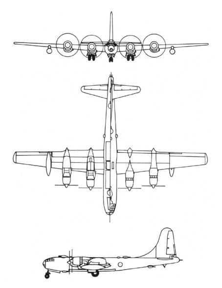
The Chinook’s fuselage is built around a cargo bay, in front of which is the flight deck and above it, at either end, the pylons holding the transmission for the two rotors. The two turbine engines are installed on either side of the aft pylon. The fuselage has sealed and compartmented fairing pods on each side of the lower fuselage, extending for almost three-quarters of the fuselage length to supplement the buoyancy of the sealed lower fuselage for water operations.

Self-sealing pressure refuelled crashworthy fuel tanks are in the external fairings on sides of fuselage with a total fixed fuel capacity of 3,899 litres. Provision for up to three additional long-range tanks in cargo area, each of 3,028 litres give a maximum fuel capacity (fixed and auxiliary) of 6,927 litres.

The constant cross-section cabin with side door at front and rear-loading ramp that can be opened in flight. Access to flight deck is from the cabin. Behind the cargo bay is a hydraulically-actuated ramp which greatly facilitates loading and unloading operations. On either side of the fuselage are two large fairings, housing the fuel tanks, landing gear shock absorbers and battery for the electrical system. The cargo bay has a volume of circa 42cu.m and can carry either 44 troops, 24 stretcher cases plus two medical attendants, or a weight of between eight and 11 tonnes. A hoist at the front of the bay can be used for lifting loads vertically through a hatch in the middle of the floor or for lowering items to the ground. The Chinook also has a cargo hook at the center of gravity for carrying slung loads (covered by removable floor panel so that load can be observed in flight), enabling it to operate as a flying crane.

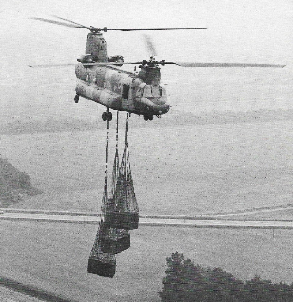
Three cargo hooks are fitted. The centre is capable of lifting 12 tons and the other two 9 tons each.

Two three-blade intermeshing contrarotating tandem rotors, the front rotor turning anti-clockwise, has rotor transmissions driven by connecting shafts from a combiner gearbox. Classic rotor heads with flapping and drag hinges are fitted with 225 rotor rpm. The manually foldable blades, usse Boeing Helicopters VR7 and VR8 aerofoils with cambered leading-edges, and the blades can survive hits from 23mm HEI and API rounds. A rotor brake is optional. To minimize the vibrations transmitted to the fuselage by the rotors, the helicopter has five vibration absorbers, one in the nose, two under the cockpit floor and two inside the aft pylon.
Differential fore and aft cyclic is for pitch attitude control, and differential lateral cyclic pitch (from rudder pedals) for directional control. Automatic control to keep fuselage aligned with line of flight. Dual hydraulic rotor pitch-change actuators: secondary hydraulic actuators in control linkage behind flight deck for autopilot/autostabiliser input; autopilot provides stabilisation, attitude hold and outer-loop holds.
A 67shp Solar turbine at the base of the aft pylon drives the electric generators and hydraulic pumps. The hydraulic system comprises a utility system, a No.1 flight control system and a No.2 flight control system. Electrical system includes two 40kVA air-cooled alternators driven by transmission drive system. Solar T62-T-2B APU drives a 20kVA generator and hydraulic motor pump, providing electrical and hydraulic power for main engine start and system operation on the ground.
Two pilots on the flight deck, with dual controls have a jettisonable door on each side of flight deck. Depending on seating arrangement, 33 to 55 troops can be accommodated in main cabin, or 24 litters plus two attendants, or vehicles and freight. Rear-loading ramp can be left completely or partially open, or can be removed to permit transport of extra-long cargo and in-flight parachute or free-drop delivery of cargo and equipment.
Main cabin door, at front on starboard side, comprises upper hinged section which can be opened in flight, and lower section with integral steps. Lower section is jettisonable. Triple external cargo hook system, with centre hook rated to carry maximum load of 11,793kg and the forward and rear hooks 7,711kg each, or 10,433kg in unison. Provisions are installed for a power-down ramp and water dam to permit ramp operation on water, for forward and rear cargo hooks, internal ferry fuel tanks, external rescue hoist, and windscreen washers.

The first YHC-1B made its initial flight on 21 September 1961, by which time the first production contract for CH-47A aircraft had been placed. These were powered initially by 1641kW Lycoming T55-L-5 turboshafts (subsequently by 1976kW T55-L-7 turboshafts), and deliveries of CH-47As began in December 1972.
The CH-47B replaced the original model, and was chosen by the US Army as the standard troop transport for the First Cavalry Division (Airmobile). The CH-47B is recognisable by the two thin fins at the base of the rear ramp, and has more powerful 2125kW T55-L-7C turboshafts, redesigned rotor blades and other detail refinements, the first of two prototypes making its first flight during October 1966, with deliveries beginning on 10 May 1967.
The CH-47B was followed by the CH-47C (Model 234) which had new 3802shp / 2,796kW T55-L-11A engines, strengthened transmission and new, larger 3,944 litres capacity fuel tanks. The first CH-47C flew on 14 October 1967 and deliveries began in spring 1968.
Nine aircraft similar to the CH-47C have been built for the Canadian Armed Forces, under the designation CH-147; deliveries began in September 1974. The CH-147 has the latest safety features and an advanced flight-control system, with a maximum land take-off weight of 22680kg and emergency water take-off weight of 20865kg.

Licence production of the CH-47C has also been undertaken by Ellicotteri Meridionali in Italy since 1970. Agusta, SIAI-Marchetti, and other Italian manufacturers are also involved in this programme.
After a number of setbacks, an order was confirmed for 26 CH-47Cs for the Italian Army and the first wholly Italian aircraft were delivered in 1974. The Italian order was followed first by an order for the Iranian Army (initially 20 aircraft) and then for Libya, Morocco, Egypt, Tanzania and Greece.

Under a US Army development programme, one each of the models CH-47A, CH-47B, and CH-47C were stripped down to the basic airframe, and rebuilt to an improved standard to serve as CH-47D prototypes. These upgraded CH-47Ds have more-powerful turboshaft engines and higher-rated transmissions; a redesigned avionics; and many design refinements. They also introduce an auxiliary power unit and a triple hook cargo-suspension system. Following a successful conclusion to flight testing of these prototypes by the US Army, Boeing Vertol started a programme of remanufacturing CH-47As to CH-47D standard, and the first of these was delivered in 1982.

The modernised CH-47D Chinook has been operational with the US Army since February 1984, and offers a payload more than twice that of the original CH-47A. Plans called for the eventual update of 436 CH-47A/B/Cs to D standard. Conversion rate was four per month, and the programme was scheduled to continue until 1993. Changes incorporated include uprated T55-L-712 engines and rotor transmission system, the latter with integral lubrication and cooling. Composite rotor blades are fitted, and avionics and other systems are upgraded. A CH-47D equipped with a retractable 11.6m (38ft) probe successfully completed in-flight refuelling trials with a USAF HC-130 tanker in 1985. Improvements developed for the CH-47D have been built into the current military export version, the CH-47D International Chinook (formerly the Model 414). Spain received six of these between July 1986 and April The 1987, with Bendix RDR-1400 weather radar mounted in the nose.

Under the designation Chinook HC. Mk 1, the Royal Air Force ordered 33 examples similar to the Canadian CH-147. They have British avionics and equipment, and a number of special provisions. The first was handed over in August 1980, and delivery of all 33 was completed during early 1982.

Ultimately, the CH-47 Chinook appeared in a D model with an export variant designated as the CH-47 “International Chinook”.

Boeing 308 Chinook of III Escuadron of Grupo Aereo 7, Argentina

Production by Boeing Vertol of new military Chinooks became limited to orders for the Model 414, which is an international export version and the MH-47E, a Special Forces variant of the CH-47D with night/low flying avionics and an inflight-refuelling probe.

Kawasaki license-produced the CH-47 “D” model as the CH-47J and CH-47JA models. The CH-47J is essen¬tially a CH-47D International Chinook, and a total of 54 were required by the JASDF/JGSDF.
Australia signed an order for 12 CH-47C Chinooks in March 1972 and these aircraft went into service with 12 Squadron, RAAF, based at Amberley.

From January 1991, 100 CH-47Ds fitted with engine air particle separator (also available for RAF variant). Standard in MH-47E and optional in International Chinook are two AlliedSignal T55-L-714 turboshafts, each with a standard power rating of 3,108kW continuous and emergency rating of 3,629kW. CH-47SD has T55-L-714A turboshafts with maximum continuous rating of 3,039kW. FADEC installed on late production CH-47Ds and CH-47SD. Normal fuel capacity in CH-47DS and MH-47E is 7,828 litres, but MH-47E can also operate with three long-range tanks in cargo area, each containing 3,028 litres, bringing total fuel capacity to 16,913 litres. CH-47D SOA and MH-47E have 8.97m refuelling probe on starboard side of forward fuselage.
US Army modernized some 300 of their 431 D-models to CH-47F standard with more powerful engines, as well as vibration reduction, improved avionics and digital mission systems and map display. The CH-47F first flew early in July 2001.

In late 1965, the first Armed/Armoured Chinook (ACH-47) was officially rolled out and testing was begun. The Armed/Armoured Chinook mounts an array of armament, as well as armor to protect the crew and vital parts of the aircraft against heavy calibre ground fire.
Mounted on the nose was an M-5 40mm Automatic Grenade Launcher. This turret-mounted weapon was controlled by the copilot, who was able to cover an extensive area on either side of the flight path. Complementing this nose turret, pylons on each side of the aircraft carried fixed forward-firing weapons including a 22mm gun and either a 19-round 2.75 inch rocket pod, or a 7.62mm high-rate-of-fire Gatling machine-gun.
The sides of the aircraft were protected by four gunners stationed two to either side of the cabin. Each of these gunners was provided with either a 7.62mm or 12.7mm calibre machine-gun on flexible mounts. Another gunner was stationed aft with the same type weapons mounted on the rear loading ramp. From this vantage point, the gunner could protect the aircraft from ground fire after the aircraft had passed. This aircraft carried a ton of expendable munitions. The Armed/Armoured Chinook was provided with a new type of steel armour plate which was built into the crew seats and protected their torsos. Similar in configuration to the CH-47A, three of these were evaluated in Vietnam, but no further examples were built.

Despite their design capability, on one memorable occasion in Vietnam a Chinook evacuated 147 refugees and their possessions in a single flight.

CH-47 Chinook

After the CH-47D, Boeing Vertol completed a project in summer 1978 for a commercial version of the same aircraft, primarily intended for operators of oil platforms but also suitable for the prospecting of remote areas.
The airframe of the Model 234 is based on that of the military Chinooks, but has many new features such as fiberglass blades of larger chord in place of metal ones, different-sized fairings along the sides of the fuselage containing fuel, a longer nose to house the weather radar and front landing gearwheels shifted farther forward.

Two versions of the Model 234 were available: Model 234LR – a long-range version with lateral fairings almost twice the size of the original Chinook ones, which have 6360kg fuel capacity, and Model 234UT – a utility version in which the fuel tanks of 1826kg are contained in four smaller fairings level with each wheel. The helicopter can be converted from one version to the other. The three rotor blades are interchangeable and maintenance has been reduced to a minimum, with considerable savings in running costs. The service life of the engines has also been increased to 1800 hours TBO.
The rotors of the civil Chinook are powered by two Textron Lycoming AL 5512 turboshafts, pod-mounted on sides of rear rotor pylon, via a combining gearbox and interconnecting shafts which enable both rotors to be driven in emergency by either engine. Each engine has maximum T-O rating of 3,039kW, maximum continuous rating of 2,218.5kW, and 30 minutes contingency rating of 3,247kW.

The passenger compartment of the long-range version has 44 seats arranged in four rows with a central corridor and there is a baggage compartment at the rear of the fuselage; it has a crew of three. The 234LR is fitted with cabin windows similar to those of the Boeing 727 airliner, airliner seats at 84cm pitch, overhead baggage lockers, and a number of other ‘airliner’ features. In all-passenger versions of the 234, a galley and toilet are fitted. A typical mixed combination in the utility version consists of 11 passengers and 7250kg of freight. This version also has a cargo hook at the center of the fuselage capable of lifting up to 12700kg, and external cargoes slung from as many as four separate hooks.
Long-range model has two fuel tanks, one in each fuselage side fairing, with total capacity of 7,949 litres. Utility model has two drum-shape internal tanks, with total capacity of 3,702 litres. Extended-range model has both fuselage side and internal drum tanks. Single-point pressure refuelling.
The 234LR has more power and greater take-off weight (23133kg with an external load compared with 20865kg of the military model). The helicopter can carry an internal load of 9526kg in the cabin, which is 9.19m long, 2.51m wide, and 1.98m high.
The first Commercial Chinook made its maiden flight on 19 August 1980, and FAA and CAA certification came on 19 and 26 June 1981 respectively. The FAA and CAA certificated the 234 LR Combi in the Summer of 1982. In the 10 months since the first flight, two BV 234s completed 425 hrs of testing in 361 flights. It had been certificated at a weight of 48,500 lb / 22,000 kg and a range of 565 nm / 1047 km.
The first order for the Boeing Vertol 234 came from British Airways Helicopters in 1978 for three (later increased to six), to meet a requirement for offshore work in the North Sea accepting the first in December 1980. Since then Helicopter Service in Norway and ARCO in Alaska have also put the type in service for offshore support.

The BV.234UT conversion for fire fighting and can carry a 3000 USG bucket as an underslung load. There are two 500 USG fuel tanks installed inside the fuselage, but 20 seats are retained.

Total 735 CH-47A/B/C built and 479 CH-47D/MH-47E conversions authorised for US Army. Another 166 built by Boeing for export customers together with 45 kits. Agusta (Meridionali) production totals 136, with Kawasaki having built 54 by January 1999. Total Chinook orders, including civil, amount to 1,155.
As well as for the US Army, the Chinook has been built for the Royal Australian Air Force (12) and the Spanish Ejercito del Aire (12), and others have been sold to Argentina, and Thailand.

Boeing-Vertol 234

Gallery

Versions:

CH-47A: Initial production version, powered by two 1,640kW Lycoming T55-L-5 or 1,976kW T55-L-7 turboshaft engines. Total 354 built for US Army.

CH-47B: Developed version with 2,125kW T55-L-7C turboshaft engines, redesigned rotor blades with cambered leading-edge, blunted rear rotor pylon, and strakes along ramp and fuselage for improved flying qualities. First of two prototypes flew for the first time early October 1966. Deliveries began 10 May 1967. Total 108 built for US Army.

CH-47C: Developed version with uprated transmissions and 2,796kW T55-L-11A; integral fuel capacity increased to 3,944 litres; first flight 14 October 1967; 270 delivered to US Army from Spring 1968; 182 US Army CH-47Cs retrofitted with composite rotor blades; integral spar inspection system (ISIS) introduced 1973 together with crashworthy fuel system retrofit kit. Transmissions of some As and Bs upgraded to CH-47C standard.
Agusta (Meridionali) built 136 by 31 December 1995.

CH-47D: US Army contract to modify one each of CH-47A, B and C to prototype Ds placed 1976; first flight 11 May 1979; first production contract October 1980; first flight 26 February 1982; first delivery 31 March 1982; initial operational capability (IOC) achieved 28 February 1984. First multiyear production contract awarded 8 April 1985 for 240 aircraft; second multiyear production contract for 144 CH-47Ds awarded 13 January 1989, bringing total CH-47D (and MH-47E) ordered to 472; further two Gulf War attrition replacements authorised August 1992 (these new-build); seven ex-Australian rebuilds funded June 1993 for delivery January to November 1995.
CH-47D update included strip down to bare airframe, repair and refurbish, fit AlliedSignal T55-L-712 turboshafts, uprated transmissions with integral lubrication and cooling, composite rotor blades, new flight deck compatible with night vision goggles (NVG), new redundant electrical system, modular hydraulic system, advanced automatic flight control system, improved avionics and survivability equipment, Solar T62-T-2B APU operating hydraulic and electrical systems through accessory gear drive, single-point pressure refuelling, and triple external cargo hooks. Principal external change is large, rectangular air intake in leading-edge of rear sail. Composites account for 10 to 15 per cent of structure. About 300 suppliers involved.
Test programme began late 1995 of Chinook with vibration-reducing dynamically tuned fuselage.

MH-47D Special Operations Aircraft: Two battalions equipped with 11 CH-47D SOA fitted with refuelling probes (first refuelling July 1988), thermal imagers, AlliedSignal RDR-1300 weather radar, improved communications and navigation equipment, and two pintle-mounted 7.62mm machine guns. Navigator/commander’s station also fitted.

GCH-47D: At least 12 Chinooks grounded for engineer training.

JCH-47D: Two CH-47Ds modified for special testing.

MH-47E: Special Forces variant; planned procurement 51, deducted from total 472 CH-47D conversions but only 25 received, including 14 not covered by multiyear production contract; prototype development contract 2 December 1987. Prototype (88-0267) flew 1 June 1990; delivered 10 May 1991; initial production aircraft flown 1992. Following mission software problems, deliveries began January 1994; last of 26 (including prototype) received April 1995.

MH-47E has nose of Commercial Chinook to allow for weather radar, if needed; forward landing gear moved 1.02 m (3 ft 4 in) forward to allow for all-composite external fuel pods (also from Commercial Chinook) that double fuel capacity; Brooks & Perkins internal cargo handling system. Chinook HC. Mk 2/2A: RAF version; Mk 1 designation CH47-352; all survivors of original 41 HC. Mk 1s upgraded to HC. Mk 1B; UK MoD authorised Boeing to update 33 (later reduced to 32) Mk 1Bs to Mk 2, equivalent to CH-47D, October 1989; changes include new automatic flight control system, updated modular hydraulics, T55-L-712F power plants with FADEC, stronger transmission, improved Solar 71 kW (95 shp) T62-T-2B APU, airframe reinforcements, low IR paint scheme, long-range fuel system and standardisation of defensive aids package (IR jammers, chaff/flare dispensers, missile approach warning and machine gun mountings). Smiths Industries HUMS being installed. Requirement exists for FLIR. Conversion continued from 1991 to July 1995. Chinook HC. Mk 1B ZA718 began flight testing Chandler Evans/Hawker Siddeley dual-channel FADEC system for Mk 2 in October 1989. Same helicopter to Boeing, March 1991; rolled out as first Mk 2 19 January 1993; arrived RAF Odiham 20 May 1993; C(A) clearance November 1993. Final Mk 1 withdrawn from service, May 1994, at which time 11 Mk 2s received. Further three new-build Mk 2s ordered 1993, for delivery from mid-1995; decision to order further 14 Mks 2A/3 announced March 1995. Mk 2A has dynamically tuned fuselage. Total RAF procurement 58 CH-47C/D/Es. First HC. Mk 2A handed over in USA 6 December 1997; arrived UK for clearance trials 18 December; remainder delivered by end of 1998.

Chinook HC. Mk 3: Eight of 14 additional RAF Chinooks announced March 1995 assigned to Special Forces; configuration similar to MH-47E, including large fuel panniers, weather radar and refuelling probes. First flight mid October 1998; deliveries from March 2000.

HT.17 Chinook: Spanish Army version.

Boeing 414: Export military version; superseded by CH-47D International Chinook.

CH-47D International Chinook: Boeing 414-100 first sold to Japan; Japan Defence Agency ordered two for JGSDF and one for JASDF Spring 1984; first flight (N7425H) January 1986 and, with second machine, delivered to Kawasaki April 1986 for fitting out; co-production arrangement (see under Kawasaki). International Chinook available in four versions with combinations of standard or long-range (MH-47E type) fuel tanks and T55-L-712 SSB or T55-L-714.

CH-47SD ‘Super D’: Latest variant on offer for export; embodies some improvements first installed on the MH-47E for US special operations forces. AlliedSignal T55-L-714A turboshaft with FADEC chosen as standard power plant; single-point pressure refuelling and jettison capability on both sides of aircraft, with fuel contained in two ballistic and crash-resistant tanks; total usable capacity is 7,828 litres (2,068 US gallons; 1,722 Imp gallons); CH-47SD also has Smiths digital fuel quantity gauging system in place of Ragen analogue system. Simplified structure offers benefits in maintainability and reliability.
CH-47SD also incorporates modernised NVG-compatible cockpit with avionics control management system (ACMS), utilising proven military and commercial off-the-shelf equipment on single console to reduce pilot workload and with provisions for growth. Avionics suite is comparable to that of baseline CH-47D, but features two embedded INS/GPS units as well as AN/ARN-147 VOR/ILS and AN/ARN-149 ADF, plus space and power provisions for Tacan. Rollout scheduled for 31 October 1999.

CH-47F Improved Cargo Helicopter (ICH): Boeing programme for improved Chinook configuration for US Army involving the development and production of a new version that will remain operational and cost-effective until a new cargo helicopter is developed between 2015 and 2020 under the current Army Aviation Modernisation Plan.

234 LR Long Range: About twice CH-47 fuel load in composites tanks attached to fuselage flanks with anti-vibration mounts; flight deck floor on shockmounts; 44-passenger interior (on shockmounts), with toilet and galley, based on Boeing airliners; walk-on baggage bins on rear ramp; alternative mixed passenger/cargo or all-cargo layouts.

234 ER Extended Range: Typical configurations are 17 passengers and two tanks for additional 1,621km or 32 passengers and single cabin fuel tank; FAA certificated May 1983.

234 UT Utility: External fuel cells replaced by two cylindrical tanks in forward fuselage: FAA supplemental-type certificate October 1981 at maximum gross weight 23,133kg with external loads up to 12,700kg on single hook; approved for 24 passengers and operation at up to 3,660m at full gross weight. No known orders, but several converted to this configuration.

234 MLR Multipurpose Long Range: Similar to 234 LR but with utility interior; can be reconfigured in 8 hours; four men can handle cabin cylindrical fuel tanks and ramp baggage bins.

234-100: Commercial equivalent of CH-47D Chinook, proposed to be built in China under co-production agreement between Boeing and Harbin Aircraft Manufacturing Company (HAMC). Minimum launch commitment set at 10 units, with at least 50 required over a five-year period to make it economically viable.

234 Combi: Firefighting modification by Columbia Helicopters equipped to carry 19 firefighters and equipment, capable of dropping 11,370 litres of water. Also carries 9,854 litre Bambi bucket.

Specifications:

Boeing Vertol Model 114

YHC-1B / YCH-47A Chinook
Engines: 2 x 1641kW Lycoming T55-L-5 turboshafts – subsequently 1976kW T55-L-7 turboshafts
Fixed fuel capacity: 3,899 lt
Long-range fuel: 2 x 3,028 lt
Maximum fuel capacity (fixed and auxiliary): 6,927 lt.
External cargo hook capacity centre: 11,793kg
External cargo hook capacity forward/rear: 7,711kg each
Max external load: 10,433kg

CH-47A:
Engines: 2 x 1,640kW Lycoming T55-L-5 or 1,976kW T55-L-7 turboshaft engines.

CH-47B
Engines: 2 x T55-L-7C turboshafts, 2125kW / 2850 shp
Rotor dia: 60 ft 0 in (18.29 m)
Length: 99 ft 0 in (30.18 m)
Height: 18 ft 7 in (5.67 m)
Max TO wt: 40,000 lb (18,144 kg)
Max level speed: 144 mph (232 kph)

Model 234 / CH-47C
Engines: 2 x 3802shp / 2,796kW T55-L-11A
Fuel capacity: 3,944 litres
Length: 51 ft.
Length with rotors turning: 30.18m
Height: 5.68m
Rotor dia: 18.29m, 60 ft.
Max speed: 286km/h
Cruise Speed: 257km/h, 120 knots
Ceiling: 15,000 ft.
Service ceiling: 3290m
Radius of Action internal fuel: 240km
Max ROA: 750km
Range: 1,420 miles.
Seating: 33 fully equipped soldiers
Empty weight: 9736kg
Max take-off weight: 17463kg
Internal load cap: 22,000 lb
External load cap: 25,000 lb
Crew: 2 pilots, 1 Loadmaster, 1 aircrew

CH-147
Maximum land take-off weight: 22680kg
Emergency water take-off weight: 20865kg.

CH-47D
Engines: 2 x AlliedSignal T55-L-712 turboshafts, 4431shp
APU: Solar T62-T-2B
Rotor dia: 18.3 m.
Fuselage length: 15.5 m.
No. Blades: 2 x 3.
Length: 51.02ft (15.55m)
Height: 18.93ft (5.77m)
Maximum Speed: 180mph (290kmh; 157kts)
Maximum Range: 264miles (425km)
Rate-of-Climb: 1,522ft/min (464m/min)
Service Ceiling: 8,448ft (2,575m)
HIGE: 8200 ft.
HOGE: 4950 ft
Accommodation: 3 + 35 (up to 55)
Empty Weight:23,402lbs (10,615kg)
Maximum Take-Off Weight: 50,001lbs (22,680kg)
Payload: 12,065 kg.
Fuel cap: 3900 lt.
Crew: 3.
Pax: 33.

Model 414 / CH-47D International Chinook
Engine: 2 x Textron Lycoming T55-712 SSB, 4431shp.
Instant pwr: 2237 kW.
MTOW: 24,494 kg.
Payload: 10,670 kg.
Max speed: 156 kts.
HOGE: 10,100 ft.
Crew: 2.
Pax: 44

CH-47F Chinook
Engine: 2 x Honeywell T55-GA-14A-714

Chinook HC. Mk 1

Chinook HC. Mk 1B

Chinook HC. Mk 2
Engines: 2 x T55-L-712F
APU: Solar 71 kW (95 shp) T62-T-2B

Chinook Mk 2A

Chinook HC. Mk 2/2A

Chinook Mks 2A/3

Chinook HC. Mk 3

HT.17 Chinook

CH-47 “International Chinook”
Engines: 2 x T55-L-712 SSB or T55-L-714

GCH-47D

JCH-47D

MH-47D Special Operations Aircraft

MH-47E
Engines: 2 x AlliedSignal T55-L-714 turboshafts, standard power rating of 3,108kW continuous and emergency rating 3,629kW
MTOW: 24,494 kg.
Payload: 12,284 kg.
Normal fuel capacity: 7,828 litres
Long-range fuel capacity: 16,913 litres
Max speed: 154 kts.
Max range: 1136 km.
HIGE: 9800 ft.
HOGE: 5500 ft.
Crew: 2.
Pax: 44

CH-47J

CH-47JA

CH-47SD ‘Super D’
Engines: 2 x T55-L-714A turboshafts, maximum continuous rating 3,039kW
Normal fuel capacity: 7,828 lt (2,068 US gallons; 1,722 Imp gallons)

Armed/Armoured Chinook / ACH-47
Armament: 1 x M-5 40mm Automatic Grenade Launcher
1 x 22mm gun
1 x 19-round 2.75 inch rocket pod, or 1 x 7.62mm Gatling machine-gun.
5 x 7.62mm or 12.7mm calibre machine-gun

Model 234LR
Engines: 2 x Textron Lycoming AL 5512 turboshafts T-O rating of 3,039kW, maximum continuous rating of 2,218.5kW, and 30 minutes contingency rating of 3,247kW.
TBO: 4000 hrs.
Main rotor: 60 ft.
Length: 99 ft.
Height: 18.7 ft.
Max ramp weight: 48,500 lbs.
Max takeoff weight: 48,500 lbs.
Standard empty weight: 25,200 lbs.
Max useful load: 23,300 lbs.
Zero fuel weight: 26,403 lbs.
Max landing weight: 48,500 lbs.
Max sling load: 28,000 lbs.
Max internal load: 9526kg
Disc loading: 8.6 lbs/sq.ft.
Power loading: 7.2 lbs/hp.
Max rate of climb: 1180 fpm.
Service ceiling: 8500 ft.
Hover in ground effect: 8500 ft.
Hover out of ground effect: 2700 ft.
Max speed: 145 kts.
Normal cruise @ 5000 ft: 135 kts.
Fuel flow @ normal cruise: 2650 pph.
Endurance @ normal cruise: 5.1 hr.
Cabin: 9.19m x 2.51m x 1.98m
Max usable fuel: 14,091 lbs / 7,949 lt / 6360kg
Passenger capacity; 44

234UT
Engines: 2 x Textron Lycoming AL 5512 turboshafts T-O rating of 3,039kW, maximum continuous rating of 2,218.5kW, and 30 minutes contingency rating of 3,247kW.
Engine TBO: 1800 hr
Rotor diameter: 18.29m
Length with rotors turning: 30.18m
Height: 5.68m
Maximum gross weight: 23,133kg
Empty weight: 9576kg
Max speed: 269km/h
Hovering ceiling: 3155m
Service ceiling: 4570m
Range: 1010km
Fuel capacity: 1826kg / 3,702 lt
Cabin: 9.19m x 2.51m x 1.98m
Max external load: 12,700kg
Passenger: 24
Ceiling: 3,660m

234 MLR Multipurpose Long Range

234-100

234 Combi

Boeing-Vertol 107 / CH-46 / Vertol YHC-1

In 1956, Vertol began preliminary design and engineering of a twin-turbine transport helicopter for commercial and military applications. The main objective was to take full advantage of the high power, small size and light weight of the shaft-turbine engines then becoming available. To achieve the best possible hovering performance, the traditional Vertol tandem-rotor layout was retained, and the turbines were mounted above the rear of the cabin, on each side of the aft rotor pylon. This results in maximum unobstructed cabin area and permits the use of a large rear ramp for straight-in loading of vehicles and bulky freight.

Boeing-Vertol 107 / CH-46 Article

Construction of a prototype, designated Model 107, was started in May 1957, and this aircraft flew for the first time on 22 April 1958, powered by two 641kW Lycoming T53 turboshaft engines. It was designed for water landing capability, without the addition of special flotation gear or boat hull design, and was intended to carry 23 to 25 passengers in normal airline standard accommodation.

Vertol 107 No.1

The new Model 107 prototype N74060 with two 877shp Lycoming T53 turbines flew on 12 August 1958.

In July 1958, the US Army ordered 10 Model 107s, designated YHC-1A; seven with the uprated 1065shp General Electric YT58 turbine and three with the Lycoming T53, and a rotor diameter increased by 0.6m.

YHC-1A

The first YHC-1A flew on 27 August 1959, but in the meantime, the US Army had ordered five YHC-1Bs (Model 114 later known as the CH-47 Chinook), a scaled-up variant which was better suited to meet its need for a tactical transport helicopter, and consequently the order for the Model 107 was reduced to only three machines (serials 58-5514 through -5516). These machines were used primarily to familiarize Army flight crews with the capabilities of turbine-powered helicopters, and all three were eventually returned to the manufacturer.

The third of these was later returned to the company which equipped it with 783kW General Electric T58-GE-6 turboshaft engines and rotors of increased diameter, and this derivative was fitted out with a commercial interior as the Model 107-II prototype. This first flew on 25 October 1960. By that time Vertol had become a division of The Boeing Company. The first production model of the airliner spec 107 II followed on 19 May 1961 and FAA certification was received on 26 January 1962, entering scheduled service with New York Airways 1 July that year. Eight helicopters were delivered and began scheduled services between mid town Manhatten and Kennedy and La Guardia aoirports. Following this initial order remaining commercial variants were built by Kawasaki.

When the US Navy set up a new design competition for a medium-lift transport helicopter in 1960, this was won by the Boeing-Vertol 107M, a modified version of the YHC-1A powered by T58-GE-8 engines in February 1961. A batch of 50 was initially ordered, the first of which was tested in October 1962. Ordered into production under the designation HRB-1 (changed to CH-46A Sea Knight in 1962), the 107M was used for troop transport. The first order for the CH-46A assault transport version for the US Marine Corps was placed in February 1991, with first flight on 16 October 1962. This basic model accommodates a typical total of 26 troops or 15 casualty litters.

In 1963 Sweden bought four more Boeing Vertol 107, bringing to 13 the total ordered for its Air Force and Navy, designated HKP-4.

Testing continued into late 1964, with the first US Marine squadrons taking these aircraft into service in early 1965.
Four squadrons were operating CH-46As by June 1965 and the type entered service in Vietnam in March 1966, replacing the Sikorsky H-34.During the V ietnam War the Marines also installed a 7.62mm machine gun, which was fired through the cabin door. A total of 498 have been ordered by the Marine Corps and 24 by the US Navy.
Several variants have been produced including the CH-46A for the Marines (160); the UH-46A Sea Knight for the US Navy (24) with first deliveries to Utility Helicopter Squadron 1 in July 1964) the CH-46D for the USMC, generally similar to the CH-46A, but with 1044kW T58-GE-10 turboshaft engines (266); the UH-46D for the US Navy (10); the UH-46B for evaluation by the USAF; the RH-46E minehunters for the US Navy, and the CH-46F for the Marines , generally similar to the CH-46D, but with additional avionics (174).
The US Navy UH 46 model accommodated a typical total of 26 troops or 15 casualty litters but also able to carry 3175 kg (7,000 lb) of cargo, including vehicles loaded through the full section rear ramp door, for use in the vertrep (vertical replenishment) of ships at sea. Both Sea Knight families can have rescue hoists and are equipped for limited amphibious operation, though they are not intended for sustained alighting on rough seas.
Some 669 Sea Knights were built; US Navy and Marine Corps models serving in Operation Desert Storm.
A total of 624 models were delivered by 1971, and most surviving examples have been subjected to major update programmes which include fitting glassfibre rotor blades. The best 273 Sea Knights in US Marine Corps service were progressively being rebuilt as CH 46E helicopters with the more powerful 1394kW General Electric T58-GE-16 turboshaft engines, replacing the 1,250 or 1,400 shp (932 or 1044 kW) T58 engines origi¬nally fitted, as well as numerous improvements to improve reliability, res¬cue capability and ability to survive a crash on land or on water. Since 1981, 368 kits were supplied to provide further modifications to im¬prove safety and reduce costs.
The CH/UH-46 carries a crew of three, 25 troops and troop commander. Door at front of troop compartment on starboard side. Door is split type; upper half rolls on tracks to stowed position in fuselage crown, lower half is hinged at the bottom and opens outward, with built-in steps. Loading ramp and hatch at rear of fuselage can be opened in flight or on the water. Floor has centre panel stressed for 1,464kg/sq.m. A row of rollers on each side for handling standard military pallets or wire baskets. Outer portion of floor is vehicle treadway stressed for 454kg rubber-tyred wheel loads. Cargo and personnel hoist system includes a variable-speed winch capable of 907kg cable pull at 9m/min for cargo loading or 272kg cable pull at 30m/min for personnel hoisting; it can be operated by one man. A 4,535kg capacity hook for external loads is installed in a cargo hatch in the floor.
The cabin is heated by a Janitrol combustion heater and hydraulic system provides 105kg/sq.cm pressure for flying control boost, 210kg/sq.cm for other services. Electrical system includes two 40kVA AC generators and a Leland 200A DC generator. Solar APU provides power for starting and systems check-out.
CH-46 has dual stability augmentation systems and automatic trim system.
Featuring two three-blade rotors in tandem, rotating in opposite directions. The CH/UH-46 has power-operated blade folding. Power is transmitted from each engine through individually overrunning clutches into the aft transmission, which combines the engine outputs, thereby providing a single power output to the interconnecting shaft which enables both rotors to be driven by either engine.
The structure is square-section stressed-skin semi-monocoque structure built primarily of high-strength bare and alclad aluminium alloy. Transverse bulkheads and built-up frames support transmission, power plant and landing gear. Loading ramp forms undersurface of upswept rear fuselage on utility and military models. Baggage container replaces ramp on airliner version. Fuselage is sealed to permit operation from water.
Non-retractable tricycle landing gear has twin-wheels on all three units. Oleo-pneumatic shock-absorbers manufactured by Loud (main gear) and Jarry (nose gear). Goodyear tubeless tyres size 8 x 5.5, pressure 10.55kg/sq.cm, on all wheels. Goodyear disc brakes.

Six utility models, almost identical to the CH-46A, were delivered to the RCAF in 1963-4 under the designation CH-113 Labrador, and 12 similar aircraft were built for the Canadian Army during 1964-5, these being designated CH-113A Voyageur. The CH 113 Labrador had a range of over 650 miles (1,050 km). Under a Canadian Armed Forces’ Search And Rescue Capability Upgrade Project (SARCUP), Boeing of Canada was contracted to modify six CH-113s and five CH-113As to an improved SAR standard by mid-1984, with extra fuel, weather radar, a water dam for use of the rear ramp at sea and an APU (auxiliary power unit).

CH-113 Labrador of 103rd Rescue Sqn, Gander

In 1962-3 Boeing Vertol supplied 14 Model 107-IIs to Sweden for service with the air force in the search and rescue role, and with the navy for ASW and minesweeping duties: both of these versions have the designation HKP-4. Sweden uses the Gnome engined HKP 7 version for ASW and mines¬weeping duties.

Kawasaki Heavy Industries obtained a licence in December 1965 to build the Model 107 in Japan in civil and military versions resulting in 12 new versions: the KV-107/11-2 commercial version for passenger transport adopted by Kawasaki, the Thai government and New York Airways; the KV-107/11-3 minehunters; the KV-107/11-4 for tactical transport, 59 of which have been built for the Japanese Ground Self-Defense Force; the KV-107/11-5 rescue version for the Japanese Air Self-Defense Force and the Swedish Navy (38 built); the KV-107/11-7 six-eleven-seat VIP transport version, only one of which has been built for the Thai government; and the KV-107/IIA version for hot climates and high altitudes.
Kawasaki obtained in 1965 exclusive rights to manufacture this tandem rotor helicopter and sell it worldwide. The first KV107II obtained Japanese and US type approval in Spring 1968. The 107 Model II standard accommodation is for two pilots, stewardess and 25 passengers in airliner. Seats in eight rows, in pairs on port side and single seats on starboard side (two pairs at rear of cabin) with central aisle. Airliner fitted with parcel rack and a roll-out baggage container, with capacity of approximately 680kg, located in underside of rear fuselage. Ramp of utility model is power-operated on the ground or in flight and can be removed or left open to permit carriage of extra long cargo.
The naval KV 107II 3 is a specialized MCM (mine countermeasures) helicopter, of which nine serve with the JMSDF’s 111th Air Wing. This version has up¬rated engines (1,400 shp/1044 kW) in¬stead of 1, 50 shp/932 kW) and com¬prehensive equipment for mine¬sweeping and retrieval, as well as long range tanks, cargo hook and towing gear.

Variants:

107 Model II: Standard commercial version, with two 932kW (1,250 shp) General Electric CT58 turboshaft. Available as an airliner with roll-out rear baggage container or utility model with rear-loading ramp.

CH-46A (formerly HRB-1) Sea Knight: US Marine Corps assault transport version of the 107 Model II powered by two 932kW General Electric T58-GE-8B turboshafts.

CH-46D Sea Knight: Generally similar to CH-46A, but with 1,044kW General Electric T58-GE-10 turboshaft and cambered rotor blades.

CH-46E Sea Knight: Upgraded CH-46A with 1,394kW General Electric T58-GE-16 turboshafts and other modifications including provision of crash attenuating seats for pilot and co-pilot, a crash and combat resistant fuel system and improved rescue system. Initial fleet modifications began in 1977, and the first CH-46E modified at Cherry Point NV, Naval Rework Facility was rolled out 3 August 1977.

CH-46F Sea Knight: Generally similar to CH-46D, with the same engines and rotor blades. Contains additional electronics equipment. All CH-46s delivered since July 1968 were of this version.

UH-46A Sea Knight: Similar to CH-46A. Ordered by US Navy for operation from AFS or AOE combat supply ships to transport supplies, ammunition and missiles as well as aviation spares to combatant vessels under way at sea. Secondary tasks include transfer of personnel and SAR. First deliveries in July 1964.

UH-46D Sea Knight: Generally similar to UH-46A, but with 1,044kW General Electric T58-GE-10 shaft turbine engines and cambered rotor blades. UH-46s delivered since September 1966 were of this version.

CH-113 Labrador: Six utility models delivered to RCAF in 1963-64 for SAR duties. Generally similar to CH-46A. Two 932kW General Electric T58-GE-8B turboshafts. Larger capacity fuel tanks (total 3,408 litres) giving a range of over 1,050km. All six upgraded under Search and Rescue Capability Upgrading Programme (SARCUP).

CH-113A Voyageur: Twelve aircraft in a similar configuration to that of CH-46A, delivered to Canadian Army in 1964-65 as troop and cargo carriers in logistical and tactical missions. Eight upgraded to SARCUP configuration.

Hkp 4C: Built for Royal Swedish Navy (45) and Air Force (10) in 1962-63, with Bristol Siddeley Gnome H.1200 turboshaft engines and fuel tanks of 3,786 litres capacity. Naval version has equipment for anti-submarine and mine countermeasures operations. Since upgraded with Gnome H.1400 turboshafts and new avionics.

HH-46D: Rescue version in service with the US Navy.

UH-46D: Base utility and rescue helicopter. In service with the US Navy.

KV-107/II-2: airline version, with accommodation for two flight crew, a stewardess and 25 passengers; 11 built; improved KV-107/IIA-2 available

KV-107/11-3: mine counter-measures (MCM) version for JMSDF (two), plus seven of the uprated KV-107/11A-3 model

KV-107/II-4: tactical cargo/troop transport for JGSDF with strengthened cabin flooring; 42 supplied as such, with the last of 18 uprated KV-107/ IIA-4 versions delivered in late 1981

KV-107/II-5: designation of 13 long-range SAR helicopters for JASDF; 19 uprated, but otherwise similar aircraft, are designated KV-107/IIA-5, the last three being delivered during 1981; eight KV-107/II-5s supplied to Swedish navy without powerplant, these having Rolls-Royce Gnome H.1200 turboshafts installed in Sweden; Swedish navy designation HKP-4C

KV-107/II-7: designation of one six/eleven-seat VIP transport

KV-107/11A-17: designation of single long-range transport for Tokyo Metropolitan Police Department; has a forward passenger compartment and aft cargo hold

KV-107/II-SM-1: designation of four helicopters equipped as firefighters

KV-107/IIA-SM-2: aeromedical and rescue version

Gallery

Specifications:

YHC-1 Chinook
Engines: 2 x GE T58 gas turbines
Main rotor: 48’4″
Length: 52’8″
Speed: 155 mph

Model 107
Engines: 2 x Lycoming T53 turboshaft
Rotor diameter: 50 ft / 15.24 m
Fuselage length: 44 ft 7 in / 13.59 m
Overall length: 25.4o m / 83 ft 4 in
Height: 5.09 m / 16 ft 9 in
Cruise: 120 kt / 222 kph
Endurance: 2.2 hr
Passenger capacity: 25

Model 107
Engines: 2 x Lycoming T53 turboshaft, 641kW, 877shp
Rotor diameter : 60.007 ft / 18.29 m
Length : 99.016 ft / 30.18 m
Max take off weight : 50406.3 lb / 22860.0 kg
Max. speed : 161 kt / 298 km/h
Range : 100 nm / 185 km
Crew : 2+44

Model 107-II prototype
Engines: 2 x General Electric T58-GE-6 turboshaft, 783kW

107 Model II
Engines: 2 x General Electric CT58 turboshaft, 932kW (1,250 shp)

YHC-1A
Engines: 2 x General Electric YT58 turbine, 1065shp

107M / CH-46A / HRB-1 Sea Knight
Engines: 2 x General Electric T58-GE-8B turboshafts, 932kW
accommo¬dates 26 troops or 15 casualty litters.

CH-46D Sea Knight:
Engines: 2 x General Electric T58-GE-10 turboshaft, 1,044kW
External hook capacity: 4,535kg

CH-46E Sea Knight:
Engines: two 1,870 shp (1394 kW) General Electric T58 16 turboshafts.
Main rotor diameter: 15.24 m (50 ft 0 in)
Length overall: 25.70 m (84 ft 4 in)
Height: 5.09 m (16 ft 8.5 in)
Rotor disc. Area: 364.8 sq.m (3,927.0 sq ft)
Fuselage length: 44.82ft (13.66m)
Empty weights: 5240kg (11,5851b)
Maximum take off: 9706 kg (21,400 lb)
External hook capacity: 4,535kg
Maximum speed: 267 km/h (166 mph / 144kts)
Cruising speed: 193 km/h (120 mph)
Range (3000 kg/6,614 1b payload): 175 km (109 miles)
Maximum Range: 690miles (1,110km)
Rate-of-Climb: 1,715ft/min (523m/min)
Service Ceiling: 9,498ft (2,895m; 1.8miles)
Accommodation: 3 + 25

CH-46F Sea Knight
External hook capacity: 4,535kg

RH-46E

UH-46A Sea Knight
External hook capacity: 4,535kg

UH-46B
External hook capacity: 4,535kg

UH-46D Sea Knight:
Engines: 2 x General Electric T58-GE-10 turboshafts, 1,044kW
External hook capacity: 4,535kg

CH-113 Labrador
Engines: 2 x General Electric T58-GE-8B turboshafts, 932kW, 1250 shp
Rotor dia: 50 ft 0 in (15.24 m)
Length: 83 ft 4 in (25.4 m)
Height: 16 ft 8.5 in (5.09 m)
Max TO wt: 21,400 lb (9707 kg)
Max level speed: 157 mph (253 kph)
Fuel capacity: 3,408 lt
Range: 1,050+km

CH-113A Voyageur

Hkp 4C
Engines: 2 x Bristol Siddeley Gnome H.1200 turboshaft (upgraded with Gnome H.1400)
Fuel capacity: 3,786 lt

HH-46D

UH-46D

KV-107/II-2
Engines: 2 x 1,250 shp/932 kW
Crew: 2
Accommodation: 1 stewardess, 25 passengers

KV-107/IIA
Engines: 2 x Ishikawajima Harima CT58 IHI 140 1 turbo¬shaft, 1250 shp/932 kW

KV-107/IIA-2
Engine: 2 x General Electric CT58-140-1 turboshaft, 1044kW / 1,400 shp
Rotor diameter: 15.24m
Length with rotors turning: 25.4m
Height: 5.09m
Max take-off weight: 9707kg
Max speed: 254km/h
Cruising speed: 241km/h
Service ceiling: 5180m
Range with max fuel: 1097km
Accommodation: 1 stewardess, 25 passengers

KV-107/11-3
Engines: 2 x 1,400 shp/1044 kW

KV-107/IIA-3
Engine: 2 x 1,400 shp General Electric CT58 40 I, or 1,250 shp Ishikawajima Harima CT58 IHI 140 1 turbo¬shaft

KV-107/II-4
Engines: 2 x 1,250 shp/932 kW

KV-107/II-5
Engines: 2 x 1,250 shp/932 kW

KV-107/II-7
Engines: 2 x 1,250 shp/932 kW
Seats: six/eleven-seat VIP transport

KV-107/11A-17
Engine: 2 x 1,400 shp General Electric CT58 40 I, or 1,250 shp Ishikawajima Harima CT58 IHI 140 1 turbo¬shaft

KV-107/II-SM-1

KV-107/IIA-SM-2
Engine: 2 x 1,400 shp General Electric CT58 40 I, or 1,250 shp Ishikawajima Harima CT58 IHI 140 1 turbo¬shaft

H-46 / Lower side-view KV-107

Boeing PBB Sea Ranger / 344

Well before the United States entered World War II, the Navy started a program to develop a long-range flying boat, able to cover the vast expanse of the Pacific Ocean. The Model 344 design offered by Boeing was chosen, and a contract for 57 aircraft was awarded on 29 June 1940.

To build the large twin-engined XPBB-1 Sea Ranger (Boeing 344) flying boat Patrol Bomber prototype, Boeing started construction of a new lakeside factory in Renton, Washington, that was owned by the US Navy. The Navy owned 95 acres (38 hectares) on the south shore of Lake Washington in Renton, Wash. The waterfront site provided natural protection from prevailing winds, so it was easier to launch seaplanes directly from the plant. However, the prototype was constructed mostly in Seattle, and was moved to Renton only to be completed.

To achieve the desired long range, the PBB became a large aircraft, with a wing span of 139 feet 8½ inches (42.59 m) and a crew of 10. Despite this size, it was powered by just two Wright R-3350 Duplex Cyclone radial engines, driving three-bladed Curtiss Electric propellers. It was the largest twin-engined flying boat flown during World War II. For a flying boat, the PBB was aerodynamically clean, with a cantilever wing set high on the fuselage. The planing bottom had a single step, and the non-retractable outrigger floats were attached to streamlined, cantilever struts. The lower hull was divided in seven watertight compartments, and a short upper deck provided seating for the cockpit crew. The wing of the PBB was constructed in a centre section and two outer panels. The centre section carried the engine nacelles and contained the internal bomb bays, as well as fuel and oil tanks. The outer wing panels contained main and auxiliary, integral fuel tanks.

The defensive armament of the PBB consisted of five powered turrets equipped with Browning .50 M2 machine guns. They were installed in the nose, in the tail, on the upper fuselage just aft of the trailing edge of the wing, and in two waist positions on the rear fuselage. Except for the waist guns, the turrets had two guns each. Offensive armament could consist of up to 20,000 lb of bombs in internal bomb bays in the wing centre section (five bays on each side) or of two Mk.13 or Mk.15 torpedoes slung under the wing centre section.

The 1710 US gallon auxiliary outer and 1565 US gallon inner fuel tanks were intended to be used only in an overload condition, in which the PBB would use catapult-assisted take off to achieve a theoretical range of 11000 miles (17700 km). Normal range using the main fuel tanks was 4245 miles (6830 km).

The PBB was the first aircraft of the Patrol Bomber category built by Boeing for the Navy.

In March 1941 the Navy’s Bureau of Aeronautics asked the Naval Aircraft Factory for a catapult able to launch a PBB-1. The NAF duly prepared a design for a Mark VII catapult that would be able to launch a fifty-ton PBB-1 at a speed of 130 miles per hour. The catapult would be installed on a lighter, so that the flying boat could be lifted onto it with a large crane or hydraulic jacks. However, in the summer of 1942, while development of the Mk.VII catapult was still ongoing, the Navy cancelled the project because it considered JATO assistance at take-off more practical.

The prototype, designated XPBB-1 (hull number 3144), made its first flight on 9 July 1942 from Lake Washington. The aircraft handled very well and was considered technically successful.

The Boeing 25-year tradition of building seaplanes came to an end when the Lone Ranger flew out of Renton for the last time on Oct. 25, 1943, heading for the Navy base in San Diego, Calif.

However, already in 1942 the PBB programme had been cancelled: The need for a long-range flying boat had been reduced by the ability of land planes such as the Consolidated PB4Y to fly long-range missions over the ocean, and construction of a small number of PBB-1s would have a negative impact on the production rate of the B-29. The Navy allowed the Army to use the Renton factory for the production of B-29 bombers, in return for the use of another factory in Kansas.

The single XPBB-1 was handed over to US Navy in 1943, and was used in trials programmes at the naval base in San Diego until 1947, when it was finally retired to the Norfolk Naval Air Station in Virginia. It remained the single example of the type, and was accordingly nicknamed “Lone Ranger”.

The Navy traded the Renton site with the U.S. Army for a plant in Kansas City, Mo., and the Army took over the Renton plant, where Boeing workers subsequently produced 1,119 B-29 bombers. After the war, the Renton plant eventually became a manufacturing facility for Boeing commercial jet transports.

Gallery

XPBB-1 Sea Ranger
Engines: 2 × Wright R-3350-8 Double Cyclone, 2,300 hp (1,716 kW)
Wingspan: 139 ft 8½ in (42.59 m)
Wing area: 1,826 ft² (169.7 m²)
Length: 94 ft 9 in (28.89 m)
Height: 34 ft 2 in (10.42 m)
Empty weight: 41,531 lb (18,878 kg)
Loaded weight: 62,006 lb (28,185 kg)
Max. takeoff weight: 101,130 lb (45,968 kg)
Maximum speed: 186 knots (214 mph, 345 km/h) at sea level
Cruising speed: 158 mph / 254 km / h
Range: 6,300 mi (5,500 nm, 10,000 km) (maximum)
Normal range: 3,691 NM, (4,245 mi, 6,834 km)
Service ceiling: 22,400 ft (6,830 m)
Rate of climb: 980 ft/min (4.98 m/s)
Endurance: 72 hr
Wing loading: 34.0 lb/ft² (166 kg/m²)
Power/mass: 0.15 hp/lb (0.24 kW/kg)
Armament: 8 × .50 in (12.7 mm) machine guns in bow and tail turrets and waist positions
Bombload: 20,000 lb (9,100 kg)
Crew: 10

Boeing 520 / T60

The Model 520 (military designation Boeing T60) was a family of small turboshaft / turboprop engines produced by Boeing, based on Boeing’s earlier Model 500 gas generator and Model 502 turboshaft engines.

Variants:

YT60-BO-2A
Military turboshaft verion for testing.

520-2
(YT60-BO-2A) Free power turbine turboshaft rated at 475 hp (354.21 kW)

520-4
Turboprop rated at 475 hp (354.21 kW)

520-6
Direct drive turboshaft rated at 550 hp (410.13 kW) military power

520-8
Turboprop rated at 550 hp (410.13 kW)

Specifications:

520-6
Type: Turboshaft
Length: 54.1 in (1,374 mm)
Diameter: 25.14 in (639 mm) maximum height
Dry weight: 250 lb (113 kg)
Compressor: Single-stage centrifugal flow
Combustors: 2 reverse flow can combustors
Turbine: 1x radial gas generator power turbine stage
Fuel type: Aviation kerosene
Oil system: pressure spray/splash, oil specification: MIL-L-7808
Maximum power output: 550 hp (410.13 kW) military rating at 6,000 output shaft rpm
Overall pressure ratio: 6:1
Turbine inlet temperature: Jet pipe Temperature: 1,025 °F (552 °C)
Specific fuel consumption: 0.67 lb/hp-hr (0.41 kg/kW-hr)
Power-to-weight ratio: 2.2 hp/lb (3.616 kW/kg)

Boeing 502 / T50

QH-50D with T50 engine

The Boeing T50 (company designation Model 502) was a small turboshaft engine produced by Boeing. Based on Boeing’s earlier Model 500 gas generator, the T50’s main application was in the QH-50 DASH helicopter drone of the 1950s. An up-rated version designated Model 550 was developed to power the QH-50D and was given the military designation T50-BO-12.

Variants:
T50-BO-4
270 hp (201.34 kW) at 6,000 output rpm, military rating turboprop.
T50-BO-6
T50-BO-8
300 hp (223.71 kW) at 5,950 output rpm, revised reduction gear ratio, fuel system and other changes.
T50-BO-8A
T50-BO-10
330 hp (246.08 kW) at 6,000 output rpm
T50-BO-12
502-10C
502-10V
(T50-BO-4)
502-10VB
325 hp (242.35 kW) at 3,000 output rpm, variant of -10V / T50-B0-4 with revised reduction gear ratio.
502-10VC
(T50-BO-8)
502-11
502-12B
502-W
502-14
(T50-BO-10)
550-1
(T50-BO-12)
Applications
T50 (Model 502)
Gyrodyne QH-50 DASH
Kaman K-225
Kaman HTK-1
Kaman K-1125
XL-19B Bird Dog
Radioplane RP-77D

GT502
Stridsvagn 103

Specifications:

T50-BO-10 / 502-14
Type: Turboshaft
Length: 37.2 in (945 mm)
Diameter: 22.5 in (572 mm)
Dry weight: 215 lb (98 kg)
Compressor: Single-stage centrifugal flow
Combustors: 2 can combustors
Turbine: 1x axial gas generator power turbine stage + 1x axial free-power turbine stage
Fuel type: Aviation kerosene
Oil system: pressure spray/splash, oil specification: MIL-L-7808
Maximum power output: 330 hp (246.08 kW) military rating at 6,000 output shaft rpm
Overall pressure ratio: 4.35:1
Turbine inlet temperature: Jet pipe Temperature: 1,140 °F (616 °C)
Specific fuel consumption: 0.87 lb/hp-hr (0.532 kg/kW-hr)
Power-to-weight ratio: 1.535 hp/lb (2.523 kW/kg)

Boeing E-3 Sentry / EC-137D

Boeing E-3A Awac

The requirement for an Airborne Warning And Control System (AWACS) aircraft was outlined by the US Air Force in 1963, at which time it was envisaged that a force of up to 64 of these specially-equipped aircraft would be needed. Economic considerations have made it necessary to reduce considerably the number of aircraft to be acquired initially.
The resulting Boeing E-3A Sentry is essentially a flexible, jamming-resistant, mobile and survivable radar station, plus a command, communications and control centre, all contained within the airframe of a Boeing 707. In addition to its long-range high- or low-level surveillance capability, an AWACS aircraft can provide all-weather identification and tracking over all kinds of terrain, and the 22nd and subsequent aircraft also have a maritime surveillance capability.
Boeing was the successful one of two contenders for the supply of an AWACS aircraft, being awarded a contract on 23 July 1970 to provide two prototypes under the designation EC-137D. The company’s proposed AWACS was based on the airframe of the Boeing Model 707-320B commercial transport, and the prototypes were modified in the first place to carry out comparative trials between the prototype downward-looking surveillance radars designed by the Hughes Aircraft company and Westinghouse Electric Corporation. These tests continued into the autumn of 1972, and on 5 October the USAF announced that Westinghouse had been selected as prime contractor for the advanced radar that was to be the essential core of the AWACS. This has the task of seeking and identifying low-flying targets at ranges as great as 370km, and in the case of high-altitude attack at even greater ranges.

Very little modification of the basic 707-320B airframe was needed to make it suitable for the new role. An external, large rotodome assembly carried on two wide-chord streamlined struts are secured to the upper rear fuselage. The remainder of the essential avionics antennae are housed within the wings, fuselage, fin and tailplane. New engine pylon fairings are provided for the more powerful turbofan engines of the pre-production EC-137Ds, and of the production aircraft which were designated E-3A and given the name Sentry. Internal modifications included strengthening of the cabin floor, provision of MPC (multi-purpose console) and other equipment bays, and addition of a crew rest area. Basic operations require a flight crew of four plus 13 AWACS specialist officers, but this number can vary for defence and tactical missions, and other personnel can be carried for systems management and radar maintenance.

Liquid cooling protects the radar transmitter, housed in the aft cargo hold, and a conventional air-cycle and ram-air environmental control system provides for crew comfort and the safe operation of other avionics equipment. Electrical power is supplied by generators with a combined output of 600 kVA. The over-fuselage rotodome is 9.14m in diameter and has a maximum depth of 1.83m. This incorporates the AN/APY-1 surveillance radar and IFF/TADIL C antennae. During operational use the rotodome is driven hydraulically at 6 rpm, but in non-operational flight is rotated at one twenty-fourth of this speed to ensure that low temperatures do not cause the bearing lubricant to congeal and prevent normal operation when required.

The Westinghouse radar, installed first in the 22nd Sentry, and scheduled to be updated in earlier aircraft, can function as a pulse and/or pulse-Doppler radar, and is operable in six different modes. The data processing capability of the first 23 E-3As is provided by an IBM 4 Pi CC-1 high-speed computer. It has a processing speed of some 740,000 operations per second, main memory capacity of 114,688 words, and a mass memory of 802,816 words. The IBM CC-2 computer, introduced on the 24th production aircraft, has a main memory capacity of 665,360 words. Also introduced on this aircraft is the newly-developed Joint Tactical Information Distribution System (JTIDS). This provides a high-speed secure communications channel for up to 98,000 users, and one that is less vulnerable to jamming.

The first Boeing E 3A Sentry aircraft was delivered to USAF Tactical Air Command’s 552nd Airborne Warning and Control Wing at Tinker AFB, Oklahoma, in March 1977, while the Nato fleet was delivered between January 1982 and April 1985.
Saudi Arabian E3 Peace Sentinel AWACS and KE-3A tankers are powered by CFM-56 turbofans, and were delivered from late August 1986.
The US/Nato Standard E-3A features a radar modified to track ships, a faster central computer with expanded memory, and improved communications equipment, including JT1DS. Ten USAF Standard E-3As are being upgraded to E-3C configuration by the addition of five more consoles and extra communications systems. The conversion of 24 early production USAF Core E-3As to E-3B standard covers the upgrade of communications equipment, including the installation of JTIDS and the fitting of extra consoles and a US/Nato Standard computer. Hardpoints for chaff/flare dispensers are also being fitted. The first E-3B conversion was delivered in July 1984.
A force of 18 generally similar aircraft was acquired by NATO. Initial deliveries of NATO’s operational E-3As, which are based at Geilenkirchen, West Germany, were made during 1982. They differ from their USAF counterparts by comparatively minor changes in installed avionics to meet NATO communications requirements. They also introduced underwing hardpoints to carry self-defence weapons, but these mountings can be used optionally to carry ECM pods. The Sentry has also been sold to France and the United Kingdom, all export aircraft being powered by CFM56 high bypass ratio turbofans.

Flying for the first time on 27 June 1990 after leaving the Renton assembly line in April, was the first E-3F Sentry AWAC for the Armee de l’Air.

Gallery

E-3A Sentry
Engine : Pratt&Whitney TF33-PW-100 / 100A, 21,000 lb (9525 kgp)
Length : 152 ft 11 in / 46.61 m
Height : 42.421 ft / 12.93 m
Wingspan : 145 ft 9 in / 44.42 m
Wing area : 3050.518 sq.ft / 283.4 sq.m
Max take off weight : 325061.1 lb / 147420.0 kg
Weight empty : 170027.6 lb / 77110.0 kg
Max. speed : 545 kt / 1010 km/h
Cruising speed : 478 kt / 886 km/h
Ceiling: 8840 m / 29000 ft
Wing load : 106.6 lb/sq.ft / 520.0 kg/sq.m
Range : 5940 nm / 11000 km
Crew : 3 + 14

E-3A Sentry
Engine: 4 x CFM56-2 turbofan.
Installed thrust: 392.6 kN.
Span: 44.4 m.
Length: 46.6 m.
Wing area: 511 sq.m.
Empty wt: 78,000 kg.
MTOW: 147,400 kg.
Max speed: 855 kph.
Ceiling: 12,000 m.
T/O run: 2450 m.
Ldg run: 1130 m.
Fuel internal: 90,800 lt.
Range: 1600 km.
Endurance: 6 hr on station.
Air refuel: Yes.

Boeing C-135 Stratotanker / Stratolifter / 717 / 367-80

KC-135

At company board meeting on 22 April 1952 that meeting voted to go ahead and use company money ($20,000,000) — more than the company had – to fly a prototype jet transport. Actually called the 367-80, this air¬craft was rolled out on 15 May 1954 and first flew on 15 July 1954. Despite its size and speed it had manual flight controls, in all respects the 367-80 proved to be excellent. The Boeing 367-80, the first American turbojet airliner, was unique in having a wing sweep¬back of 35 degrees, and four engines suspended in pods below the wings.

Boeing 367-80

In October 1954 an order came through for 29 KC-135 Stratotankers, based on the 367-80. These were allocated the designation KC-135A, and the first of them made its initial flight on 31 August 1956; 10 months later, on 28 June 1957, the first was delivered to Castle AFB, California.

Boeing C-135 Stratotanker / Stratolifter Article

The KC-135 featured tanking equipment and an all-Boeing powered boom. Fuel was carried in the belly and wings and power was generated by use of four J57 powerplants. The system was generally crewed by three personnel though additions could be made when mission-specific (5 are utilized in the MEDEVAC role for instance).

KC-135R Stratotanker

This military version of the Model 367-80 is identified as the Boeing Model 717: it differs primarily from the later Model 707 by having a smaller-diameter fuselage, deletion of cabin windows, reduced size and weight, and accommodation for 80 passengers or an equivalent weight of cargo on the main deck. All equipment for the tanker role is carried on the lower deck, or normal cargo area, and includes the pivoted ‘Flying Boom’ refuelling gear. This was modified subsequently by the provision of an adaptor to allow for probe-and-drogue refuelling of Tactical Air Command and US Navy/Marine Corps aircraft. Power is provided by four 6123kg thrust Pratt & Whitney J57-P-59W turbojets.

Boeing EC-135C Looking Glass

The Model 717 Stratolifter family differs from the foregoing by being equipped specifically to serve as long-range transports. These have the refuelling boom deleted, but there is a structural similarity between these two basic tanker/lifter types, with interior changes in the latter providing accommodation for up to 126 troops, or 44 stretchers plus 54 sitting casualties. Galley and toilet facilities are provided at the rear of the cabin, and provision is made for an alternative all-freight role. The initial version was the C-135A with turbojet engines, first flown on 19 May 1961, and delivered to MATS on 8 June 1961 to become the USAF’s first strategic jet transport.

KC 135A 58-0091; courtesy Ron Bennett, Crew Chief, 1982-84, Minot AFB.

In 1964 the Strategic Air Command’s C-135A command post aircraft were being modified for inflight refuelling to etend flight duration beyond the 8 hr 30 min available. The C-135B’s were t be fitted with refuelling equipment on the production line.

KC-135 experience

Some three dozen KC-135 Stratotankers (first flown on 31 August 1956) or C-135B transports have been modified to serve the USAF and other government agencies in specialised reconnaissance roles.

The USAF plans to re-engine some 630 KC-135A tankers with fuel-efficient CFM-56 turbofans, under the designation KC-135R. The programme began in 1983, and is due to run until 1995. The prototype conversion flew on August 4, 1982, and production deliveries started in 1984. KC-135Rs are expected to remain in service until 2020 at least, probably with further avionics updates later. Eleven French Air Force KC-135Fs are also being retrofitted with CFM-56s as KC-135FRs. The first was delivered in August 1985.
Ten KC-135As were modified to EC-135K standard as airborne relay aircraft.
Under a separate programme, 104 Air National Guard KC-135s, together with 24 Air Force Reserve and 23 special-mission aircraft, are being re-engined with JT-3D turbofans acquired from retired airline Boeing 707s, and are known as KC-135Es (in tanker configuration). The first was completed in July 1982.
Four RC-135As were camera-equipped for photo-mapping, but most of the RC variants, including RC-135C, RC-135D, RC-l35E, RC-135M, RC-135S, RC-135T, RC-135U, RC-135V, RC-135W and RC-135X, carry nose-mounted and side-looking radars and other sensors. Some RC variants have the original 13,750 lb st (6 237 kgp) Pratt & Whitney J57-P-59W turbojets; others have been converted to have 18,000 lb st (8 165 kgp) TF33-P-9 turbofans.

RC-135 Operations

In 1967 eight standard Boeing C 135s were converted by Douglas Aircraft Company to ARIA (Apollo Range Instrumented Aircraft) EC 135Ns. Each aircraft carries inside its bulbous nose a dish shaped radar antenna to track spacecraft and lock on to them for the transmission and reception of radio messages and data telemetry between the NASA Manned Space Flight Centre at Houston, Texas, and the Apollo programme.
The 707 has also been operated by the US military as the VC-135.
The Navy received congressional approval to modify two Boeing NKC-135s into electronic warfare aircraft to be used for electronic warfare training of the fleet.
Boeing KC/C-135
The RC 135W is derived from the RC 135M, and differs from the RC 135V in having turbofan engines. Equipment wise it is similar to the “V”, but it has a longer SLAR cheek, which cuts into the crew door area rather than stopping short of it. Also, a pair of viewing ports have been added to the overwing hatch on the RC-135W. The “V” features additional airconditioning intakes on the engine pylons.
The Republic of Singapore Air Force took delivery of the first of four KC-135R Stratotankers on 10 September 1999. The former USAF KC-135A was withdrawn from ARMARC and updated with CFM56 engines and a Boeing developed multi-point refuelling system. It has bith the normal KC-135 refuelling boom and hose together with hose and drogue units under each wing.

In 1963 French KC-135 crews were being trained by SAC’s 93rd Bomb Wing at Castle AFB, California, at a rate of one four-man crew each month. France had bought 12 KC-135F which, along with crew training program, was paid under US Military assistance sales project. Training was to be completed by February 1964.

ERV-94 of the French Air Force at Istres received the last of 11 C-135FRs on 13 April 1988, serial CI (12737). Boeing converted these and equipped them with new CFM turbofans.

C-135FR serial CI (12737) on 13 April 1988  

Two modified KC-135As are used by the US Federal Aviation Administration (FAA) to check navigation aids throughout the United States.

Gallery

367-80
Engines: 4 x Pratt & Whitney J-57-P, 9500 lb
Wingspan: 130 ft
Wing area: 2400 sq.ft
Length: 127 ft 10 in
Height: 38 ft 3 in
Empty weight: 88,890 lb
Loaded weight: 190,000 lb
Max speed: 630 mph
Max cruise: 550 mph at 35,000 ft

KC-135A
Engines: 4 x Pratt & Whitney J57-P-59W turbojet, 13,750 lb.
Wing span: 130 ft 10 in (39.88m).
Length: 136 ft 3 in (41.53m).
Wing area: 2433 sq.ft (226.06sq.m).
Max wt: 297,000 lb (134,715 kg).
Typical cruise: 532 mph @ 45,000 ft.
Endurance: 5.5 hr.

C-135R
Engines: 4 x CFM56.

KC-135R Stratotanker
Engines: 4 x CFM F108 turbofan, 22,000lb
Length: 136.25ft (41.53m)
Wingspan: 130.84ft (39.88m)
Height: 41.67ft (12.70m)
Empty Weight: 106,307lbs (48,220kg)
Maximum Take-Off Weight: 322,503lbs (146,285kg)
Maximum Speed: 610mph (982kmh; 530kts)
Maximum Range: 2,880miles (4,635km)
Rate-of-Climb: 1,290ft/min (393m/min)
Service Ceiling: 41,719ft (12,716m)
Accommodation: 3

RC-135M

RC-135V

RC-135W

Engines: 4 x P+W TF-33-P-5
Take-off weight: 125000 kg / 275579 lb
Empty weight: 47000 kg / 103618 lb
Wingspan: 39.9 m / 130 ft 11 in
Length: 41.0 m / 134 ft 6 in
Height: 11.7 m / 38 ft 5 in
Wing area: 226.0 sq.m / 2432.64 sq ft
Max. speed: 970 km/h / 603 mph
Cruise speed: 650 km/h / 404 mph
Ceiling: 10700 m / 35100 ft
Range w/max.fuel: 14800 km / 9197 miles
Range w/max.payload: 4900 km / 3045 miles
Crew: 4-5
Passengers: 126

367-80

Boeing 464 / B-52 Stratofortress

B-52G

Origins of the B-52 stemmed from a specification issued through the Air Material Command (AMC) on November 23rd, 1945, calling for a long-range, intercontinental, high-altitude strategic bomber. Specifications included an operating radius of 4,340 nautical miles, a speed of 260 knots at altitude of 43,000 feet, and a bombload capacity of 10,000 pounds. In February of 1946, the Boeing Aircraft Company, Consolidated Aircraft Corporation and the Glenn L. Martin Company all responded. Boeing’s team devised the Model 462 as a straight-wing, multi-engine design powered by 6 x Wright T35 Typhoon turboprop engines rated at 5,500shp each. On June 5th, 1946, Model 462 was selected and designated XB-52. A full-scale mockup contract was then awarded.

By now, the USAAF was already looking beyond the qualities of the Model 462, fearing that the aircraft was already rendered obsolete in its conventional design approach and could never reach the intended goals of the original specification – especially in terms of its range. As such, the USAAF cancelled their contract with Boeing and the Model 462 was dead.

Boeing chief engineer Ed Wells took the Model 462 and evolved a pair of smaller concepts with four turboprops each appearing in their respective 464-16 and 464-17 forms. Essentially, the 464-16 was a short-range bomber made to carry a greater bombload while the 464-17 was a long-range bomber made to carry a smaller bombload. Neither idea stuck with the USAAF as a replacement for the B-36 though interest did center on the 464-17 design. Several more concepts were developed but interest on the part of the Air Force was waning. The Model 464-29 appeared, complete with swept-back wings at 20 degrees and fitting 4 x Pratt & Whitney turboprop engines. Again, this concept failed to answer the key points of the specification which, by now, was ever-changing to include increased performance specs along with long range.

The Model 464-35 was another Boeing design team proposal fitting 4 x turboprop engines with contra-rotating propellers. Wing sweep was increased moreso than previous attempts, beginning to define the look of the Stratofortress. With in-flight refueling becoming more of a USAF operational norm, the design team now had some leeway in the overall size of their aircraft. Events in Europe in the latter part of the 1940’s pushed the XB-52 project forward, rewarding the Boeing Company with a hard-earned contract for a single mock-up and at least two flyable prototypes.

Upon a visit to Wright-Patterson AFB by the Boeing design team, it was learned that the USAF was now more interested in a jet-powered solution, seeing it as the only way to achieve the desired performance specs it required of the XB-52. In the course of a single weekend in a Dayton hotel room Ed Wells company set to work on new ideas for a Monday morning presentation. The resulting design combined elements of their Model 464-35 design with a four-engine, jet-powered medium bomber concept that had been brought along. The new aircraft became an eight-engine, Pratt & Whitney JT3 jet-powered heavy bomber with 35-degree swept wings. A small balsa wood model was constructed to further develop the idea and accompanied a detailed Model 464-49 design document of some 33 pages. The weekend effort paid off for Boeing as the USAF became greatly interested in the aircraft after Monday morning. The design was revised into the Model 464-67 and accepted for construction as two prototypes.

Eight engines were installed in twin pods hung under the 35 degree swept wing, and other unusual features included a vertical tail able to fold sideways to enter a hangar, wingtips that moved downwards 2.5 m (8 ft) as the wing tanks were filled, and four twin wheel landing trucks which can be swivelled for cross wind landings.

Boeing B-52 Stratofortress Article

An XB-52 production contract reached Boeing executives on February 14th, 1951. The contract called for 13 B-52A models. The XB-52 became the first prototype constructed and this was followed by the YB-52. The YB-52 received this evaluation due to the funding coming from the Air Force’s Logistics Command.

The YB-52 beat the XB-52 to flight testing on March 15th, 1952. The XB-52 was rolled out on November 29th, 1951, under the cover of night for secrecy’s sake but a pneumatic system failure caused enough damage to the wing trailing edge for the aircraft to be rolled back inside for lengthy repairs. As such, the YB-52 achieved its first flight on April 15th, 1952 and did not experience any major setbacks. The XB-52 finally got airborne on October 2nd, 1952. Both the XB-52 and the YB-52 featured tandem seating cockpits with upward firing ejection seats.

B-52A

Only 3 B-52A’s built and the B-52B and RB-52B were in large-scale production for the U.S.A.F. in 1955. Both were equipped for flight refuelling. From the original order of 13 B-52A’s, ten were later earmarked for production as B-52B models. Compared to the twin prototypes, the three B-52A’s now featured the more conventional side-by-side cockpit seating arrangement in a revised forward fuselage along with the tail armament of 4 x 12.7mm Browning M3 machine guns. A distinguishing feature of A-models to B-models was the lack of a fully operational avionics suite. These aircraft were fitted with Pratt & Whitney J57-9W engines of 10,000lbf thrust each. The split-level cockpit featured seating for three on the upper deck and seating for two in the lower. The lower occupants were given downward-firing ejection seats. The tail gunner was removed from the rest of the crew and seated in his rear-facing turret station sans any type of ejection seat though the tail system could be ejected in the event of an accident. An unpressurized crawlspace was his only link to the front of the aircraft. In-flight refueling was accomplished via a boom connection above and behind the main flight deck. Other key additions included wing-mounted external fuel tanks to increase range and decrease “wing-flexing” across the span. Water injection was introduced to the J57 to assist in take-off. The two prototypes lacked the side-by-side cockpit seating arrangement and the in-flight refueling arrangement of the A-models and seating for the third upper deck crewmember (Electronic Warfare Officer – EWO). NB-52A – aka “The High and Mighty One” – was developed from the third B-52A flight test model. This aircraft (s/n 52-0003) was modified to act as the mothership in the launching of the experimental North American X-15 aircraft. NB-52B went on to become the longest flying B-52B airframe, ultimately seeing retirement in 2004.

By 1958 weight had increased, engines were rated at 5080 or 6124 kg (11,200 or 13500 lb) thrust with water injection, and new nav/bombing systems were fitted. While original B-52’s featured a 4 x 12.7mm collection of Browning M3 heavy machine guns in a rear turret, later production models switched over to a remote-controlled 1 x 20mm M61 cannon for self-defense. The tail armament was altogether removed in more modern Stratofortress forms with the onset of the missile age. However, it should noted that at least 2 Mikoyan-Gurevich MiG-21 “Fishbed” aircraft were destroyed in the Vietnam War by the tail gunner, with these aircraft kills credited to SSgt Samuel O. Turner and A1C Albert E. Moore – both kills achieved just days apart in December of 1972 from B-52D’s. In B-52D models the tail gunner externally accessed the rear portion of the aircraft via an entry hatch. In the revised G-models, the gunner was allocated to the main crew cabin (complete with an ejection seat fitted to the upper flight deck and facing aft with the ECM operator) and operated the tail gun via the AGS-15 Fire Control System and radar.

The B-52B was, in actuality, the first true Stratofortress production model and was already in development while the previous aircraft forms were being refined. They more essentially A-models with fully operational avionics suites and Pratt & Whitney J57-P-29W, J57-P-29WA or J57-P-19W series engines all rated at 10,500lbf thrust. The J57-P-19W’s were differentiated by having their compressor blades made of titanium instead of steel. First flight of these aircraft was achieved in December of 1954. B-models were the first model in the series to achieve operational service on June 29th in 1955, this occurring with the 93rd Bombardment Wing (themselves achieving operational status on March 12th, 1956) of the United States Air Force and coming in the form of an RB-52B reconnaissance model. The defensive tail armament remained the 4 x 12.7mm machine gun mounts for a time though some 16 B-52B and 18 RB-52B models were fitted with a more potent 2 x M24A-1 20mm cannon array and an different fire control system. When this proved ineffective, the final production B-52B’s reverted back to the 4 x 12.7mm formation.

The B-52B was tested with atomic weapons on May 21st, 1956 – dropping a four megaton Mark 15 “Zombie” hydrogen bomb on the Bikini Atoll. Fifty B-52B models were produced in whole, with 27 of these being modified as special RB-52’s. RB-52’s represented reconnaissance-capable B-52B production models. These aircraft sported a crew of eight personnel and were fitted to accept specialized reconnaissance equipment in the form of a 300lb pod in their bomb bays, 40 ft fuel tanks in the wingtips, and up-rated J57 engines.

RB-52B

B-model combat load performance netted a top speed of 628 miles per hour with a service ceiling of 47,300 feet. The operational radius was equal to 3,576 miles.

The B-52C first flew on March 9, 1956 and officially came online in June of 1956 with 35 of the type seeing delivery. B-52C’s arrived with increased range thanks to improved fuel capacity made possible through larger external tanks. They were similar to B-models and operated with the same engine series. As this was the Cold War and the use of B-52’s in an all-out nuclear strike seemed all but imminent, the underside fuselage of B-52C models were painted over in an all-white scheme in an effort to reflect the thermal radiation inherent in a nuclear-induced explosion while their “tops” remained a natural metal finish. B-52B models were retrofitted with this white underside scheme. Bombloads for C-models topped 24,000lbs. B-52C’s were also reconnaissance capable though the RB-52C designation was never truly adopted for the type. Production of all C-models lasted through 1956.

B-52C

On December 7, 1955, the first B-52 built at the Wichita Division of Boeing was rolled out. This was the second source of supply.

The B-52D became the first definitive high-quantity production Stratofortress ultimately produced in 170 examples and achieving first flight on May 14th, 1956. D-models entered service in December of 1956 as dedicated long-range bombers and, unlike previous Stratofortress offerings, these aircraft would not feature the ability to carry the reconnaissance pod so there were no RB-52D designations handed out. B-52D’s were used extensively in the Vietnam air war where their expansive bomb bays could be put to good use. Vietnam-based B-52D models were distinguished by their overall forest camouflage schemes and black-colored, anti-searchlight fuselage undersides. Production was split between Seattle and Wichita plants.

In January 1957 three B-52 flew around the world non-stop refuelling mid-air several times. They covered 24,325 miles at an average speed of 530 mph.

KC-135 Stratotanker refuelling B-52

The B-52E first flew on October 17th, 1957, and followed D-models into operational service as improved Stratofortresses though they were quite similar to their predecessor. Improved air defenses across the Soviet Union forces a change to the high-level bombing strategy of early B-52’s. Therefore, the B-52E was developed into a low-level bomber. Additions included a revised bombing and navigation suite (AN/ASQ-38 – Raytheon AN/ASB-4 navigation and bombing radar) that would become standard on future Stratofortress production models. One hundred B-52E models were produced with the initial examples entering service in December of 1957. A single E-model was set aside for use as an in-flight test airframe and featured stabilizing canards.

The B-52F was similar to the preceding B-52E but sported Pratt & Whitney J57-43W series engines of 11,200lbf. Engine pods on each wing were revised to include their own water injection systems. F-models represented 89 production examples split between Seattle and Wichita to begin service in June of 1958. Among other refinements, these Stratofortresses featured new Pratt & Whitney J57-P-43W series turbojet engines. First flight was achieved on May 6th, 1958. First combat missions occurred via B-52F’s on June 18th, 1965.

While original B-52’s featured a 4 x 12.7mm collection of Browning M3 heavy machine guns in a rear turret, later production models switched over to a remote-controlled 1 x 20mm M61 cannon for self-defense. The tail armament was altogether removed in more modern Stratofortress forms with the onset of the missile age. However, it should noted that at least 2 Mikoyan-Gurevich MiG-21 “Fishbed” aircraft were destroyed in the Vietnam War by the tail gunner, with these aircraft kills credited to SSgt Samuel O. Turner and A1C Albert E. Moore – both kills achieved just days apart in December of 1972 from B-52D’s. In B-52D models the tail gunner externally accessed the rear portion of the aircraft via an entry hatch. In the revised G-models, the gunner was allocated to the main crew cabin (complete with an ejection seat fitted to the upper flight deck and facing aft with the ECM operator) and operated the tail gun via the AGS-15 Fire Control System and radar.

By 1959 production switched to the B 52G, with a great increase in fuel capacity, the entire crew in the nose, a new structure with a short fin, and pylons for two Hound Dog missiles. The B 52G demonstrated the range potential of the type when, in December 1960, an aircraft of the 5th Bombardment Wing flew 10,000 miles (16,093 km) in 19 hrs 45 mins. The B-52G was the most numerous version built (193).

B-52G

The B-52G introduced sealed integral tank wings housing more fuel than previous models, as well as a shorter fin and a remotely controlled tail turret. Engines: Pratt & Whitney J57, 13,750 lb. Several tons were shaved off of the aircraft and crew accommodations were improved. The tail gunner was relocated to a new station within the main cabin area in the forward fuselage where the rest of the crew resided and given remote control of the turret. The vertical tail fin was shortened while the nose radome was lengthened and ailerons completely eliminated in favor of seven spoilers to provide for roll control. The G-model first flew on August 31st, 1958 and entering service on February 13th, 1959. G-models (55th production onwards) were outfitted with underwing pylons to accept the AGM-28/GAM-77 Hound Dog nuclear-tipped cruise missile – a feature also retrofitted on earlier production G-models. The Hound Dog missles could be run during takeoff to shorten the takeoff run. These Superfortresses were also later cleared to use 20 x AGM-69 SRAM nuclear missiles beginning in 1971. Four ADM-20 Quails (aircraft shaped decoys) were added in the bomb bay. Many B-52G’s would be sacrificed as part of the nuclear proliferation agreements between the United States and the Soviet Union beginning in 1992 while the surviving models were relegated to museum work. Production of G-models was handled by Wichita. The first 16 B-52Gs with cruise missiles became operational in December 1982.

The B-52H model was first flown on March 6th, 1961 and introduced into service on May 9th, 1961. The B-52H model and designed to carry the GAM-87 Skybolt ballistic missile on four external pylons. Though essentially similar to the G-models it replaced, the B-52H sported improved performance and fuel efficient Pratt & Whitney TF33-P-3 turbofan engines of 17,000lbf and a reinforced understructure for improved low-level bombing. Major systems and subsystems were revised or improved as well and the 4 x 12.7mm tail gun armament was officially replaced by the remote-controlled 1 x 20mm General Electric M61 Vulcan six-barrel Gatling cannon system (6,000rpm) tied to an Emerson ASG-21 fire control system. Ammunition supply was 1,242 rounds. The B-52H went on to utilize cruise missiles (the Skybolt missile was eventually cancelled before production), anti-ship missiles and unmanned drones in this fashion thanks to its heavy duty wing pylons. Light duty pylons were added later between the two engine pods on either wings and retrofitted to earlier H- and G-models. Like her G-model sisters, B-52H’s were cleared to use 20 x AGM-69 SRAM nuclear missiles beginning in 1971. Low-level operations became another improvement of this model type. The last of 102 B 52H bombers was delivered in 1963, bringing production to 744. The B 52H has the much more powerful TF33 engine, eliminating water injection and instead of four 12.7 mm (0.5 in) tail guns has a six barrel cannon. Surviving B 52Gs and B 52Hs are continually being fitted with updated systems for service into the second half of the 1980s.

Over a three-year period to 1963, the USAF spent $825 million on B-52 rework.

A total of 99 B-52Gs, carrying 12 external AGM-86B air-launched cruise missiles (ALCM), and 96 B-52Hs with 12 external and, later, eight internal ALCMs, were to be operational by 1990. The B-52Hs were to receive internally mounted common strategic rotary launchers (CSRL) in the late 1980s to carry the ALCMs, SRAMS, advanced cruise missiles, and free-fall nuclear weapons. The first ALCM equipped B-52G unit became operational in December 1982. Cruise-missile-carrying B-52Gs are being fitted with a strakelet fairing at the wing root leading edge for indentification purposes under the unratified SALT II agreement.

Most of the early B-52s were phased out by 1970, due to Secretary of Defense Robert S. McNamara’s mid-sixties decision to decrease the strategic bomber force.

Numerous B-52s were rebuilt with a ‘Big Belly’ to carry 84 bombs inside, plus 24 on triple tandem pylons under the wings. Modified B-52Ds, referred to as Big Belly, dropped aerial mines in the North Vietnamese harbors and river inlets in May 1972. In December of the same year, B-52Ds and B-52Gs began to bomb military targets in the Hanoi and Haiphong areas of North Vietnam.

A total of 744 were built between 1954 and 1962, including the XB-52 and YB-52 test models. During its peak involvement with Strategic Air Command, no fewer than 650 B-52 bombers made up 42 SAC bomber squadrons at 38 bases. In 2010, the Air Force maintains approximately 76 active and 20 reserve B-52’s from the 744 total that were produced. Production of all B-52’s lasted from 1952 through 1962 and handled at the Boeing Seattle, Washington and Wichita, Kansas plants.

A world air speed record was set on September 26th, 1958, in a B-52D reaching 560.705 miles per hour on a closed circuit covering 6,210 miles. The same day netted another air speed record of 597.675 miles per hour over a 3,105 mile course. On December 14th, 1960, a B-52G set a world air distance record by traveling 10,078.84 miles without refueling. This record was bested several years later on January 10th/11th, 1962, when a B-52H achieved 12,532.28 miles of unrefueled flight time in a journey from Japan to Spain. According to Boeing, this single flight alone broke some 11 speed and distance records.

The B-52 has also made it into pop culture as it was the aircraft featured in the 1964 Stanley Kubrick film “Dr Strangelove”.

Gallery

Prototype
MTOW: 177 tonne

B-52A
Long-range heavy bomber.
Engines: 8 x Pratt & Whitney J57-P-3 turbojets, 10,000 lb thrust
Wingspan: 185 ft
Lenght: 156 ft
Wing area: 4000 sq.ft
Loaded weight: approx. 400,000 lb.
Max speed: approx. 650 m.p.h.
Ceiling: 50,000 ft.
Typical range: 6,000 miles with 25,000 lb bombs
Armament; 4 x.50 in. machine-guns in tail-turret.

RB-52B
Engines: 8 x Pratt & Whitney J57-P-3, 9700 lb
Wingspan: 185 ft
Length: 156 ft 6 in
Height: 48 ft 3.5 in
Wing area: 4000 sq.ft
Empty weight: 175,000 lb
Loaded weight: 350,000 lb
Max speed: 630 mph
Service ceiling: 50,000 ft
Normal range: 3000 mi (with 75,000 lb bombload)
Max range: 6000 mi (with 25,000 lb bombload)
Armament: 2 x 20mm tail gun

B-52D
Engines: 8 x Pratt & Whitney J57-P-29WA turbojet, 12,100 lb thrust.
Armament: 4 x .50in mg.
Bomb load: 27216 kg (60,000 lb).
Range: 7400 sm / 11,860 km

B-52G
Engines: 8 x Pratt & Whitney J57-P-43W turbojet, 11,200 lb, 49835 N thrust.
Wing span: 185 ft 0 in (56.39 m).
Wing area: 4000 sq.ft
Length: 157 ft 7 in (48.03 m).
Height: 40 ft 8 in (12.4 m).
Armament: 4 x .50in mg.
Max TO wt: 480,000 lb (217,720 kg).
Max level speed: 660 mph (1062 kph) at 20,000 ft
Range: 6480 nm / 12000 km
Armament: 4x MG 12,7mm
Bombload: 22680kg

B-52H
Engines: eight Pratt & Whitney TF33-P-3/103 turbofans, 75.62 kN (17,000 lb st)
Length 49.05m (160 ft 11 in)
Height: 12.40m (40 ft 8 in)
Wing span: 56.39m (185 ft 0 in)
Wing area: 371.6 sq.m (4,000.0 sq ft).
Empty weight: 83,250 kg (185,000 lb)
Max Take-Off Weight: 229,088 kg (505,000 lb)
Fuel capacity: 312,197 lb (141,610 kg), 47,975 U.S. gal (181,610 L)
After inflight refuelling weight: 256738 kg (566,000 lb).
Maximum speed Mach: 0.86, 1045 km/h (650 mph)
Cruising speed high altitude: Mach 0.77, 819 km/h (509 mph)
Penetration speed low altitude: 652-676 km/h (405-420 mph)
Service ceiling: 16,765m (55,000 ft)
Combat ceiling: 14326 m (47,000 ft).
Range at high altitude with bombload: 16300 km (10,130 miles).
Armament: up to 22,680 kg (50,000 lb) of ordnance, one Vulcan T 171 six barrel radar-directed 20mm cannon
Crew: 6
102 built.

Boeing B-47 Stratojet / Canadair CL-52

By December 1944 proposals had been received from Boeing, Convair, Martin and North American for medium bomber for tactical and operational level use. When Boeing began to design the Boeing B 47 Stratojet jet bomber in 1943 it was very like a jet version of the B 29. The configuration changed several times and eventually the prototype was given a wing and tail swept at 35 degrees to postpone high subsonic drag rise, with six jets in pylon mounted pods. Another unusual feature was the bicycle landing gear.

Boeing B-47 Stratojet Article

As it had for the B-36, the Truman Administration’s stringent financial restrictions worked in favor of the B-47. Pressed for money, the Air Force decided to buy more B-47s instead of purchasing additional B-50s or future B-54s, since neither one of those rather expensive bombers had any growth potential. Hence, even though the B-47 was yet to fly, the initial production order of 1948 was increased in mid-1949. The subsequent Korean War, rising world tensions, and mounting urgency to build an atomic deterrent force raised the tempo of the B-47 program. In December 1950, the Air Force foresaw a monthly production of 150 B-47s, but still recommended changes, making it almost impossible to settle on an acceptable type.

Even though its capabilities removed the B-47 from the tactical/operational level to the strategic arena, the USAAF was still interested in the more limited type, and the other three 1944 submissions reached hardware form.

The new design did away with the danger of fuselage-mounted or in-wing-mounted engines’ disturbing the airflow over the wing or making a mess of things if they shed turbine blades either because of malfunction or combat damage. The six engines were mounted two to a pod about halfway out under the wings, with singles near the end of the wings. Another innovation was to mount the main landing gear under the fuselage one behind the other, in tandem. Spindly, diminutive outrigger landing gear halfway out along the wings kept the whole thing from toppling over on the ground.

The first of two Boeing XB-47 prototype (46-065) was rolled out of Plant 2 at Boeing Field, Seattle on 12 September 1947. First flown on 17 December 1947, (by Robert Robbins and Scott Osler) 46-065 was followed by 46-066 on 21 July 1948.

XB-47 46-065

Because the early jet engines did not develop large amounts of thrust at low speed, the prototype had provision for 18 assisted take-off rockets. Nine on each side of the fuselage.

Early tests were not without incident. Pilot Scott Osler was killed when the canopy came off at high speed. The co-pilot landed the aircraft and the canopy was redesigned.

Tybee Island Bomb

Delivery of the B 47A began in December 1950 and these impressive machines introduced a new level of performance, complication and technology to military aviation. The tail guns were sighted from the nose, and the two pilots sat in a tandem fighter like cockpit with access from a ventral door and stair¬way. Enormous fuel loads could be housed in the fuselage and the B 47B and later models carried giant 5683¬ litre (1,500 US gal) drop tanks under the wings. Various rocket installations could boost the long take off, and a large braking parachute helped arrest the landing.

First flying on 26 April 1951, 398 B-47B were built. Most were modernised the B-47E or B-47H standard.

In 1951 alone, the Air Force took delivery of 204 B-47Bs, none of which were suitable for combat. The aircraft’s canopy was unsafe; the B-47B had no ejection seats (a deficiency shared by 200 successive B-47s); the bombing and navigation system was unreliable; a new tail defense system was needed; and the jet engines were creating unique development problems such as fuel boil-off at high altitudes, which reduced the aircraft’s range-already shorter than anticipated. In sum, the hasty production of an aircraft as revolutionary as the B-47 proved to be costly, generating extensive, unavoidable modification projects like Baby Grand, Turn Around, High Noon, and Ebb Tide. Yet once accomplished, the B-47 modifications worked.

Beginning in 1951, two XB-47Ds were modified from B-47Bs as purely experimental platforms, with a Wright YT49-W-1 turboprop engine spinning a four-paddle prop, replacing each of the inboard two-jet pods. Difficulties with engine development delayed first flight of the XB-47D until 26 August 1955. The aircraft’s performance was comparable to that of a conventional B-47, and its reversible propellers shortened the landing roll, but the USAF did not follow up the idea.

XB-47D

The first swept wing jet bomber to be built in quantity was the Boeing B 47 Stratojet that began to equip the USAFs 306th (Medium) Bomb Wing in mid 1951.

Finally deployed overseas in mid-1953, the B-47s totally replaced the obsolete, atomic-carrier B-50s by the end of 1955, when new B-47 production models were delivered that could carry larger fuel loads and thus had greater range. After the B-47 demonstrated that it was rugged enough for low-altitude bombing, some of the aircraft were again modified to satisfy a new set of requirements levied in 1955. These modifications also worked, and in 1957, the Air Force publicly demonstrated its new low-altitude, strategic bombing tactics, an achievement marking the beginning of an era in aeronautics.
At the peak of its utilization in 1957, Strategic Air Command had some 1,800 in service.
Despite the fuel capacity the range was too short for SAC’s main global missions, but over 2,200 Strato¬jets were delivered, mainly of the B¬47E type, and they operated from the UK, North Africa, Pacific islands and many other areas.

The first of the 1340 B-47E version built flew in January 1953 with the B-47E and RB-47E reconnaissance-bomber (which has an extended fuselage nose which increases overall length to 112 ft 8 in and contains a heated, air-conditioned camera compartment) still in production in 1955.

B-47E

In 1955 Strategic Air Command had no less than 234 Boeing RB-47E Stratojet photo-reconnaissance aircraft. They could be equipped with between seven and eleven large cameras for taking panoramic, overlapping, vertical, sideways or frontal photographs. Flying at 39,000 ft / 12,000 m the RB-47E could photograph and area of 100,000 sq.mi in three hours.

RB-47E Stratojet

The QB-47E and ETB-47E are radio-controlled drone and crew trainer variants respectively.

Many were RB 47E and RB-47H reconnaissance versions or ERB 47 ‘ferret’ Elint (electronic intelligence) platforms. The ERB-47H had a pressurised compartment for three electronic operators in its bulged bomb-bay.

Despite its convoluted start, the B-47 program proved successful. The aircraft served in various roles and was involved in many experimental projects, some connected to the development of more sophisticated atomic weapons, like Brass Ring, or with the development of air refueling or other endeavors of great significance to the Air Force. Strategic Air Command’s last B-47s went into storage in early 1966, while a few converted B-47 bombers and reconnaissance models remained in the Air Force until the end of the 1960s. The last B-47 was retired from active duty in 1969.

Including the main training wing, the 2032 B-47s built equipped 30 Bomb Wings.

In 1956, a U.S. Boeing B-47 Stratojet was loaned to the Royal Canadian Air Force to flight test the Iroquois for use in the CF-105. Canadair, the sub-contractor, attached an Iroquois to the right side of the bomber’s rear fuselage, near the tail, simply because there was no other place to mount it. Designated CL-52 by Canadair, it was a nightmare to fly, since the thrust was asymmetrical; this created great problems for flight control. After the Arrow project was cancelled, the B-47B/CL-52, which had logged about 35 hours of engine flight tests, was returned to the U.S and subsequently scrapped. The CL-52 was the only B-47 used by any foreign service.

Gallery

B-47A
Engines: 6 x J47-GE-11m 5200 lb thrust
Number built: 10

B-47B
Engines: 6 x General Electric J47-GE-23 turbojet, 5800 lb thrust.
Wing span: 116 ft (35.36m).
Length: 108 ft (32.92m).
Wing area: 1428 sq.ft (132.66sq.m).
Max wt: 185,000 lb (83,914 kg).
Max speed: 617 mph @ 10,600 ft.
Range: 3000+ sm.
Armament: 2 x .50 in mg.
Payload: 20,000 lb internal bomb load.
Crew: 3.

B-47E
Engines: 6 x General Electric J47-GE-25 turbojets, 5970 lb
JATO capacity: 33 1000 lb thrust
Wing span: 116 ft 0 in (35.36 m).
Length: 109 ft 10 in (33.48 m).
Height: 27 ft 11 in (8.51 m).
Wing area: 1428 sq.ft
Empty weight: 79,000 lb / 35,863 kg
Max TO wt: 206,700 lb (9,760 kg).
External fuel: 2 x 148 Imp.Gal underwing
Max level speed: 606 mph (975 kph)
Speed: 650 mph at 20,000 ft
Service ceiling: 45,000 ft
Un-refuelled range: 2000 miles / 3219 km
Armament: 2 x 20mm cannon
Bombload: 20,000 lb
Crew: 3

B 47E-II Stratojet
Engines: six 2722 kg (6,000 lb) thrust General Electric J47 GE 25 or 25A turbojets (wet rating).
Max speed: 975 km/h (606 mph) at medium altitudes.
Service ceiling: 12345 m (40,500 ft).
Range with bombload: 6440 km (4,000 miles).
Weights: empty 36631 kg (80,756 lb)
Maximum take off 104330 kg (230,000 lb).
Wing span: 35.36 m (116 ft 0 in).
Length: 33.50 m (109 ft 10 in).
Height: 8.51 m (27 ft 11 in).
Wing area: 132.7 sq.m (1,428.0 sq ft).
Armament: two 20 mm guns in tail turret; internal bombload of 9072 kg (20, 000 lb).

B-47E-IV Stratojet
Engines: 6 x General Electric J47-GE-25 turbojets, 7,200lbs of thrust
Wingspan: 116.14ft (35.40m)
Length: 108.01ft (32.92m)
Empty Weight: 79,073lbs (35,867kg)
Maximum Take-Off Weight: 229,999lbs (104,326kg)
Maximum Speed: 600mph (965kmh; 521kts)
Maximum Range: 3,870miles (6,228km)
Rate-of-Climb: 4,350ft/min (1,326m/min)
Service Ceiling: 40,499ft (12,344m)
Armament: 2 x 20mm cannon
Bombload: 25,000lb
Accommodation: 3 or 4

Boeing B-50

The B-50’s development was approved in 1944, when the aircraft was known as the B-29D. The Army Air Forces (AAF) wanted a significantly improved B-29 that could carry heavy loads of conventional weapons faster and farther. As World War II ended, the production of thousands of B-29s was cancelled. The B-29D survived, redesignated B-50 in December 1945, the improved bomber was now for the atomic role. The decision was pending availability of the intercontinental B-36 or of another bomber suitable for the delivery of atomic weaponry.

Boeing B-50 Article

First flying on 25 June 1947 and looking identical to the B-29 Superfortress, the B-50 retained just 25 percent of the B-29’s original components. Changes distinguishing the B-50 from its predecessor included an all new aluminum wing design that made the aircraft more resilient and efficient. Vertical tail surfaces were now designed to fold down, allowing the massive bomber the capability to be housed in air force hangars.

A four-engine heavy bomber powered by the Pratt & Whitney 3,500 horsepower R-4360-35 Wasp Major radial engine produced in about 750 examples from November 1949 up until February 1953. Accommodations for crewmen included a total of ten personnel with access to 12 x .50 caliber machine guns in remotely-controlled barbettes and a 20mm cannon. Up to 20,000lbs of internal ordnance could be carried.

Initial production models were the B-50A and B-50B.

Photo-reconnaissance versions included the RB-50E, F and G, and the TB-50D and TB-50H were navigation trainers.

While the short-range B-50 was immediately recognized as a stopgap measure, the magnitude of the aircraft’s development problems proved unexpected. The B-50’s first difficulties stemmed from its bomb bay which, like that of the B-29, was too small to house the new bomb and its required components. The fast development of special weapons created more complications, since the individual components of every single type of bomb had to be relocated within the bomb bay’s narrow confines.

The B-50 soon exhibited engine malfunctions. Then, cracking of the metal skin on the trailing edge of the wings and flaps dictated extensive modifications. While these problems were being resolved, new requirements were levied on the aircraft. In 1949, as the proposed RB-36 remained a long way off, and because of the older RB-29’s deficiencies in speed, range, and altitude, some B-50s had to be fitted for the reconnaissance role. Fuel tank overflows, leaking fuel check valves, failures of the engine turbo-chargers, generator defects, and the like continued to plague every B-50 version.

Contrary to plans, most B-50s came off the production lines without the receiver end of the new air-to-air refueling system being developed by Boeing. Additional, and successful, modifications ensued. Nevertheless, the Strategic Air Command (SAC) had no illusions. The B-50, along with the B-36 (first delivered in June 1948), would be obsolete in 1951. That the B-50 did not start leaving the SAC inventory before 1953 was due to the production problems and many modifications of its replacement: the subsonic B-47.

Boeing B-50D

B-50’s would eventually be replaced by the jet-powered B-47 Stratojet by 1954, though many would go on to be modified as TB-50H crew and pilot trainers, the KB-50 aerial refueling aircraft and the RB-50 photographic reconnaissance platform.

Boeing KB-50K

The KB-50 refuelling tankers had two J47 turbojets added in underwing pods, and were redesignated KB-50K.

B-50 ‘Luckey Lady II’ encircled the world non-stop in 1949, refuelled four times
RB-50 ELINT

Still operational in 1955, the B-50D usually carries two 700-gal. fuel tanks or 4,000 lb. bombs under outer wings. All B-50’s would be retired from service by 1965.

Gallery

B-50A
Engines: 4 x Pratt & Whitney R-4360-35 Wasp Major, 2610kW
Take-off weight: 76389 kg / 168410 lb
Empty weight: 36764 kg / 81051 lb
Wingspan: 43.05 m / 141 ft 3 in
Length: 30.18 m / 99 ft 0 in
Height: 9.96 m / 32 ft 8 in
Wing area: 161.55 sq.m / 1738.91 sq ft
Max. speed: 620 km/h / 385 mph
Cruise speed: 378 km/h / 235 mph
Ceiling: 11280 m / 37000 ft
Range: 7483 km / 4650 miles
Armament: 12 x 12.7mm machine-guns, 1 x 20mm cannon, 9000kg of bombs
Crew: 11

B-50D
Engines: 4 x Pratt & Whitney R-4360-35 Wasp Major, 3500hp
Wingspan: 141 ft. 3 in (43.10m)
Wing area: 1768 sq.ft
Length: 100.00ft (30.48m)
Height: 34.58ft (10.54m)
Empty Weight: 80,601lbs (36,560kg)
Maximum Take-Off Weight: 173,001lbs (78,472kg)
Maximum Speed: 380mph (611kmh; 330kts)
Cruise speed: 330 mph
Maximum Range: 4,896 miles (7,880km)
Service Ceiling: 36,713ft (11,190m)
Armament: 12 x 12.7mm machine guns, 1 x 20mm cannon
Internal bombload: 20,000lb
Accommodation: 10

WB 50D