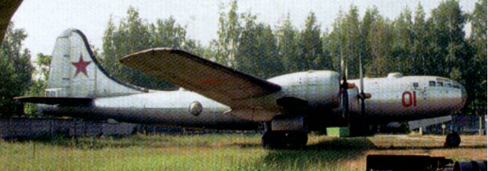
Three examples of the Boeing B-29 arrived in late 1944 (examples of which had made emergency landings in Russia during 1944 in the course of operations against Japan); one being dissected and analysed, and the other two used as crew trainers and evaluation.
The Soviet Union built the Tu-4 by copying them as a virtual exterior clone of the B-29 but with significant interior modifications. It was a heavier aircraft and did not possess either the pressurised tunnel linking the forward to midships crew locations or the integral fuel tankage of the B-29. The first of a 20-aircraft pre-production batch flew on 3 July 1947.
Placed in service in 1948, series production terminated after over 400 aircraft had been delivered in 1952, by which time the Tu-4 was in large scale service with the Soviet DA (Long-Range Aviation), being accorded the NATO reporting name ‘Bull’. Some were used as wingtip-to-wingtip inflight-refuelling tankers, others as conventional HDU-equipped tankers.
It is reported that about 1200 were built.
The type was exported to China where some were re-engined with Ivchenko AI-20 turboprops and were sporadically used into the 1990s as AEW and drone launching platforms.
Engines: 4 x ASh-90, 1705kW Max take-off weight: 61300 kg / 135144 lb Empty weight: 35000 kg / 77162 lb Wingspan: 43.1 m / 141 ft 5 in Length: 30.2 m / 99 ft 1 in Height: 8.5 m / 28 ft 11 in Wing area: 161.5 sq.m / 1738.37 sq ft Max. speed: 570 km/h / 354 mph Ceiling: 11000 m / 36100 ft Range w/max.payload: 5000 km / 3107 miles Crew: 11 Armament: 5 x 23mm cannons Bombload: 5000kg
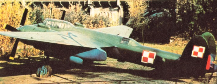
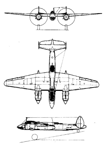
The origin of the Tupolev Tu-2 lay in the ANT-58, ANT-59 and ANT-60 light bomber prototypes that came from the design bureau of Andrei N. Tupolev during 1938-40. Powered by two 1044kW Mikulin AM-37 V-12 engines, the ANT-58 made its first flight on 29 January 1941.
The ANT-60 was re-engined with the big and powerful 1104kW M-82 radials because of the relative unreliability of the AM-37s. The result was the definitive Tu-2 bomber that was to see service with the V-VS during the last year of World War II and well into the 1950s.
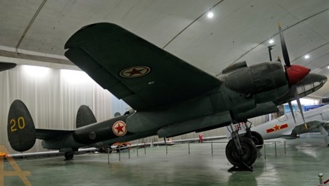
Soviet industry was still in a state of upheaval following the years of 1941-2, when the German army struck deep into Belorussia and the Ukraine. The Tu-2 was too complicated an aircraft for the conditions prevailing, and after many months in which the Tu-2 was modified and simplified for the mass production lines, the Tu-2S (Seriinyi, or series) appeared, flying for the first time on 26 August 1943. A small number of Tu-2s had previously been passed to front line regiments in September 1942, where their performance, armament and bombload had received general enthusiasm.
By January 1944 the first production Tu-2 and Tu-2S bombers had been passed to the regiments of the V-VS, but it was not until June of that year that Tu-2s saw action on a large scale. The sector was the Karelian (Finnish) front in the north where the V-VS forces, under the overall command of General A.A. Novikov, numbered 757 aircraft of the 13th VA (Air Army), the V-VS KBF (Red Banner Baltic Fleet) and the 2nd GVIAK (guards fighter corps). Of the 249 Tu-2 and Petlyakov Pe-2 light bombers in the Soviet order of battle, many came under Colonel I.P. Skok’s 334th Bomber Air Division which subsequently received a citation for its work. Reconnaissance work was now being carried out by Tu-2D and Tu-2R aircraft with modified mainplanes, nose glazing, and capacity for vertical and oblique cameras. Wartime production of the Tupolev Tu-2 and its sub-types amounted to 1,111. As a bomber it did not come into its own until the autumn of 1944. However, as German resistance stiffened on nearing the eastern borders of the Reich V-VS bombers, including Tupolev Tu-2s, were called up to attack strongpoints at Kustrin and other fortified ports and cities. September 1945 saw many Tu-2s in action against the Japanese Kwantung Army in Manchuria before the final surrender.
Tu-2
Tupolev was awarded a Stalin Prize for his Tu 2 medium bomber, the only wholly new Soviet wartime aircraft to go into production.
Tu-2S Engines: 2 x ASh-82FNV, 1380kW Max take-off weight: 11360 kg / 25045 lb Empty weight: 7474 kg / 16477 lb Wingspan: 18.86 m / 62 ft 11 in Length: 13.8 m / 45 ft 3 in Height: 4.55 m / 15 ft 11 in Wing area: 48.8 sq.m / 525.28 sq ft Max. speed: 550 km/h / 342 mph Ceiling: 9500 m / 31150 ft Range: 1400 km / 870 miles Crew: 4 Armament: 2 x 20mm cannons, 3 x 12.7mm machine-guns Bombload: 4000kg
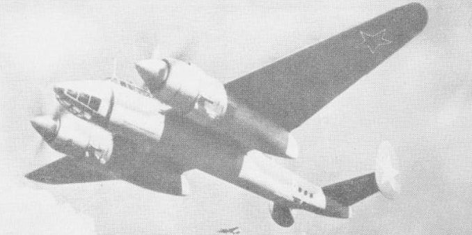
The two ANT-40 light bomber prototypes of Andrei N. Tupolev’s design bureau first flew in October 1934. The all-metal construction, enclosed cockpit and retractable landing gear were then comparatively novel features. The ANT-40’s maximum speed of 325km/h at operating height was faster than the biplane interceptor fighters that equipped most of the peacetime air forces.
Tupolev SB-2 Article
Entering production in 1936, the initial production version as selected for export and service with the V-VS was based on the second prototype, and was known as the Tupolev SB-2 (skorostnoi bombardirovshchik, or fast bomber). The engines were two 830 hp / 619kW licence-built Hispano-Suiza 12Ybr, termed M-34 by Soviet industry, and initially they were fitted with two-bladed fixed-pitch propellers.
An aircraft of this type secured an official FAI record in 1937 for carrying a 1000 kg / 2200 lb payload to an altitude of 40,177 ft.
The first SB-2s were passed to the V-VS’s bomber aviation regiments in February 1936, and in October of that year the first of 210 were transferred with Soviet crews to Spain to fight on the side of the Republican air force against the insurgent Nationalists.
The SB-2 was the first Soviet warplane delivered to the Republicans, arriving from October 1936 in an effort to provide an offensive type which could take the air war to the advancing Nationalists. The variant delivered was the initial SB-2 production model powered by M-100 or 641 kW (860-hp) M-100A inlines driving fixed or variable pitch propellers respectively. Estimates for the number of SB-2s delivered vary from 93 to 210, and these aircraft were amongst the best fielded by the Republicans: their performance and defensive firepower allowed most Nationalist fighters to be outrun or outfought. Some 19 operational SB-2 bombers fell into Nationalist hands at the end of the war, and claims on the type amounted to 14 by the Nationalists, a similar number by the Germans, and 48 by the Italians.
Over Spain the performance of the SB-2 caused considerable concern to the Nationalist fighter units which were equipped with Heinkel He-51 and Fiat CR.32 biplanes, and the urgent call went out for fighters of better speed and climb properties.
The production of the SB-2 bomber and the conversion of the units required the development of a training model that would facilitate the preparation of the crews. This need was solved in 1937 with the installation of a second flight control in the navigator’s position in an SB-2M-100A, but the results of the tests showed that this decision made the navigator’s work more complex and worsened the aerodynamics of the model.
At the time SB-2s were passed to the Chinese Nationalist air force to fight aganst the Japanese, and to Czechoslovakia, where the type went into licensed manufacture as the B.71 bomber.
1934 Avia development was helped engineer A. A. Archangelskij from the ANT 40.2 SB – 2 (Skorostnyj Bombardirovščik). The Czechoslovak Air Force had 60 of these aircraft and one at a research institute. Because all three Aeroplane Works within a range of German bombers were, a new plant was built at the village of Kunovice in South Moravia. Two batches of the B-71 bomber – 40 and 26 machines respectively. 30 SB-2s were purchased by the Czechoslovak Republic from the Soviet Union and in 1936 also their licence. Serial production started at Avia and by the German occupation not a single was finished, the unfinished aircraft were completed by the Germans. Avia Works built forty-five that were used by Luftwaffe or sent to Bulgaria. The B-71 Katyushkas were powered by Czech-made 680 Avia-Hispano Suiza engines and were able to accommodate the bombload of 600 kg under their wings.
The Avia-built B-71 were fitted with a new tubular radiators and gained 15 kph. The idea was copied by the Soviets and brought into use in the SB-3. After the German occupation the B-71s were converted to target towing configuration.
Avia B-71
In general the SB-2 performed well until faced with sterner fighter opposition, which occurred over Spain in 1938 and in particular over Finland during the Winter War of 1939-40, when many were shot down. Steps were taken to improve performance by installing the 641kW M-100A engine with variable-pitch propellers. Increased fuel capacity and two 716kW M-103 engines were installed in the Tupolev SB-2bis, the performance of which was improved by three-bladed VISh-22 propellers.
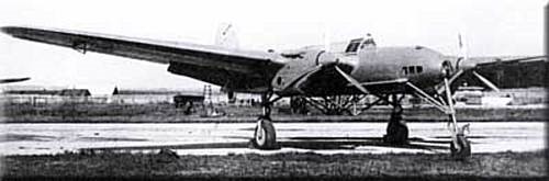
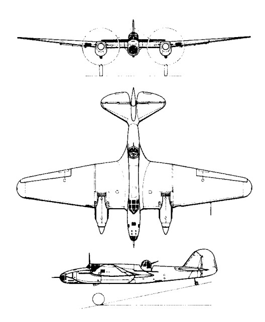
The study of the 3-wheeled undercarriage on a twin-engined aircraft, nicknamed “pterodactyl”, was carried out in 1940. Using a special frame under the center section the pilot, Mark Galley, repeatedly landed the aircraft with a vertical speed of up to 4.8 m / s. The landing gear was fully tested. For study of the “shimmy” phenomenon the ran over a log put across the runway. The original size of the front wheel was 470×210 mm, but changed to 600×250 mm.
SB “Pterodactyl”
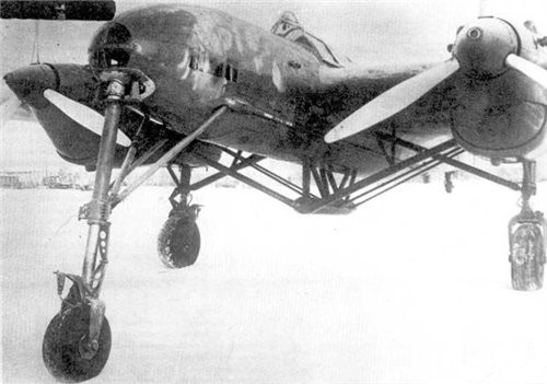
The front wheel was 4.65 m from the center of gravity and the main struts moved back beyond the center of gravity 520 mm, the wheels remained the same – 900×300 mm.
SB “Pterodactyl”
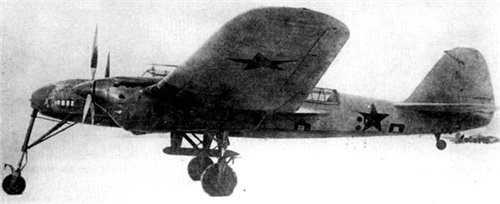
A frame was used to rearrange the main undercarriage in order to determine their optimal location. The aircraft was tested with a flight weight of 6000 kg, the wing load was 106 kg/sq.m and flight speeds up to 220 – 230 km/hr. Landing speed with flaps was 140 – 150 km / h, without flaps 190 km/h.
SB “Pterodactyl”
Tests were summarized and published in February 1941, turned out to be very popular. It is believed that the research results were useful in developing a new generation of Soviet aircraft with a front support wheel.
The PS-41 was a transport variant with a ‘solid’ nose and gun positions eliminated.
In addition to the PS-40 and PS-41 transport versions the SB-RK (Arkhangelskii Ar-2) was a modified SB-2bis dive-bomber with reduced wing area and powered by two supercharged M-105R engines. The SB-2’s record as a day bomber came to an abrupt end during the fierce fighting following the German invasion of the USSR on 22 June 1941. Those that were not destroyed on the ground ventured into the air on numerous missions over the front line, and paid a heavy price to the Luftwaffe’s Messerschmitt Bf 109F fighters. Thereafter the SB-2 and SB-2bis bombers were relegated to night work with the V-VS and the Soviet naval air arm.
Production amounted to 6,967 of all marks.
Variant: Tupolev SB-RK / Arjanguelsky Ar-2 Arjanguelsky SB-B Arjanguelsky USB
SB-2 Three-seat light/medium bomber Span: 20.33m (66ft 8.5 in) Length: 12.57m (41ft 2.75in) Powerplant: 2 x Klimov M-100, 559kW (750 hp) Armament: 4×7.62-mm (0.3-in) mg Bombload: 1000 kg (2,205 lb) Max T/O weight: 5628 kg (12,407 lb) Max speed: 244 mph at 17,060 ft Operational range: 777 miles
SB-2bis Engine: 2 x M-100 Max take-off weight: 5732 kg / 12637 lb Empty weight: 4060 kg / 8951 lb Wingspan: 20.3 m / 67 ft 7 in Length: 12.7 m / 42 ft 8 in Wing area: 52.0 sq.m / 559.72 sq ft Max. speed: 420 km/h / 261 mph Cruise speed: 360 km/h / 224 mph Ceiling: 6600 m / 21650 ft Range: 1600 km / 994 miles Range w/max.payload: 1000 km / 621 miles Crew: 3 Armament: 4 x 12.7mm machine-guns Bombload: 1500kg
SB-2bis Engine: 2 x M-103, 990 hp Wingspan: 70 ft 6 in Length: 41 ft 6 in Max take-off weight: 14,330 lb Empty weight: 9436 lb Max. speed: 280 mph at 16,400 ft Cruise speed: 360 km/h / 224 mph Service ceiling: 27,890 ft Range: 1430 miles Crew: 3 Armament: 4 x 7.62mm machine-guns Bombload: 1320 lb
Designed and built by the Swedish Army Aircraft Factory, as a trainer for the Swedish airforce and first flown in June 1919. Only 28 were built before the type was retired in the 1920s.
The association between France and Germany that has produced the Transall began when the German aircraft industry built the Nord 2501 Noratlas under licence for the Luftwaffe. The successful co-operation between the Weserflugzeugbau GmbH and Nord Aviation on the Noratlas programme led to both companies studying a follow-on project for this old-fashioned twin-boom piston-powered medium transport. The “Transporter-Allianz” was formed in January 1958 by the participating companies, Transall being an abbreviation of the name, while the letter “C” stood for “Cargo” and the figure “160” for the equivalent wing area of 160 square metres. The joint team designed a tactical cargo and troop transport in the 50-ton category to fulfil the joint requirements of the French and German forces, with the capability of hauling a 17,600-1b (8 000-kg) payload out of semi-prepared fields over a radius of 750 miles (1200 km) without refuelling.
After several individual concepts had been studied separately in both countries, the Transporter Allianz concentrated on a shoulder wing design with two Rolls-Royce Tyne 20 Mk 22 turboprops of 6,100 eshp each, with a rear loading ramp and a kneeling landing gear to lower the fuselage for loading. According to the bi-national contracts signed in December 1959 and March 1960, the R & D costs were to be divided equally between France and the Federal Republic of Germany while each country would pay for the number of aircraft ordered for its specific needs, and final assembly lines would be established in each country.
The first prototype, the C-160 V 1, was assembled in France and made its maiden flight on 25 February 1963 at Villaroche, the V2, assembled by VFW Fokker, following exactly three months later at Lernwerder; the V3 flew on 19 February 1964 in Hamburg, (two separate assembly lines having been set up in Germany by MBB and VFW). Also in 1964, the airframes for static and dynamic tests were completed. An additional six pre-series aircraft were built before production started, with the first delivery on 2 August 1967. France had meanwhile ordered 50 Transalls (C- 1 60F), Germany ordered 110 (C-160D), 20 of these being later passed to the Turkish Air Force (as C-160T), and the Republic of South Africa bought another nine (C-160Z). The six pre-series aircraft were divided between France and Germany.
As far as the production breakdown is concerned, Nord Aviation was responsible for the wings and engine nacelles, Hamburger Flugzeugbau (HFB) built the front and rear sections of the fuselage and Vereinigte Flugtechnische Werke (VFW) the central fuselage and the horizontal tail surfaces. Some wing parts and the flaps were sub-contracted to Messerschmitt and Siebel ATG while Dornier built the vertical tail surfaces. The Messier-designed landing gear was coproduced with Liebherr-Aerotechnik. Rolls-Royce cooperated with Hispano-Suiza (now a branch of Snecma, France), MAN (later Motoren- und Turbinen-Union, Munich) and FN (Belgium) in manufacturing the Tynes. Ratier-Forest in France produced the big 18-ft (5,49-m) diameter four-bladed de Havilland propellers and Normalair (UK) delivered the pressurisation and air conditioning systems. VFW was the lead company in the programme.
The shape and dimensions of the fuselage were essentially designed to conform with the “International Railway Loading Gauge” over the entire length of the hold. The length of the compartment including the ramp is 56 ft 6 in (17,21 m), the useful width is 10 ft 4 in (3,15 m) and the max useful height 9 ft 9 in (2,98 m). The floor area is 583,9 sq ft (54,25 sq.m), giving a usable volume of 4,940 cu.ft. (140 cu.m).
Thus, a total of 178 Transalls had been produced when the last aeroplane rolled off the assembly line in October 1972. Deliveries totalled 52 C 160F for the Armee de l’Air (four modified as 160P civil night mail transports), 110 160D for the Luftwaffe (20 later transferred to the Turkish air force and 32 stored) and nine 160Z for the South African Air Force.
51+02 LTG-63 Hohn A/B, Dec 1986
The Transall C-160 was designed for flexible payload-range capabilities and stringent mission requirements. These include high gust and manoeuvre loads of 3 g at low level, as well as high static loads on landing gear and structure encountered in rough, semi-prepared field operations. The fuselage is built in three units, with the usable section designed for an operating pressure of 4.7 psi. In the centre section of the fuselage, seven main wing-fuselage frames made of forged and plate components carry the loads from the wing and the landing gear. The fuselage skin is stiffened by extruded Z section stringers. Heavy corrugated aft-fuselage frames in the tailplane take up the forces from the tail unit and the aft upward hinged cargo door.
The wing comprises three major components, a parallel chord centre section to which are bolted two tapered outer panels. The primary structure is a wing torsion box with two shear-web spars to which are attached the leading- and trailing-edge sub-assemblies. The upper and lower wing skin panels are stiffened with longitudinal extruded T-section stringers. Double-slotted flaps, spoilers, airbrakes and ailerons make up the moving surfaces of the wing. The tail unit consists of a three-spar, fully cantilevered horizontal stabiliser and a three-spar fin torsion box with stiffened skin construction. Elevator and rudder are of the same conventional construction. The dorsal fin consists of aluminium sandwich flat panels.
The main landing gear has eight wheels, with two tandem pairs of wheels on each side. Together with low pressure (55 psi) tubeless tyres sized 15.00-16, the resulting single wheel loads provide the aircraft with an excellent ability for operations from semi-prepared or unprepared strips. The twin-wheel low pressure (45 psi) nose gear is hydraulically steerable through 55 deg each side. To ease loading procedures from ground or low levels, the main landing gear may be kneeled, ie, partially retracted, thus changing the ramp slope-angle with respect to the cargo compartment floor-line. The system is operated by special built-in shock absorber-jack cylinders through power supplied by one of the engines, APU or hand pump.
Aerospatiale, MBB and VFW, decided in May 1976 to reinstate the production of the twin-turboprop Transall C-160 tactical transport. The French Armee de l’Air was at that time showing interest in buying 25-30 aircraft, and an industrial agreement was signed on 29 October 1976, it being then estimated that an order backlog of at least 75 aircraft would be needed to make the new programme an economic worthwhile enterprise.
The French Government therefore decided in July 1977 to approve the launching of the second series of the Transall C160 and ordered 25 aircraft for the Armee de l’Air. The only large aeroplane in Europe to be built on a re-established production line, having been designed in the mid-‘fifties.
Under the new industrial agreement for the second series, rather different arrangements have been made, there being no main contractor. Aerospatiale and the two German manufacturers VFW and MBB – all three original members of the Transporter-Allianz having changed their status as a result of mergers in the last decade – share the work on a fifty-fifty basis, now with a single assembly line at Toulouse. Aerospatiale is building the wings, fuselage doors, emergency exits and engine nacelles. The manufacture of the front and rear fuselage sections including the loading ramp and the dorsal fin is undertaken by MBB. VFW (itself now in process of merging with MBB) produces the centre fuselage, main landing gear fairings and all main tail surfaces. Unchanged from the previous arrangement is the share of production of the Tynes, jointly manufactured by Rolls-Royce, Snecma, MTU and FN. As in the Airbus programme, all the major airframe parts are airlifted from the manufacturing centres in Germany to Toulouse in a Super Guppy transport, for final assembly and flight testing.
No major modifications have been incorporated in the C160 design, but the list of changes in many details is quite impressive. The forward side loading door is deleted and the deicing system improved. Minor changes affect the landing gear as well as the cargo handling system. New bonding techniques are applied and corrosion protection is improved. Structural provisions are made for additional fuel tanks in the wing centre section to allow for a total of 6,170 Imp gal (28 050 lt) instead of 4,190 Imp gal (9 050 lt) with the original outer wing tanks only. This not only provides for an extended range of 4,780 nm (8 854 km) for ferry flights, but also sufficient fuel capacity for aerial refuelling tasks which are new for the aircraft. Ten of the 25 new Transalls are to be equipped with hose and drogue in-flight re-fuelling systems in the lengthened port main landing gear fairing, to serve as tankers; another five will have provision for this equipment and can be rapidly adapted to the tanker role if required. All the 25 aircraft can be refuelled in flight, using a 13 ft 1.5 in (4-m) long probe installed above and behind the flight deck.
The flight deck is designed for operations by a crew of three. As an optional extra it accommodates a swivelling seat for special tasks. The exceptionally spacious flight deck also has two berths in addition to the crew seats. The field of vision from the pilot’s position is 243 degrees.
Although the Transall C-160 is specially designed for carrying troops and cargo, it is also capable of fulfilling a variety of other missions. With a maximum payload of 3 5,270 lb (16 000 kg), the range is 1,000 mls (1850 km), increasing to 2,750 mls (5 100 km) for a payload of 17,640 lb (8 000 kg); the maximum range for ferry flights is 4,780 mls (8 850 km). Fuel consumption with both engines operating varies from 2, 100 lb to 2,755 lb (950 kg to 1250 kg) per hr and the manufacturer claims that this figure is about 30 per cent better than its competitors on a given mission.
As a cargo transport, a variety of heavy or outsized loads can be carried. This includes most military vehicles, airmobile tanks, armoured cars, missiles, partially disassembled helicopters and aircraft. An automatic latching system and easily adjustable rails and rollers permit quick-loading of pallets in standard sizes such as 88 in x 125 in (2,24 m x 3,18 m), 88 in x 108 in (2,24 m x 2,74 m), etc, standard inter-model 8 ft x 8 ft (2,44 m x 2,44 m) containers as used on trucks, railways, ships and wide-body aircraft, or 12 LD3 containers. Reinforced vehicle treadways allow for carrying vehicles with axle loads of up to 11,023 lb (5 000 kg) and freight loads of up to 205 lb/sq ft (1000 kg/sq.m). Air dropping of heavy loads (up to 17,640 lb/8000 kg single loads) is possible either by gravity release or parachute extraction.
Deliveries of the Transall C-160 (Second Series), which first flew on April 9, 1981, were completed in 1985. The sole military customer was the French Air Force, which ordered 25 with updated avionics, a strengthened wing centre section incorporating an additional fuel tank, and in-flight refuelling capability. Ten are equipped as dual-role single-point tankers, and five more have the necessary modifications to allow rapid conversion to the tanker role. In 1982 four additional aircraft were ordered for the French Air Force, two as secure communications relay platforms known as C-160A Astarte for the nuclear deterrent force from 1987, and two Gabriel electronic intelligence aircraft.
C.160 Type: tactical transport Crew: 3 Engines: two 6,l00-ehp (4,549-kW) Rolls-Royce Tyne RTy.20 Mk 22 turboprops Props: Ratier Forest built BAe Dynamics 4 blade constant speed feathering, reversing, 21 ft 4 in (6,50 m) dia Maximum speed 319 mph (513 kph) at 16,000 ft (4,875 m) Cruise speed: 510 kph Initial climb rate 1,300 ft (396 m) per minute Single engined climb rate, 300 ft/min (1,51 m/sec) Service ceiling 27,000 ft (8,230 m) Single engined ceiling, 10,000 ft (3 050 m) Range 1,150 miles (1,853 km) with max payload Range 5100 km with 8,000 kg Max ferry range, 4,780 nm (8 858 km) Empty weight 63,935 lb (29,000 kg) Maximum take-off 112,435 lb (51,000kg) Wing span 131 ft 3 in (40.00 m) Length 106 ft 3.5 in (32.4 m) Height 38 ft 2.75 in (11.65 m) Undercarriage track, 16 ft 9 in (5,10 m) Wheelbase, 34 ft 4.5 in (10,48 m) Wing area 1,722.3 sq ft (160 sq.m) Payload: 93 troops, or 88 paratroops, or 62 litters and four attendants, or 35,273 lb (16,000 kg) of freight Air refuel: Yes T/O run: 715 m Ldg run: 550 m Basic fuel capacity, 4,190 Imp gal (19050 lt); optional wing centre section tanks for 1,980 Imp gal (9 000 lt)
C-160 Srs.2 Engines: 2 x Rolls-Royce/Snecma/MTU Tyne RTy 20 Mk 22 turboprops, take-off rating 6,100 eshp each at SL, ISA, and 5,950 eshp at SL, ISA + 22 deg C; water/methanol injection system Fuel capacity, outer wings only, 4,190 Imp gal (19 050 lt), total with centre wing tanks, 6,170 Imp gal (28 050 lt) Props: four-bladed Ratier-Forest (under HSD-licence) fully feathering and reversible Prop diameter, 18 ft 0.5 in (5,50 m) Garrett AiResearch GTCP 85-160 APU, max continuous rating, 200 shp Max operating, speed, VMO 277 kts (513 km/h) CAS MMO, M = 0.64 Initial rate of climb (at 108,355 lb/49 150 kg, SL, ISA); 1,360 ft/min (6,9 m/sec) Max operating altitude, 30,000 ft (9 145 m) Take-off run (at 108,355 lb/49 150 kg, SL, ISA), 2,100 ft (6 400 m) FAR take-off field length, 5,600 ft (1707m) Landing run (MLW, SL, ISA), 1,400 ft (427 m) FAR landing field length, 4,950 ft (1509 m) Max range (at MTOW) including reserves for 5% initial fuel + 30 min: 1,000 nm (1850 km) with max payload of 35,273 lb (16 000 kg), 2,750 nm (5 094 km) with payload of 17,637 lb (8 000 kg) Max range with outer wing fuel only, 3,430 nm (6 353 km), with centre section tanks, 4,780 nm (8 854 km). Max take-off weight, 112,434 lb (51000 kg) Max landing weight, 103,615 lb (47 000 kg) Max zero fuel weight (2.5 g factor), 99,206 lb (45 000 kg), (3.0 g factor), 81,570 lb (37 000 kg) Minimum operating weight empty, 61,728 lb (28 000 kg) (plus 440 lb/200 kg for centre wing tanks) Span, 131 ft 3 in (40,00 m) Length, 106 ft 3.5 in (32,40 m) Height, 28 ft 2.5 in (11,65 m) Wing area, 1,722 sq ft (160,00 sq.m) Accommodation: Flight crew of three Cabin floor area, 584 sq ft (54,25 sq.m) Cabin volume, 4,944 cu ft (140,00 cu.m)
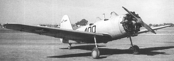
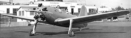
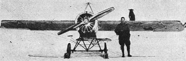
Under the trade name Aeromold, the Timm Aircraft Corporation developed a special form of construction using bonded plywood. To validate the new structural medium and ultimately to provide a commercial outlet, the company produced its private-venture S-160 / PT-160K (747) cantilever low-wing trainer with tandem accommodation in open cockpits and fixed tailwheel landing gear whose main units looked very spartan with their unfaired tubular metal legs. Designed by Otto Timm the sole S-160, NX15593, had an optional cockpit canopy.
Timm S-160 NX15593
Don Mitchell went to the new Timm Aircraft factory in Van Nuys, where he helped with the molding of the fuselage of the S-160, a plastic-bonded wood basic trainer developed for use by the U.S. Navy and U.S. Army Air Corps. Mitchell later assisted the Civil Aeronautics Administration when the time came to perform the static tests of the aircraft. It passed with flying colours and later became, in April 1941, one of the first if not the very first ever plastic-bonded aircraft to receive an American Approved Type Certificate.
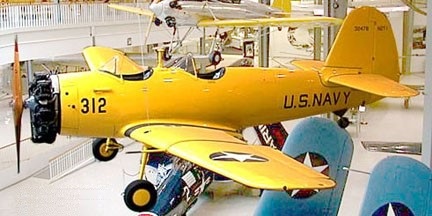
This prototype was developed into the PT-175K (750 2-573) for the civil market, and 262 of a modified variant with the Continental R-670 radial engine were ordered by the US Navy with the designation N2T-1, the aircraft being delivered in three batches during the course of 1943. The one prototype was NX15593 and 262 to the USN as N2T-1 were 41-05875 & 41-05876, 41-32387-32636, and 41-39182-39191.
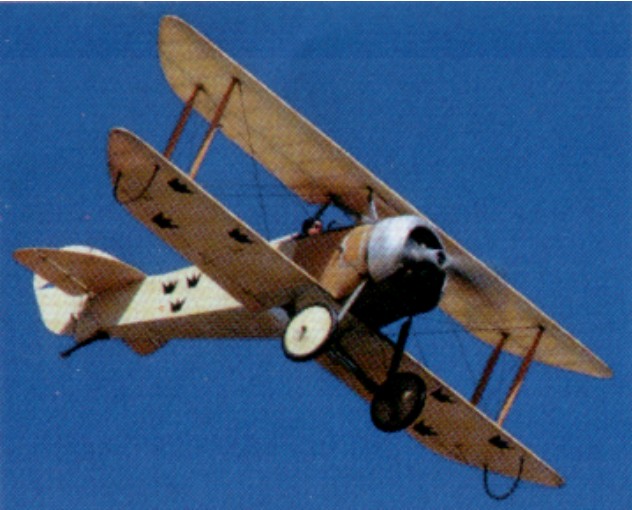
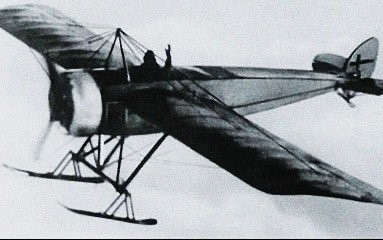
The Thulin K was based on the Nieuport IVG which they’d imported.
Nils Rodéhn
Eighteen Thulin Ks were built in 1917, sixteen going to the Dutch Army in 1920.
Engine: Thulin A, 105 hp Wingspan: 29 ft 9 in Length: 21 ft 4 in Max speed: 93 mph Cruise: 81 mph Landing speed: 53 mph Time to 3300 ft: 4 min Ceiling: 20,000 ft
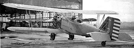
The Thomas-Morse O-19 two-seat observation aircraft was a 1929 improved version of XO-6 design.
The prototype XO-19, 28-400, first flew in April 1929 powered with a 450hp P&W R-1340-3. Only the one XO-19 was built, later becoming the XO-19B. Converted in 1930, it was for McCook Field tests as P-598.
Two O-19 were built in 1929 for service tests, powered with the 500hp R-1340-9 engine. They became O-20 28-401 and -21 29-369.
The sole O-19A from 1929, 29-370, featured a modified fuel tank.
The O-19B of 1930 was the first production version, with new cockpits. Seventy were built, 30-90 to 30-159, the first converted to Y1O-33.
Thomas-Morse O-19B
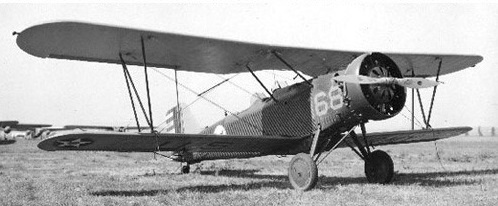
Seventy-one O-19C from 1931 were built by Consolidated Co: 31-278 to 31-348. They featured a ring cowling and tail wheel. One O-19C, 31-279, was converted in 1931 as staff transport for the Secretary of War.
Thomas-Morse O-19C
Thirty of the 1932 O-19E were built: 31-523 to 31-552.
Thomas-Morse O-19E
The Thomas-Morse O-20 of 1929 was the O-19 powered with a 525hp P&W R-1690-1. One was built as the YO-20 (28-402), plus one re-designated from O-19 (28-401).
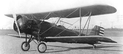
The Thomas-Morse O-21 was the O-19 with a 600hp Curtiss H-1640 Chieftain engine.
One XO-21 was built, 28-403, and one O-21 re-designated from O-19, 29-369, in 1929.
Thomas-Morse XO-21 28-403
The 1929 XO-21A was XO-21 refitted with a 525hp Wright R-1750-1 engine.
The Thomas-Morse O-23 of 1929 was an O-19 with a 600hp Curtiss GV-1570-29 Conqueror engine. One was built as YO-23 (29-352).
Development/production of these continued after Thomas-Morse had been acquired in 1929 by Consolidated Aircraft Corporation.
O-19B Engine: P&W R-1340-7, 450hp Wingspan: 39’9″ Wing area: 348 sq.ft Length: 28’4″ Height: 10 ft Empty weight: 2732 lb Gross weight: 3910 lb Max weight: 4233 lb Fuel capacity: 80+40 USG Useful load: 1078 lb Max speed: 139 mph at SL / 135 mph at 10,000 ft Cruise speed: 121 mph Landing speed: 57 mph Service ceiling: 20,500 ft ROC: 1780 fpm Tme to 10,000 ft: 11 min Range: 397 mi normal / 462 mi max Seats: 2
O-19C Engine: R-1340-7, 450hp Wingspan: 39 ft 9 in Wing area: 348 sq.ft Length: 29 ft Height: 10 ft 0 in Empty weight: 2769 lb Gross weight: 3921 lb Max weight: 4269 lb Fuel capacity: 76+39 USG Top speed: 143 mph at SL / 137 mph at 10,000 ft Cruise speed: 124 mph Landing speed: 57 mph Service ceiling: 20,000 ft Absolute ceiling: 21,800 ft ROC: 1810 fpm Climb to 10,000 ft: 11 min Range: 377 mi normal / 436 mi max
O-19E Engine: R-1340-15, 575hp at 5000 ft Wingspan: 40’0″ Wing area: 359 sq.ft Length: 28’10” Height: 10 ft 4 in Empty weight: 2774 lb Gross weight: 3938 lb Max weight: 4275 lb Fuel capacity: 80+40 USG Top speed: 156 mph at 5000 ft / 153 mph at 10,000 ft Cruise speed: 136 mph Landing speed: 57 mph Service ceiling: 23,500 ft Climb to 10,000 ft: 10.7 min Range: 473 mi
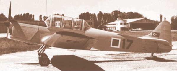
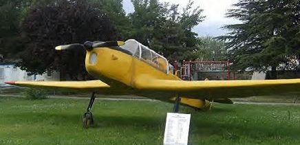
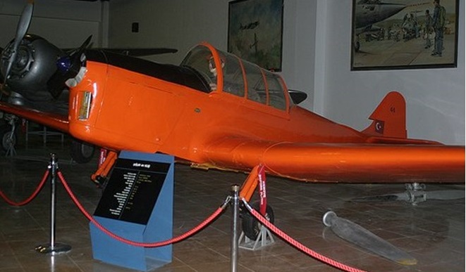
MKEK 4 Ugur Engine: DH Gipsy Major 10 Mk.I, 145 hp Wing span: 31 ft 2.5 in / 9.50 m Wing area: 171 sq.ft Length: 24 ft 7.25 in Empty weight: 1465 lb Loaded weight: 2045 lb Max speed: 135 mph Cruise: 110 mph ROC: 800 fpm Service ceiling: 16,000 ft Range: 300 mi Seats: 2 tandem
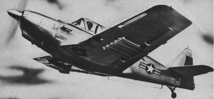
Pappy Gunn landed a post-war job as technical advisor to the Philippine Air Force, and leaked word that the PAF just might be in the market for a tiny tandem trainer that could mount a pair of machine guns in the wing to go shoot up rebellious natives or whatever. Robert McCullough, who was then president of TEMCO, asked the sales department whether a commercial version of such a plane would find a market, and when they said yes, the engineers, under Dave Tacke, got busy and hand-built a modification of a standard Swift into what was called the TE-1A.
The only changes in this initial prototype were to install tandem instead of side-by-side seats, tandem controls, a new canopy and a squared off rudder, much like that of the T-6. The sirnilarity was not accidental TEMCO was originally founded to hold together a postwar production team of outstanding skill, and more than 90% of the employees had worked for North American building T-6s and P-51 Mustangs. To come up with something in a hurry, the prototype trainer was designed originally as a converted Swift, which was already in production at TEMCO since Globe went bankrupt.
The TE-1A had tandem cockpits; 24v electrics, raised horizontal tail, strengthened wing with added fillets, and improved landing gear. In late 1948 the first TE-1A prototype was ready to fly, behind a 125-horsepower Continental, when word came that the USAF planned a competition in early 1949 for a new primary basic trainer. There was no time for a major redesign, so they cleaned up the canopy and sent the ship off to Wright Field to compete against the Fairchild T-31 and the Beech T-34, with Fairchild winning that round. Forgetting the Air Force’s interest, TEMCO decided to press on with the Buckaroo as a COIN aircraft for smaller foreign governments, brought in a noted small-plane engineer, H.G. Erickson, and went to work on a complete new program to come up with a really first class plane with no restrictions.
Scrapping the original TE-1A design, a whole new aircraft was evolved, still designated the TE-1A, of the same general weight, type, and configuration, but designed to military standards. Starting from scratch with a plaster and steel mockup, they, designed a brand new fuselage and wing center section, bulging the rear fuselage slightly, raising the deck, lengthening the nose and adding three inch’s to the overall length. Outer wing panels were stressed to 9 G’s and the tips squared off. The only vestige of its Swift lineage was to leave in the leading edge slot assembly, which gave more positive control at low airspeed.
About the only parts of the original airframe left were the cowl and canopy, neither of which survived the initial flight test stage. The canopy became a three-piece sliding type with magnesium framework, and the cowl was redesigned to provide downdraft rather than updraft cooling.
Other changes included a panel redesign to conform to the Air Force Standard Cockpit layout that originated with the T-6 Texan in World War 11, addition of an Aeromatic Model F-200H propeller with altitude control, a 24-voll electrical system, and a single fuel tank of 27.6 gallon capacity.
The finished product looked so good that in late 1949 TEMCO tooled up for limited production of 10 items, with 145-horsepower Continentals’ but just then they heard through the grapevine that the Air Force actually wanted to buy three YT-35s, as they were then called, for a new evaluation at Randolph AFB (the earlier USAF contract had been cancelled). So the horsepower went from 145 to 165 and the Buckaroo went to the lists as the TE-1B.
The official policy line was no more taildraggers in the Air Force.
The Israeli Air Force got the first TE-IA, N90080, in June, 1950, with machine guns and ten 2.75-inch rockets, one TE-1A went to the Greek Air Force, while the original three TE-1Bs, designated YT-35 Buckaroos, went to the Air Force the next month. Saudi Arabia took delivery of ten more Buckaroos, 53-4465 to 53-4474. Saudi Arabia installed two .30 wing guns and ten underwing rocket launchers.
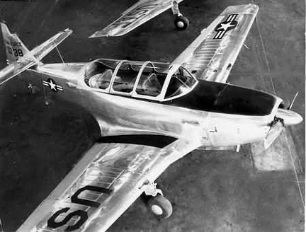
Temco T-35
The three USAF TE-1Bs, 50-738 to 50-740, were finally shipped to San Marcos AFB as instrument trainers for Field Force Liaison Pilots, and ten months later were returned to TEMCO for factory overhaul preparatory to still another round of evaluation tests at Goodfellow AFB, against the YT-34, with a T-6 Texan serving as control ship. Thus it was that Beech beat out TEMCO and the three TE-1Bs (or YT-35s) went up for sale as military surplus.
A Jack Hardwick picked up the three Buckaroos from the government and eventually disposed of them.
YT-35 Engine: 165 h.p. Franklin 6A4-165-B3 Span: 29 ft. 2 in Weight: 1,975 lb Max. Speed: 156 mph
T-35 Buckaroo Engine: Franklin 6A-165-B3, 165 hp Wingspan: 29′ 10″ Length: 21′ 8″ Useful load: 620 lb Max speed: 150 mph Cruise speed: 142 mph Stall: 56 mph Range: 550 mi Seats: 2 Tandem Undercarriage: retractable