1997: Avenida Ayrton Senna 2541 Aeroporto de Jacarepagua, Hanger 10 Rio de Janeiro, RJ Brazil.
LSA builder
1997: Avenida Ayrton Senna 2541 Aeroporto de Jacarepagua, Hanger 10 Rio de Janeiro, RJ Brazil.
LSA builder
The Mistral two axis was a side by side two seat single engined flex wing aircraft. Wing has swept back leading and trailing edges, and tapering chord; no tail, canard wing. Pitch control by fully flying canard; yaw control by tip rud¬ders; no separate roll control; control inputs through stick for pitch/yaw. Wing braced from above by kingpost and cables, front below by cables; wing profile based on Pterodactyl; 60% double surface. Undercar¬riage has three wheels in tricycle formation; bungee suspension on all wheels. No ground steering. No brakes. Aluminium tube framework, without pod. Engine mounted below wing driving pusher propeller. Drawn aluminium tubing manufactured to British HT30TF specification. Terylene sailcloth wing.
The Mistral was in concept a two seater Pterodactyl, produced with Pterodactyl director Jack McCornack’s bles¬sing. Much of the design was scaled up from the American machine, including the wing profile, which is Pterodactyl derived.
Though neither fast nor elegant, the Mistral did prove quite robust and offered full dual controls, a combination which appealed to training schools. A total of eight two axis machines were built, of which the first three used Cuyuna 430R engines. Later aircraft were fitted with a Robin EC44, which is considerably more powerful.
The Mistral three axis is the same as the two axis Mistral except: conven¬tional three axis control (unconventional three axis optional). Roll control by spoilers; control inputs through stick for pitchlroll (pitch/yaw optional) and pedals for yaw (roll optional).
The original idea behind the three axis Mistral was to make the aircraft suitable for crop spraying, but though test pilot Graharn Andrews did extensive trials with spraying equipment, in fact no aircraft were ever sold for agricultural purposes.
Three aircraft were produced with three-¬axis control, of which two were conventional¬ly arranged, and the third had yaw and roll controls reversed, with the stick operating the rudders and pedals controlling the spoilers. All three aircraft used the Robin EC44 engine.
Two axis
Engine: Cuyuna 430R, 30 hp.
Propeller diameter 54 inch, 1.37 m.
Reduction ratio 2.0/1.
Power per unit area 0.12 hp/sq.ft, 1.3 hp/sq.m.
Fuel capacity 4.8 US gal, 4.0 Imp gal, 18.2 litre.
Empty weight 285 lb, 129kg.
Max take off weight 685 lb, 311kg.
Payload 400 lb, 182kg.
Max wing loading 2.74 lb/sq.ft, 13.4 kg/sq.m.
Max power loading 22.8 lb/hp, 10.4kg/hp.
Length overall 14.3 ft, 4.36 m.
Height overall 11.0ft, 3.35m.
Wing span 40.0ft, 12.19m.
Chord at root 6.6 ft, 2.01 m.
Chord at tip 5.5ft, 1.68m.
Dihedral 3 deg
Sweepback 10 deg approx.
Canard span 7.0ft, 2.13m.
Canard chord 1.5 ft, 0.46 m.
Total wing area 261 sq.ft, 24.2 sq.m.
Main wing area 250 sq.ft, 23.2 sq.m.
Canard area 11 sq.ft, 1.0 sq.m.
Total rudder area 6.0 sq.ft, 0.56 sq.m.
Wing aspect ratio 6.6/1.
Wheel track 7.0 ft, 2.13 m.
Wheelbase 7.0 ft, 2.13 m.
Nosewheel diameter overall 15 inch, 38 cm.
Main wheels diameter overall 18 inch, 46 cm.
Skis: standard adult skis, length reduced to 3 ft, 0.91 m.
Three axis
Engine: Robin EC44, 40 hp at 6000 rpm.
Propeller diameter 54 inch, 1.37 m.
Toothed belt reduction, ratio 2.3/1.
Max static thrust 280 lb, 127 kg.
Power per unit area 0.16hp/sq.ft, 1.7 hp/sq.m.
Fuel capacity 4.8 US gal, 4.0 Imp gal, 18.2 litre.
Empty weight 285 lb, 129kg.
Max take off weight 685 lb, 311kg.
Payload 400 lb, 182kg.
Max wing loading 2.74 lb/sq.ft, 13.4 kg/sq.m.
Max power loading 17.1 lb/hp, 7.8kg/hp.
Length overall 14.3 ft, 4.36 m.
Height overall 11.0ft, 3.35m.
Wing span 40.0ft, 12.19m.
Chord at root 6.6 ft, 2.01 m.
Chord at tip 5.5ft, 1.68m.
Dihedral 3 deg.
Sweepback 10 deg approx.
Canard span 7.0ft, 2.13m.
Canard chord 1.5 ft, 0.46 m.
Total wing area 261 sq.ft, 24.2 sq.m.
Main wing area 250 sq.ft, 23.2 sq.m.
Canard area 11 sq.ft, 1.0 sq.m.
Total rudder area 6.0 sq.ft, 0.56 sq.m.
Total spoiler area 1.5 sq.ft, 0.14 sq.m.
Wing aspect ratio 6.6/1.
Wheel track 7.0 ft, 2.13 m.
Wheelbase 7.0 ft, 2.13 m.
Nosewheel diameter overall 15 inch, 38 cm.
Main wheels diameter overall 18 inch, 46 cm.
Skis: standard adult skis, length reduced to 3 ft, 0.91 m.
Max level speed 45 mph, 72 kph.
Never exceed speed 55 mph, 88kph.
Max cruising speed 45mph, 72kph.
Economic cruising speed 40mph, 64kph.
Stalling speed 20 mph, 32 kph.
Max climb rate at sea level 400 ft/min, 2.0 m/s.
Best glide ratio with power off 9/1 at 35 mph, 56 kph.
Take off distance 200 260 ft, 60 80m.
Landing distance 200 260ft, 60¬80m.
Range at average cruising speed 80 mile, 129 km.
1982: Tricraft Ltd t/a Micro Engineering (Aviation), Number 8 Factory, Upton Road, Bedminster, Bristol BS3 1QZ, Great Britain.
The company succumbed to managerial difficulties in mid 1982 and ceased trading.

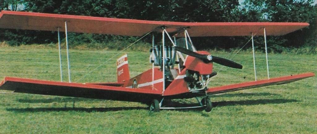
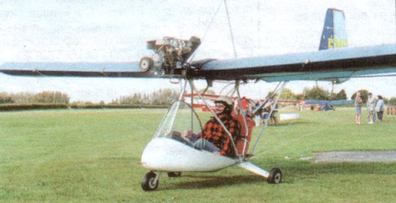
Single seat single engined biplane with con¬ventional three axis control. Wings have un¬swept leading and trailing edges, and constant chord; conventional tail. Pitch control by fully flying tail; yaw control by fully flying rudder; roll control by full span ailerons; control inputs through stick for pitch/roll and pedals for yaw. Wings braced by struts and dupli¬cated transverse X cables; wing profile; 100% double surface. Undercarriage has three wheels in tail dragger formation; coil spring suspension on tailwheel and axle flex suspension on main wheels. Push right go-¬right tailwheel steering connected to yaw control. No brakes. Composite fuselage, partially enclosed. Engine mounted between wings driving tractor propeller. Patented composite wing structure using waterproof fabric covering with heat set backing adhe¬sive. Rigging wires of stainless steel. Airframe uses aluminium alloy seamless drawn tube and cadmium plated aircraft quality nuts and bolts.
The Super Tiger Cub 440 is the logical development of the Micro Bipe prototype, with the open framework replaced by a partially enclosed cockpit and the 250 engine discarded in favour of a 440. Wing span is increased to keep the wing loading of this heavier aircraft within the UK microlight definition. Although a nosewheel was retained for test work on the pre production prototype of the Super Tiger Cub 440, it is not fitted on production machines. Particularly noteworthy is the ease of rigging. Simply by removing three locking pins per side, the Super Tiger Cub 440 is made ready for trailer transport.
The aircraft is offered in three forms: part kits, full kits or ready to fly. Part kits are numbered one to eight and can be purchased one at a time as the builder’s finance permits, a system which also permits the manufacturer to keep costs down by producing each part kit in quantity. By 1982 over 150 of these aircraft were in the process of being built.
Engine: Robin EC44 50hp at 7000rpm
Propeller diameter and pitch 54 x 33 inch, 1.37x 0.84 m
Toothed belt reduction, ratio 2.4/1
Max static thrust 220 lb, 100kg
Power per unit area 2.72 hp/sq.ft, 29.7 hp/sq.m
Fuel capacity 6.0 US gal, 5.0 Imp gal, 22.7 litre
Length overall 13.3 ft, 4.05 m
Height overall 5.5 ft, 1.68m
Wing span 21.0ft, 6.40m
Constant chord 3.0 ft, 0.91 m (bottom wing), 3.5 ft, 1.07 m (top wing)
Dihedral 5 deg (bottom wing), 0 deg (top wing)
Sweepback 0 deg
Tailplane span 7.0ft, 2.13m
Rudder height 2.9ft, 0.88 m
Total wing area 136 sq.ft, 12.6 sq.m
Total aileron area 13.8 sq.ft, 1.28 sq.m
Rudder area 6.3 sq.ft, 0.59 sq.m
Total elevator area 14.6 sq.ft, 1.36 sq.m
Wing aspect ratio 6.4/1
Wheel track 4.2 ft, 1. 28 m
Tailwheel dia¬meter overall 4 inch, 10cm
Main wheels diameter overall 13 inch, 33cm
Empty weight 265 lb, 120kg
Max take off weight 500 lb, 227 kg
Payload 235 lb, 107 kg
Max wing loading 3.68 lb/sq.ft, 18.0 kg/m
Max power loading 10.0 lb/hp, 4.5kg/hp
Load factors +6.0, 4.0 design; +9.0, 7.0 ulti¬mate
Max level speed 80 mph, 129 kph
Never exceed speed 85 mph, 137 kph
Max cruising speed 70 mph, 113 kph
Economic cruising speed 60 mph, 97 kph
Stalling speed 30 mph, 48 kph
Max climb rate at sea level 900 ft/min, 4.6 m/s
Min sink rate 500 ft/min at 36 mph, 2.5 m/s at 58 kph
Best glide ratio with power off 7/1 at 35 mph, 56 kph
Take off distance 60 ft, 20 m on short grass
Landing distance 80 ft, 25 m on short grass
Service ceiling 10,000 ft, 3050 m
Range at average cruising speed 115 mile, 185 km
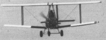
Single seat single engined biplane with con¬ventional three axis control. Wings have un¬swept leading and trailing edges, and constant chord; conventional tail. Pitch control by fully flying tail; yaw control by fully flying rudder; roll control by two thirds span ailerons on lower wing; control inputs through stick for pitch/roll and pedals for yaw. Wings braced by struts and cables; wing profile; 100% double surface. Undercarriage has three wheels in tail dragger formation with additional nosewheel; coil spring suspension on tailwheel, no suspension on nosewheel, and axle flex suspension on main wheels. Push-right go right tailwheel steering connected to yaw control; castoring nosewheel. No brakes. Aluminium tube framework, without pod. Engine mounted between wings driving trac¬tor propeller. Patented composite wing struc¬ture using waterproof fabric covering with heat set backing adhesive.
First shown late in 1981, the Tom Wright designed Micro Biplane, or Micro Bipe as it quickly became known, created enormous interest after looping at the Long Marston fly in in May 1982.
Although it was offered to the public as early as March 1982, the manufacturers were at that time in no position to satisfy the enormous interest that the tiny plane evoked and in May, many frustrated would be cus¬tomers later, the decision was taken not to go into production with the Micro Bipe as it stood, but to refine it, ‘productionise’ it, and set up a company to make and market it. The aircraft developed into the Super Tiger Cub 440.
Engine: Robin EC25PS 350cc
Length overall 13.0 ft, 3.96 m
Height overall 5.0 ft, 1.53m
Wing span 18.0ft, 5.48m
Constant chord 3.0 ft, 0.91 m
Sweepback 0 degs
Total wing area 108 sq.ft, 10.0 sq.m
Wing aspect ratio 6.0/1
Empty weight 165 lb, 75 kg
Max take off weight 375 lb, 170kg
Payload 210 lb, 95 kg
Max wing loading 3.47 lb/sq.ft, 17.0 kg/sq.m
Load factors; >+6.0, > 4.0 ultimate (with wing relief allowance)
Never exceed speed 75 mph, 121 kph
Max cruising speed 55 mph, 88 kph
Stalling speed 30 mph, 48 kph
Max climb rate at sea level 350ft/min, 1.8m/s
Take off distance 150ft, 45m on tarmac
1982: Herveport Ltd t/a Micro Biplane Aviation, Sopwith Works, Central Avenue Workshop, Nottinghamshire, S80 lEN, United King¬dom.
Built the Micro-bipe UL
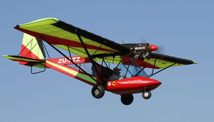
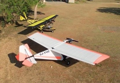
The Bat Hawk is a South African “Light Sport Aircraft” designed and built for African conditions. The Bat Hawk is a high wing monoplane with the crew of two seated side by side in an under slung tubular framed structure surrounded by a glass fibre composite fairing.
It features a strut braced high wing, a two-seats in side-by-side configuration open cockpit, fixed tricycle landing gear and a single Rotax engine in tractor configuration.
A conventional 3-axis light sport aircraft, the Bat Hawk has twin seats positioned side-by-side for full dual control and both crew members are protected from the weather by an aerodynamic fibreglass pod and large wrap-around windshield.
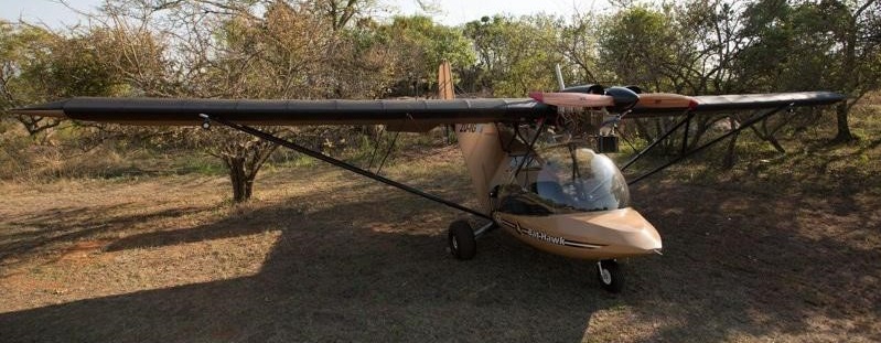
The propeller and the engine are mounted in a tractor position above and ahead of the crew. The empennage is conventional in location and layout. The undercarriage is a tricycle arrangement with a steerable nose-wheel. The wing, which is strut and lift wire braced, has two tubes forming the spars, one at the leading edge and one at the rear edge of the wing. All the above parts are manufactured from corrosion resistant aluminium alloy and stainless steel wires, whilst the air-frame and wings are covered with tensional Dacron sailcloth.
The Bat Hawk’s cockpit is very similar to that of a helicopter with excellent forward visibility as well as to both sides.

Attached to the rear spar are full span flaperons of similar construction and covering. They work independently as ailerons and together as flaps. There is no flap position indicator but approximate settings can be determined from the flap selector angle. Maximum flap movement is restricted by a limit stop mounted on the flap lever quadrant.
The fin, rudder, tail plane and the elevator are also of similar materials and construction. Tubes form the leading and trailing edges with the section being flat sided between. The rudder is actuated by cables running from the pedals. A control stop for the pedals is fitted at the front of the fuselage tube. The ailerons are controlled by cables from a torque tube connected to the central control stick, which has a built-in control stop. The elevator is actuated by a push/pull cable attached directly to the control stick which has built-in stops.
The main wide track undercarriage has the wheels supported by an inverted ‘V’ shaped glass fibre channel which, due to the material used, also acts as an effective spring. The nose wheel is held by two hydraulic shock absorbers, fixed directly to the top plate through a bearing which in turn is attached to the main fuselage cross tube. The shock absorber system allows the Bat Hawk to operate on rough terrain. The tried and tested Black Max Disc brake system is fitted to simultaneously actuate these brakes my means of a hand lever on the control stick. Differential braking is not provided and directional control on the ground is achieved by nose wheel steering. A MGL EMS is installed as standard equipment and enables one to monitor all 2 CHT’s and 4 EGT’s, voltage, oil pressure, oil temperature and RPM simultaneously.
The aircraft is supplied as a complete ready to fly and complies with the ASTM2245-12c Build Standard rules and regulations as well as South African Civil Aviation Type Approval.
Engine: Rotax, 100 H.P.
Wingspan: 9,50m
Length: 18.19 feet (5.544m)
Height: 3,20m
Empty weight: 573.2 lbs (260 kg)
MTOW: 1204.2 lbs (540 kg)
Maximum fuel: 123.0 lbs (56 kg)
Minimum solo crew weight: 163 lbs (74 kg)
Useful Load: 280 kg
Average dual crew weight 396.8 lbs (180 kg)
Take-off weight with full fuel/average crew 1100.0lb (499 kg)
Cruise Speed: 77 knots
Vne: 92 knots
Stall Speed: 36 knots
Take-off Run: 30-50m
Landing length: 50-60m
Undercarriage wheel track: 5.42 feet (1.652m)
Main wheel size: 8.00 x 6.ins
Nose wheel size: 4.00 x 4.ins

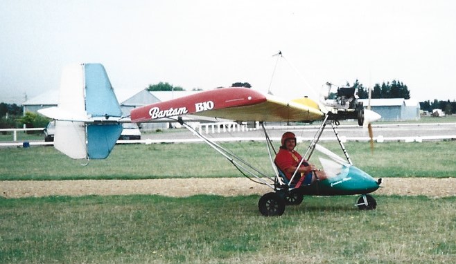
Continuing development and improvements to the B10 design resulted in the B20 model. Requests kept flooding in to the factory for a two-seater version and it was not long before the B22 came on the scene. Sporting dual seats and controls. In 1985 the Micro Aviation NZ Ltd, B22 Bantam, made its successful maiden flight from the company’s Te Kowhai base – a two-place microlight. At the hands of Max Clear, co-founder of the company, the aircraft began a series of proving flights. The B22 model is aimed at the flight training market.
Basically a stretched version of the popular B20, the side-by-side two-seater incorporates a number of new design features including lift struts which replace the two outer flying wires to each wing. However whilst the two inner flying wires have been retained, gone is the familiar kingpost and associated landing wires. A redesigned empennage now means that fin and stabilizer are interchangable, reducing complexity and keeping construction cost down. These refinements were to be incorporated into all future production B20 models as well.
A redesigned wing, incorporating a higher lift aerofoil section, utilises similar construction techniques as the single seat Bantam but an increased span – now 32 feet – gives the B22 162 square feet of wing area – an increase of more than 10 percent. Full span flaperons have been retained. Power is supplied by the Austrian Rotax 503 with an integral gearbox driving a locally manufactured 62″ x 36” Perry prop. Fuel is contained in a 29 litre cylindrical aluminium tank (sufficient fuel for more than 2.5 hours of flying) designed and manufactured by John Smith, the other partner in this venture. Situated directly behind the seats, the tank has an external site gauge easily visible in flight. A wide fibreglass pod and windshield, designed by Micro Aviation and built by Ultralight Aircraft Manufacturing at Ardmore, provides protection while permitting excellent visibility.
Six B-22 Bantams were built, the first flying on 15 January 1986, and – after the paperwork had exceeded the weight of the B-22 Bantam and test pilots had flown a trouble free 150 hours – the type certificate came to hand.
Further impetus to the project was added by the constant stream of visitors to the Te Kowhai hangar, more than a few matching enthusiasm with orders. With a more powerful Rotax 582 engine, it became the standard production model in 1986. Twenty B-22s were completed during 1986; the 50th Bantam being completed shortly after Christmas 1986.
An agricultural spraying version was designated the B22AG.
When the Jabiru engine was first fitted to the B22 it was called the B22J Bantaroo, though this label was soon dropped. The B22J increased gross weight from 377kg to 430kg.

Not that development stopped here either, although all of the models were Type approved in New Zealand, it was found that in order to gain both International recognition and approval to use the aircraft as a trainer, called for the production of a fully Certified version.

As a result the factory geared itself up for this mammoth task. The wing was re-designed with a wider chord, shorter span and Clark-Y airfoil section, plus two more ribs. Changes were also made to the tail section, flaperons and cockpit, to name a few. The New Zealand Department of Civil Aviation supervised, tested and advised throughout this long drawn out process, finally awarding the new B22S full certification status in 1995.
Refinements made the vertical stabiliser and rudder interchangeable with the horizontal stabiliser and more eyebolts in the aileron and rudder and new instrument panel. With the introduction of the B22S in 1994, the serial sequence changed to year then number, at 94-001. The S suffix related to the British CAR regulation section S, including a fuel cock and a shortened fuel tank.
The Bantam B22S and B22J (with the new Jabiru 4-stroke engine) models are marketed in a number in a number of countries with in excess of 240 units having been produced. A paraplegic version with modified flght controls was also available.

Under development in 2009 was the B22UL powered by a ULPower UL260i engine with Full Authority Digital Engine Control, producing 71kW (95hp).
Stall: 23 kt / 26 mph / 43 kmh
Cruise: 56 kt / 64 mph / 104 kmh
VNE: 80 kt / 92 mph / 148 kmh
Empty Weight: 176 kg / 388 lbs
MTOW Weight: 430 kg / 948 lbs
Glide Ratio: 7:1
Take-off distance (50ft obstacle): 100 ft / 30 m
Landing distance (50ft obstacle): 100 ft / 30 m
Engine: Rotax 503, 48 hp.
Wing span: 9.8m
Length: 5.5m
Empty wt: 144kg
MAUW: 356 kg
Max cruise: 104 kph
Range: 260km
Engine: Rotax 532, 64 hp.
Engine: Rotax 582, 63 hp
Wing span: 9.03 m
Wing area: 15.1 sq.m
MAUW: 378 kg
Empty weight: 176 kg
Fuel capacity: 40 lt
Max speed: 113 kph
Cruise speed: 105 kph
Minimum speed: 42 kph
Climb rate: 3.4 m/s
Certification: BCAR S
Seats: 2
Price (1998): £18,794
B22J
Engine: 4 cylinder Jabiru 2.2 lt.
Gross weight: 430kg
B22S
Engine: Rotax 582
B22UL
Engine: ULPower UL260i, 95 hp.
The B-10, too heavy for Class 1 microlight operation, was refined into the lighter B-20 with a new wing and tailplane section, less drag and a lighter engine. Refinements to the B10 design included pull-on sailcloth and fabricated ribs, resulting in the B20 designation. Appearing much trimmer and performing as well, if not better, than the heavier and more elaborate B-10 Bantam. First flown on 23 December, the B-20 was designed specifically to a lower empty weight in order to meet the microlight philosophy of a very basic flying machine. The result was a Bantam with somewhat better performance than the B-10 and the only penalty being a smaller fuel tank with consequently less endurance. The geared Rotax fitted to the B-20 is much quieter than the belt driven version fitted to the B-10, one B-10 owner has already made the conversion to a geared engine.
Designed by the Max Clear and John Smith design team at Te Kowhai, the B-20 has replaced the B-10 on the production line. The first production B-20 (s/n 0015) was delivered south by pilot Otto Gram to the South Island’s West Coast in early February. After a production run of 17 were built during 1985, the B-20 itself was superseded by the B-22. Two were exported to Australia. There were minor differences, the most significant being the “flaperons” which enhanced an already excellent take-off performance with a reduced approach speed. Conventional 3-axis controls.
Whereas the B 10 was an individually constructed (or at least individually finished) aircraft, the B 20 was the built as the start of the assembly line at Micro Aviation at Te Kowhai.
The B 20 had the same basic airframe as the B 10 but with a differently shaped pod and without the drooped wingtips. It had a tapered wing and a different airfoil to the B 10. It also had pre-sewn covers for the flying surfaces (whereas the B 10 had ceconite fabric glued to the airframe). Original examples had a Rotax 447 engine. 15 Bantam B 20s were made at Te Kowhai before production geared up with Micro Aviation producing the two seat Bantam B 22.
Engine: Rotax 447, 40 hp.
Wing span: 8.69m.
Length: 5.15m.
Empty wt: 114 kg.
MAUW: 250 kg.
Max cruise: 93 kph.
Range: 170 km.
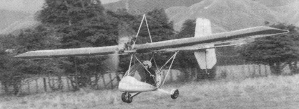
The MICRO Aviation (NZ) B-10 Bantam became the first New Zealand designed microlight to receive full CAD type approval following successful flight trials at Te Kowhai. Production facilities at Te Kowhai were set up in 1984 to manufacture the first ten Bantams (all pre-sold) and since the type approval further Bantams have been built.
Designed by John Smith and Max Clear, and based on the Phantom ultralight, the B-10 first flew, piloted by Keith Trillo, on 16 November 1983. A further 12 B-10 Bantams followed, more or less identical apart from paint schemes and fin and rudder configuration. All performed well – so well in fact that the owner of the last B-10 built borrowed the plans and another two came into being in the Cambridge district at the hands of the Williams brothers.
The B-10, too heavy for Class 1 microlight operation, was refined into the lighter B-20 with a new wing and tailplane section, less drag and a lighter engine. Production ended when superseded by the B-20 Bantam. Conventional 3-axis controls.
Engine: Rotax 503, 50 hp.
Wing span: 28 ft 6 in (8.69m).
Wing Area: 146.459sq.ft.
Length: 17 ft (5.15m).
Empty wt: 127 kg.
MAUW: 250 kg.
Maximum Design Load Factors: +9G, -6G.
Maximum Level Speed: 54 knots
Maximum Cruising Speed: 50 knots
Economical Cruise: 40 knots
Stalling Speed: 21 knots
Vne: 70 knots
Maximum Rate Of Climb: 550fpm
Range: 200 nautical miles.
