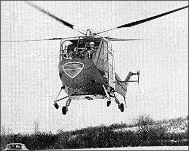
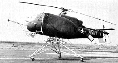
After the LZ-2A Pelican, Doman’s system was designed into a larger helicopter that was seen as a viable commercial production machine. The LZ-4A had a large fuselage with three rows of double seats in the main cabin and a two-crew flight deck in front. Large folding doors provided access for loading bulky cargo into the main compartment. The tail boom was conventional with a cranked-up rear section mounting a tail rotor, and the LZ-4A sat on a four-leg undercarriage with trailing link dampers. A 400hp Lycoming SO-590-B engine was positioned in the lower nose, driving the four-blade rotor via a flexible transmission. Following its first flight in November 1950, and subsequent testing, Doman moved on to the improved LZ-5 and transferred the LZ-4A (N74147) to Curtiss Wright, where it was given the designation of CW-40, as a test vehicle. The LZ-4’s first flew in November 1950.
LZ-4 Number of seats: 8 Engine: 1 x Lycoming SO-590-B, 400hp Rotor diameter: 14.64m Length: 11.7m Height: 3.41m Gross weight: 2165kg Empty weight: 1343kg Cruising speed: 125km/h Rate of climb: 244m/min Absolute ceiling: 4880m Range: 336km
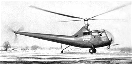
Doman Helicopters Inc. was founded in 1945 for the purpose of exploiting patents taken out by Gliden S. Doman, who during World War II had worked with Sikorsky. The patents related to a new system for controlling and attaching helicopter blades. These included a new hub system which was essentially similar to the mechanism used on a variable pitch propeller. The rotor system also incorporated a gimbal mounting to provide the necessary tilting of the rotor disc and rotating it by means of a unique constant-velocity driving system. No blade-flapping hinges, drag hinges or hinge dampers were required and bearings subject to centrifugal loads with oscillating motion are reduced to a minimum. The Doman rotor incorporates the speed reduction gearing as an integral part of the rotor assembly. All moving parts are contained within a common housing which precludes damage from weather or foreign matter. Doman’s theories were tested initially by installing an experimental system on a USAF Sikorsky R-6 in 1947. The rotor had four blades, and though their length was increased from 11.58 to 12.2 metres, this resulted in improved hovering ability and did not lower the top speed. The helicopter was known as the Doman LZ-1A and it started flight tests in early 1950 with good results. The first flights took place early in 1950 and it should be noted that during one experimental flight this rotorcraft flew for forty minutes without the pilot needing even once to touch the cyclic pitch control. It was followed by the larger LZ-2A Pelican.
LZ-1A Engine: 1 x Franklin 0-405-9, 245hp Rotor diameter: 12.2m Length: 10.34m Height: 3.35m Gross weight: 1350kg Empty weight: 871kg Cruising speed: 136km/h Rate of climb: 275m/min Range: 640km Number of seats: 2
Glidden J. Doman Doman-Frasier Helicopters Inc Berlin-Doman Helicopters
Founded in 1945 by Glidden J. Doman at Danbury, New York, to construct rotorcraft with hingeless rotorblades and totally enclosed self-lubricating hub. Produced LZ-1 a, LZ- 2a Pelican, LZ-4, LZ-5 ,and a developed version, DB-1 OB, in 1953. At one time known as Doman-Frasier Helicopters Inc. Doman H-31 of 1952 was license-built by Hiller Aircraft Company Inc. Operations transferred to Puerto Rico, with continued production of DB-10B and name changed in 1967 to Berlin-Doman Helicopters, recognizing interests of Chairman Dr. Don R. Berlin.
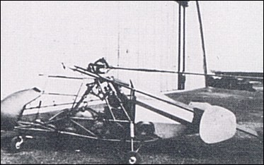
The WNF-342 was the work of three engineers – Friedrich von Doblhoff, A.Stepan and Theodor Laufer – at the Wiener Neustadter Flugzeugwerke in Vienna. The operating principle was to use a conventional piston engine driving a compressor to provide a compressed air supply, which, after mixing with fuel, was fed as a combustible mixture up through the rotor hub and out through the three hollow rotor blades to be burnt in tip-mounted combustion chambers, thereby generating thrust.
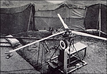
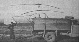
Doblhoff first built, in 1942, a ground test rig to prove the principle of his proposed rotor drive system, consisting basically of a trio of hollow rotor blades mounted on a scaffold with the fuel/air mixture fed through each blade to a small jet unit at the tip. A compressed air tube entered the rotor hub, and vaporized petrol was added by special tubing. The mixture was ignited at the blade tip by an automobile sparking plug. The demonstration proved so successful that the rotor actually ‘took off’ from its moorings, lifting about a yard into the air an anvil that had been attached to it to hold it down. Encouraged by this success, Doblhoff and his team then applied the principle in the small single-seat WNF-342V1 which he hoped would meet a German Navy requirement for an observation helicopter to be carried by submarines or small naval vessels.
This first prototype, powered by a 60hp Walter Mikron II engine, was flown in spring 1943. The airframe, constructed from welded steel tube and fabric covered, had a gross weight of 360kg, twin tail fins and a tricycle undercarriage. The rotor was fitted with flapping and drag hinges.
WNF-342 V1
Flight testing revealed the need for rather more side area, but performance was otherwise satisfactory, and when the WNF factory was superficially damaged during an Allied air attack in mid-August 1943 the aircraft was moved to a safer site west of Vienna, at Obergraffendorf. Here a second machine, the WNF-342 V2, was built, being a somewhat heavier aircraft at 460kg gross weight, despite its open-framework fuselage. The main difference lay in the sail-like tail unit, this comprising a large single rectangular fin and an elongated rudder pivoting about a horizontal axis. The 60hp Walter Mikron engine was replaced by a 90hp Walter Mikron engine.
WNF-342 V2
A conventional piston engine drove a compressor, in this particular case the supercharger blower of an Argus 411 engine. The mass flow of compressed air produced by this blower was mixed with fuel before passing through the hollow rotor blades to chrome steel combustion chambers situated at the blade tips. Combustion of this fuel-air mixture occurred at a rate of approximately 280 times per second.
Doblhoff WNF-342 V2
Starting with the V3 machine, increases were made in rotor diameter, and both the V3 and V4 used the extra power of the 140hp BMW Bramo Sh 14A engine to drive the compressor. In all designs, an Argus As 411 supercharger was adapted as a compressor. Before the end of the war, consideration was being given to replacing the compressor system with rotor mounted pulse-jets or even miniature turbo-jets. Within their limited performance, the V1 and V2 machines flew smoothly enough, but serious vibration manifested itself in the V3 machine and ground resonance vibration eventually destroyed it.
WNF-342 V2
Each of the first three machines (V1, V2, and V3) was provided with only a small rear propeller to blow air at the tail surfaces for steering. For the first three machines, although flapping and dragging rotor hinges were provided, no blade pitch-change arrangement was made since this was not required for early tests, vertical control being provided simply by varying the rotor speed.
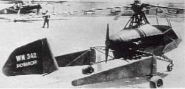
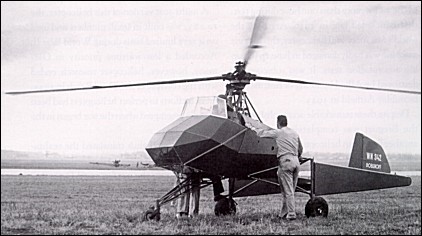
Experience with the first two machines showed that the high fuel consumption of the tip-jets would make the WNF-342’s operating costs prohibitive, and so a major design change was introduced in the V3 and V4 prototypes. The tip-drive system was retained for take-off, hovering and landing only, a selective clutch enabling the engine (now a 140hp Siemens-Halske Sh.14A radial) to drive a conventional pusher propeller for forward flight while the rotor blades ‘free-wheeled’ in autorotative pitch. To clear this propeller the rotor pylon was raised above the cabin and the tail unit was redesigned as a twin-boom assembly, that of the V3 carrying two end-plate oval fins and rudders while that of the V4 had a single fin and rudder mounted on the tailplane centre. Gross weight of the V3, a single-seater with 9.88m diameter rotors, was 548kg.
By the time the WNF 342 V4 was built a control method had been devised to provide both collective and cyclic pitch control. Each rotor blade was connected to the rotor head by means of a flexibly coupled tube flanked by steel-strip leaf-type spring straps connected to an upper aluminium alloy casting. This upper casting rotated in a lower fixed casting, a seal being provided between the two, and fuel mixture flowed into this hollow assembly to be piped out to each blade. Passing up through the casting was a hollow fixed shaft which carried a bearing for the upper casting and which was flexibly connected to the helicopter framework. Inside this hollow shaft, a solid shaft rotated in a spherically seated bearing to carry the blade pitch control spider at its head. Thus, angular displacement of this solid shaft tilted the spider to give appropriate cyclic pitch control. For collective pitch control, the spider was connected to the solid shaft by means of a pressure regulator connected to the upper casting (containing the pressurized fuel mixture) by a pipeline. The spider was given a vertical movement according to the mixture pressure opposed by springs within the regulator. In addition, collective pitch was governed by the torsional stiffness of the centrifugally-loaded spring straps. When the pilot moved the throttle control, a rapid increase (for example) of mixture pressure and jet thrust followed by an increase in collective pitch ensued, while the rotor rpm remained constant.
WNF-342 V4
The V4 had a second propeller mounted co-axially to provide thrust for forward flight when clutched to the compressor motor. Thus, by gradual development, the rotor jets (which had a high fuel consumption) were only used for take-off, hovering and landing, and the rotor blades turned by autorotation for forward flight in the manner of an autogyro. The V4 had side-by-side open cockpits for a crew of two.
The V4 was hovered for a total of 25 hours, it was not tested in forward flight above 40 to 48km/h before the programme had to be halted. In April 1945, Soviet troops approaching Vienna caused Doblhoff’s team to withdraw hastily to Zell am See where the V2 and V4 machines were captured by United States’ forces. Doblhoff later accompanying it back to the United States to assist with further tests before joining McDonnell to work on development of the XV-1. Stepan, who had done most of the test flying on the WNF-342, joined Fairey in the United Kingdom after the war, while Laufer went to work for the SNCA du Sud-Ouest in France where he worked on the jet-propelled Djinn.
On September 9, 1946, the General Electric Company (specifically, the Thermal Power Systems Division of its General Engineering and Consulting Laboratory) was permitted by the USAAF to evaluate the WNF 342 V4 in connection with that company’s work on the power plant of the XR-17 helicopter, which would later become the Hughes XH-17. It was shipped by a Fairchild C-82 to Schenectady, New York on December 6, 1946, where it was tested and studied by General Electric under Army Air Force Contract No. W-33-038-AC-16283. This article presents their evaluation report dating from April 30, 1948.
Igor Bensen, one of the primary authors of the report, would go on to perform many test flights of the WNF 342. Unfortunately, he suffered severe spinal injuries when the helicopter was destroyed in a ground resonance accident; these injuries would plague him throughout his life. However, they did not stop him from playing a significant role in the development of the Hughes XH-17 and eventually founding his own company, Bensen Aircraft, which produced a successful line of gyrogliders and autogyros over the course of several decades. Doblhoff was also involved with the XH-17 program, as well as the McDonnell XV-1 convertiplane, among others.
The WNF 342 V4 has been preserved by the Smithsonian Institution, Washington.
Friedrich Doblhoff began work on a jet helicopter in 1942, with a piston engine delivering ram air via a compressor to tip orifices. Development was taken up by Wiener- Neusatdter Flugzeugwerke and resulted in four models of the WNF 342.
Jess Dixon, of Andalusia, Alabama, got tired of being tied up in traffic jams, so he designed and built this novel flying vehicle around 1940. It was a combination of automobile, helicopter, autogiro, and motorcycle. It had two large lifting rotos in a single head, revolving in opposite directions. It was powered by an air-cooled 40 h.p. motor. He claimed his machine was capable of speeds up to 100 miles an hour, according to Modern Mechanics (Nov, 1941).
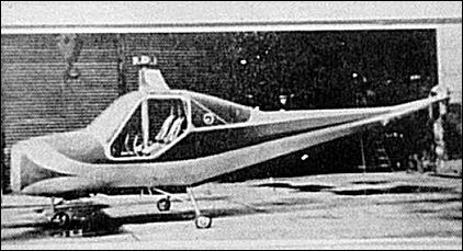
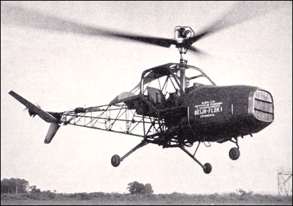
The Beija-Flor is a two-seat helicopter, which was designed in 1956 and built to the initial design of Professor Heinrich Focke at the Centre Tecnico de Aeronautica at the military research and overhaul centre at Sao Jose dos Campos. The forward-located 225hp Continental E225 engine drives the main and tail rotors through a centrifugal clutch and a David Brown lorry worm and wheel. The main rotor incorporates a mechanical-hydraulic automatic stabilising mechanism which reduces flapping to zero in the pitch direction. Roll control is provided by normal “swash-plate” movement. Pitch and yaw control is provided by the unique V-type intermeshing twin tail rotor which also serves to incline the main rotor plane for forward flight. An open structure tubular steel tail boom carried a pair of tail surfaces and a small tail rotor. The material used in the construction of the helicopter is almost entirely of national origin and this has unavoidably led to an excessive weight.
The Beija-Flor is the first helicopter to be designed, built and flown in Brazil and was first flown on 1 January 1959 by Colonel Aldo Vieira da Rosa, a Brazilian Air Force officer and director of the Instituto de Pesquisas e Desenvolvimento da Aeronautica. The first flights concentrated on a preliminary assessment of control and stability. It was damaged in an accident and it is thought that further work on the Beija Flor was then abandoned.
Beija-Flor BF-1 Main rotor diameter: 9.0m Overall length: 8.43m Height over rotor hub: 3.15m Weight loaded: 950kg Max speed at sea level: 150km/h Cruise speed for max range: 130km/h Cruise speed (75% power): 140km/h Max rate of climb: 370m/min Service ceiling: 3500m Max ceiling: 3750m Hover ceiling with ground effect: 2700m Hover ceiling without ground effect: 1400m Range at best cruise speed: 270km Max endurance: 3h
Brazil The aircraft department of the Instituto de Pesquisas e Desenvolvimento (IPD). From 1970 concentrated entirely on research, all design and development being handed over to Embraer. Between 1959 and 1964 it developed prototypes of the Beija-Flor two-seat light helicopter, designed especially for Brazilian conditions by Prof. Heinrich Focke, formerly of Focke-Achgelis.
The Del Mar DH-2C Whirlymite was an American radio-controlled target drone helicopter first flown in 1963 after design started in 1960. The Del Mar DH-2C was a minimum-size, low-cost, destructible target developed from the Del Mar DH-2 Whirlymite helicopter and fitted with a 7/16th scale replica of the Bell 205 helicopter fuselage fitted with a counter to record hits whenever pierced by a projectile.