Fairey Rotodyne

With the concept of the convertible helicopter proved on a small scale with the Jet Gyrodyne, the proposal put forward by Dr. J.A.J. Bennett and Captain A.G. Forsyth in 1947 for a large compound helicopter looked viable, and various designs were considered.
The first mention of the project and of the name Rotodyne was made in March 1951 by the Ministry of Civil Aviation’s Interdepartmental Helicopter Committee in its initial report. No details were given, but it was reported to have two propeller-turbines and tip-jets, to have a cruising speed of 217km/h and capacity for 23 passengers. This was probably the Mamba-engined project.

Confirmation of the need for such an aircraft was provided by the British European Airways specification of December 1951 for a short/medium-haul ‘BEAline Bus’. Five manufacturers submitted projects to meet this earlier specification for a 30/40-passenger aircraft. Fairey’s original proposal again incorporated the projected D.H. powerplants. These were in two underwing nacelles, in each of which was located a main gas-turbine driving an auxiliary compressor and, mounted in tandem, a second turbine driving a constant-speed propeller through a reduction gear. Air for this turbine was tapped from the auxiliary compressor of the main engine. The rotor was four-bladed, with pressure-jet units at the tips.

The Gyrodyne had rear clam-shell doors allowing the loading of large motor vehicles. A forward-located door permitted simultaneous entry and exit of passengers. The passenger compartment was 14m long, 2.4m wide, and 1.8m in height. The tail lower tail surfaces were oriented straight down, while the upper surfaces were canted at about a 45 degree angle.
The final version, with two Elands driving propellers and/or auxiliary compressors, was outlined in 1953 and formed the subject of a Ministry of Supply research contract. This became the definitive prototype, leading later, without very fundamental changes, to the proposed production Rotodyne FA-1, or Type Z, of 1959-60, with planned seating for up to 70 passengers. For this, XH249 (F.9430), the Elands could not provide the power required, so two 5,250shp Rolls-Royce Tyne propeller-turbines were envisaged. But in hot/high conditions, even this power would have been only just adequate in the engine-failure on take-off case, and Rolls-Royce suggested separate air-producing engines to supply the tip-jets.

Fairey Rotodyne – Eland engines

The proposed solution was to install, at the rear of each nacelle, an RB.176 in which a lightweight gas-turbine drove an auxiliary compressor. By this use of separate propulsion and lift power there would be a considerable increase in weight, but the arrangement gave worthwhile gains in off-design conditions. The Fairey pressure-jet unit for the prototype consisted of a circular-section flame-tube fed by three air pipes and one fuel pipe. This was faired within a streamlined nacelle and terminated in a simple propulsive nozzle.
The BEA type specification for the production Rotodyne stipulated an initial climb, at zero forward speed and maximum weight, of not less than 1823m/min, and a noise level, at a distance of 183m, of not more than 96 decibels. With the power planned for the production Rotodyne the noise level for the existing tip-jets would have been about 113 db. To achieve the necessary 17-db reduction in noise level a complete redesign of the pressure-jet was planned. This would have been in two-dimensional form, occupying the last 1.2 metres of each blade, with nine circular flame-tubes in a combustion chamber submerged within the blade profile. Much work was done on silencers, but it was never reduced to the 96 decibels that the authorities demanded.

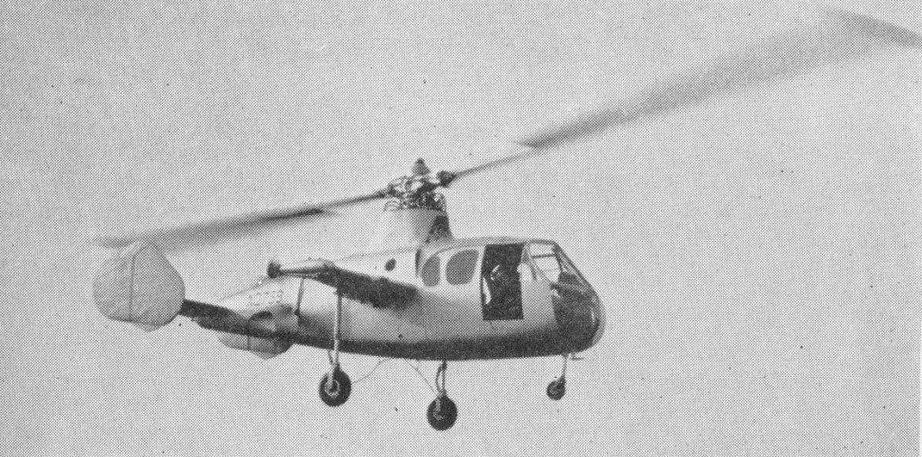
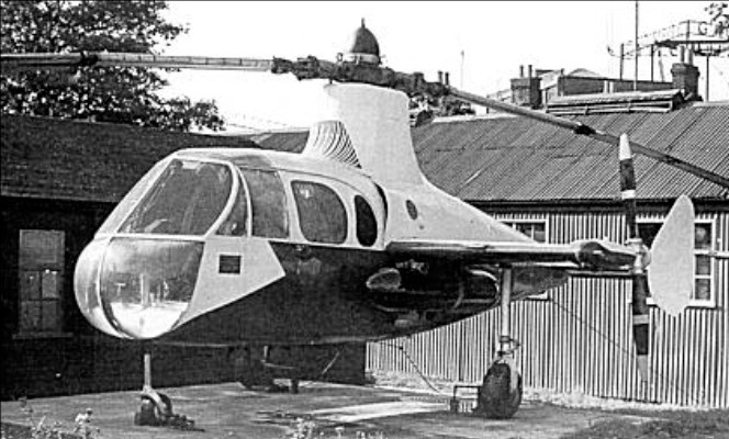
New test facilities were set up at White Waltham in 1951 for the development of the tip-jets. These consisted initially of a test stand and a rotating rig for chamber-spinning tests. A Rolls-Royce Dart engine, with air tapped from the combustion chambers, was used as a compressor plant for the rig; two other Dart compressor plants were used for the air supply to the rotating stand. On this, a balanced single-bladed rotor, with hingeless hub, was used to investigate tip-jet light-up, regulation, performance, cooling and loads during rotation. Prior to installation on the Jet Gyrodyne, a complete rotor, including hub, blades, jet units and controls, was installed. By the end of 1953 the chamber and rotor had been developed, and the Jet Gyrodyne flew untethered for the first time in January 1954.

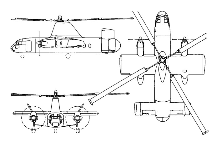
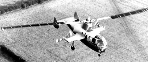
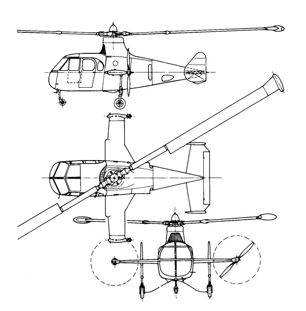
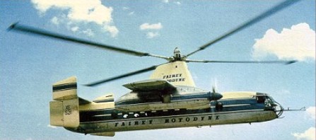
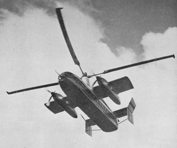
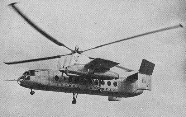
The Rotodyne was a square-section fuselage with untapered 14.17m stub wings on which were mounted two 3000shp Napier Eland turboprops for forward propulsion. The main wheels of the tricycle landing gear retracted forwards into the nacelles, and the nosewheel forwards below the cockpit. Twin fins and rudders, later joined by a central fin, were mounted on an untapered tailplane set on top of the rear fuselage. A large four-bladed rotor for vertical take-off and landing was driven by tip jets which received compressed air from the Eland engines via a compressor. To provide compressed air for the jets the two 2,800shp Napier Eland N.E1.7s operated as dual-purpose powerplants – acting either as normal propeller-turbines or as pressure-generators according to requirements. They were virtually normal Elands up to the rear of the turbine casing, where there was a nine-stage axial compressor driven by the power turbine through an hydraulic clutch. For take-off and landing most of the engine power was absorbed by the compressor, which delivered air to the internal duct system of the rotor. The small amount of remaining power of the engines went to the propellers for yaw control. In cruising flight all the power went to the propellers, with the rotor autorotating. Each engine fed air to two opposing blades so that, in the case of failure of one engine, there would be adequate pressure to keep two jets burning efficiently and giving maximum thrust.

All the earlier flying was completed with the fixed undercarriage while a revised form of retractable undercarriage, with special dampers, was designed and manufactured. This was fitted to the prototype soon after mid-year 1958 when the initial transition trials had been completed and the Rotodyne was being flown faster and for longer periods in the ‘winged autogyro’ mode.

Following the resonance and running tests, the first untethered flight of the Rotodyne, XE521 (F.9429), was made by W. R. Gellatly and J. G. P. Morton at White Waltham on 6 November, 1957, and two further flights, carrying a flight observer, were made on the first day. Originally it had been intended to keep within the ground cushion during the early flights, but the prototype was taken on a circuit of the aerodrome, well above cushion height, on one of the first three flights which were made at a weight close to the 15,000kg maximum.

Until 10 April, 1958, all flights were made in the helicopter mode. On that day, at 1220m, the first transitions were made to and from the autogyro mode and thereafter a stage-by-stage transition technique was further evolved to ensure complete safety at all moments during the manoeuvres. During the 70 earlier helicopter flights, speed had been built up to 250km/h and altitude to 2072m before transition tests were started.

In its original form the control system followed that of the Jet Gyrodyne, with direct roll and fore-and-aft control through the cyclic pitch-change of the rotor-blades; with a trimming ‘elevator’ used to select fuselage attitude (and consequently wing lift) in cruising flight; and with yaw control by differential propeller-pitch at low speeds or when hovering, and by rudders at higher cruise speeds. Early in the test programme it was found that the fore-and-aft attitude control, using the separate functions of cyclic rotor-control and elevator trim, produced some difficulties. The solution was to link the elevator to the longitudinal cyclic control for both slow and high-speed flight and to disconnect the cyclic control when cruising.

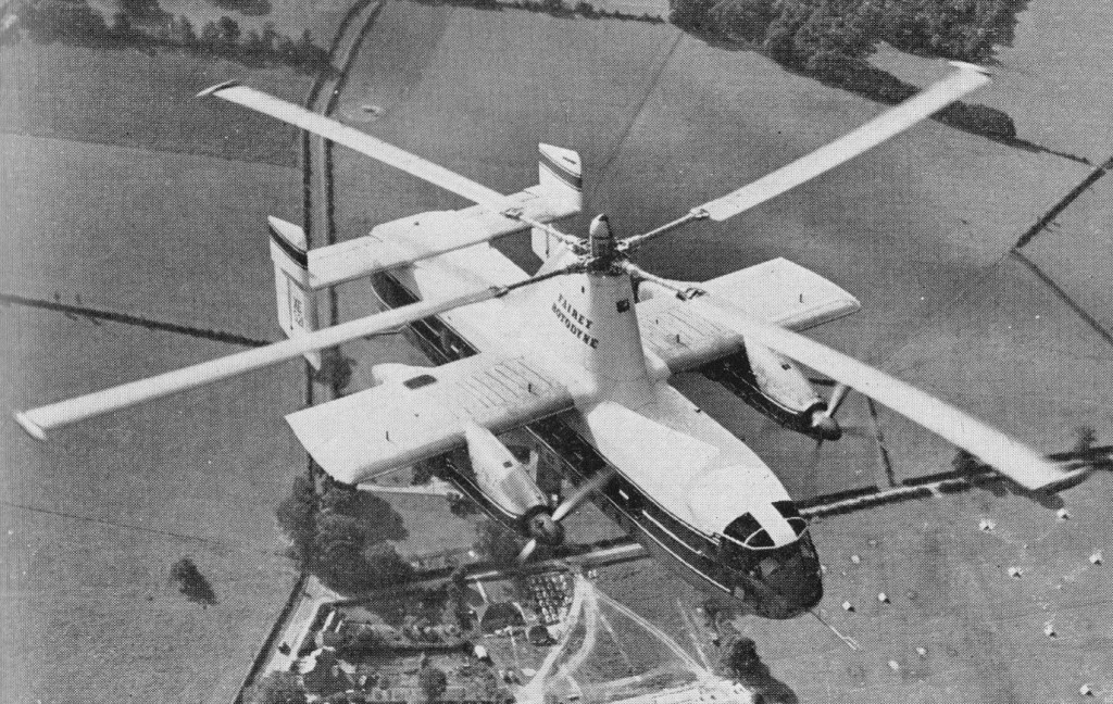
Later, when it was found that the economical cruising speed was more like 273km/h than the originally planned 209km/h, it was found that, at higher speeds, the wing was doing too much work and the rotor too little, so that the blades were flapping and the control margins were inadequate. The wing, originally set at an incidence of 4°, was re-set at 0° and fitted with ailerons, the operation of which was linked directly to the cyclic lateral control of the rotor. The outward-sloping upper fins were also moved to the vertical so as to reduce the rolling tendency with yaw. These changes produced a normal ‘aeroplane-type’ rolling control for the pilot, and the situation was further improved later by the fitting of a third upper fin.

Towards the end of 1958 a decision was made to establish a speed record with the Rotodyne. The 100km closed-circuit category was considered to be the most usefully representative of the kind of operation for which the Rotodyne was designed and that in the new convertiplane class (E.2) was chosen. On 5 January, 1959, the Rotodyne was flown by Gellatly and Morton, with Dr D. B. Leason, Fairey powerplant flight observer, and E. J. Blackburn, strain-gauge operator, as ‘passengers’, over a measured circuit between White Waltham and Hungerford, Berkshire. The flight was completed at an average speed of 307km/h – which was 79km/h higher than the equivalent record for a helicopter and nearly 48km/h higher than that for absolute speed in a straight line. At that time the Rotodyne had not yet been modified with the reduced wing-incidence and the fitting of ailerons to improve control at higher speeds. The record, which was confirmed in March, stood until October 1961, when it was beaten by the Russian twin-rotor Kamov Ka-22 Vintokryl convertiplane.

On 16 June, 1959, the Rotodyne was taken outside the United Kingdom for the first time when it was flown to Paris for the 23rd Aeronautical Salon from London’s Heathrow Airport, via the Allee Verte heliport at Brussels and the Issy heliport in Paris before landing at Le Bourget. After demonstrations there, and at Versailles for officers of the North Atlantic Treaty Organization, the Rotodyne was flown back to Heathrow.

During 1959 the wings were given ailerons and increased incidence, and the vertical tail surfaces were also revised. On 7 February 1960, XE521 resumed trials with an added central fin, shortened exhausts and a fully-faired rotor pylon.

Budgetary problems of the time saw the RAF and British Army withdraw their interest and the Rotodyne became a wholly civil project.

During 1958 the Kaman Aircraft Corporation secured a licensing agreement for sales and service in the USA with a possibility of manufacture there. Okanagan Helicopters of Vancouver was interested in three and Japan Air Lines was considering the type for domestic routes. However, the biggest potential customer was New York Airways, which joined with Kaman in a letter of intent for five, plus options on 10, for delivery in 1964.
The provisional order from NYA was for the bigger-capacity, 54/65-seat Rotodyne powered with Rolls-Royce Tyne propeller-turbines and with a gross weight of 22680kg. There had been earlier references to the use of Tynes in the production version, but this order led to the first fuller statements about this version, for the development of which an additional GBP8-10 million was needed. The Government had offered to contribute half this sum, up to a certain fixed maximum, with repayment through a sales levy, but this was conditional on a firm order from BEA. Confirmation of the NYA order depended on several factors — including one that the first ‘Mk.2’ Rotodyne should be flying on test by the autumn of 1961 and another that the noise-level should be acceptable to the airline and airport authorities.

At the Paris Salon in June 1959 a model of the production version had been exhibited in the markings of New York Airways.

Fairey needed up to GBP 10 million to develop this version and was offered 50% of this by the government if BEA would place a firm order. The government contribution was to be a loan, repayable by a sales levy. In 1960 Fairey merged with Westland and although initially the Rotodyne project looked secure, it was not. In April 1960 Okanagan cancelled its order because of the long delivery dates, and five months later New York Airways expressed concern over the delay in production plans. Westland was then involved in taking over Bristol’s helicopter programme as well as with other work in hand. This, together with the ever-increasing weight of the Rotodyne, which reached a stage where the Eland could no longer be developed and the Tyne could not be afforded, led to withdrawal of government support, and the project was cancelled on 26 February 1962. On that date the British Minister of Aviation, Mr Peter Thorneycroft, said that, because of the costs involved, it was necessary to ‘forego the operational advantages’ offered by the military version, and that British European Airways, then its only potential British civil operator, had regretfully concluded that ‘the commercial prospects on their routes were not sufficiently assured to justify the heavy liabilities involved’ in placing a production order. In the absence of any firm order, Westland Aircraft did not feel justified in proceeding with the project.
GBP11 million was spent during the nine years or so following the placing of the original research contract in July 1953. During the final three years of the period, however, financial support had been uncertain and the project suffered from continuing political and other indecisions which made costly forward planning impossible.
The Rotodyne was subjected to a vigorous flight test program of over 350 flights, more than half of them demonstrating 200 hover-to-vertical flight transitions.

Gallery

Engines: 2 x Napier Eland NE1.7 turboshaft, 2088kW
Main rotor diameter: 27.4m
Wingspan: 14.17m
Fuselage length: 17.88m
Height: 6.76m
Internal cabin length: 14.02m
Loaded weight: 14969kg
Cruising speed: 298km/h
Max range: 724km
Cabin volume: 93cu.m

Prototype Fairey Rotodyne

Fairey Jet Gyrodyne

Towards the end of 1953 the surviving second prototype Gyrodyne reappeared in a very different form. A research contract had been received from the Ministry of Supply to try the principles of the tip-jet rotor-driving system.

This was necessary to test the tip-jet, and to develop handling and other procedures for the compound, or convertible, helicopter. By early January 1954 this aircraft, named the Jet Gyrodyne, and carrying the duplicated Ministry serial XD759, which was later to be changed to XJ389, was making tethered flights at White Waltham in the hands of John N. Dennis, who had joined Fairey as helicopter test pilot in June 1949. The first free flight was made in January 1950.

The Jet Gyrodyne retained the fuselage, tail unit, stub wings and tricycle undercarriage of the Gyrodyne, and was also powered by a specially modified Alvis Leonides nine-cylinder radial. The engine was used to drive, through a gearbox and shafts in the stub-wings, two variable-pitch pusher propellers of Fairey design. These propellers provided propulsion in cruising flight and slow-speed directional control through rudder pedals by means of a differential pitch-change which was superimposed on the collective-pitch action. A third drive from the Leonides was taken from the main gearbox, via a friction clutch, to two Rolls-Royce Merlin centrifugal compressors mounted face-to-face under the rotor pylon. Air from these compressors was fed to the fuel-burning pressure-jet units at the tips of the 18.29m two-blade rotor. Unlike that of the Gyrodyne, the rotor had a conventional helicopter control system – with collective-pitch change for varying the overall lift, and cyclic alterations of the blade-angle, by means of a conventional column, to provide fore-and-aft and lateral, or rolling, control.

In the Jet Gyrodyne tip burners, compressed-air from the blowers passed through the rotor blades, while centrifugal force fed the metered fuel through the blades to the jets. The compound, or convertible, helicopter principle is lift for take-off, slow flight and landing was provided by the jet-driven rotor. For transition to cruising flight the compressed air to the rotor tips was progressively reduced and available engine power transferred to the propellers, leaving the rotor as an auto-rotating lift unit which was supplemented (in a very minor proportion for the Jet Gyrodyne) by the fixed wing. The procedure was reversed for a return to the helicopter regime.

The problem for the Jet Gyrodyne was accentuated by, at a gross weight of 2720kg, under-powered for the work it had to perform and the Leonides was normally operated at maximum boost. The Jet Gyrodyne could not quite maintain level flight in the cruising, autorotative, mode. It was not until 1 March, 1955, that a transition was completed by John Dennis. Within four months of this first full transition, the techniques had become well established and transition was no longer being accompanied by a considerable loss of height. The cycle was demonstrated during the SBAC Display at Farnborough in September 1955; while practicing for this demonstration, 65 successful in-flight tip-jet re-lights were accomplished during eight days.

Even during the earlier period of testing, the transition from helicopter to autogyro flight was relatively easy. The basis of the operation was the transfer of engine power from the jet-feeding compressors to the propellers. The pitch of the propellers was progressively coarsened, thus absorbing more power and reducing the air delivery to the jets, which eventually flamed out, and the compressors were declutched. It was found that transition could be made at widely varying speeds, but 128km/h was found to be the most convenient, with a rotor speed of about 210 rpm.

The difficult operation was the transition back to helicopter flight. A great deal of flying was required before the best propeller-pitch and tip-jet re-lighting sequence could be established. A major part of the difficulty was that, with the compressors being driven, there was no reserve of engine power for the propellers during the re-lighting sequence, and the aircraft descended rapidly in autorotation until the jets had been re-lit. So long as the re-lighting was being done over or near an aerodrome there was no particular danger in this situation; a controlled landing could be made, and often was made, in autorotation.

As finally established, the drill was to throttle back momentarily, engage the compressor clutch, switch on the tip-jet ignition and fuel supply, and progressively fine-off the propeller pitch. This automatically opened the intake-valves for the compressors. The tip-jets re-lit when a certain head pressure had been reached and collective-pitch was increased to keep the rotor speed down. Propeller pitch was then slowly reduced to zero so that maximum power was available for the blowers to give full tip-jet thrust.

Because of the need to keep the gross weight down with the limited power available, the Jet Gyrodyne normally carried only sufficient fuel for 15 minutes or so of safe tip-jet burning endurance. Extra tanks were occasionally carried under the wings to provide 30 minutes’ endurance, but, as already noted, there was no particular danger in fuel exhaustion for an aircraft which could make powerless autorotative landings from a best indicated gliding speed of only 72km/h. The high inertia of the big rotor allowed for a few moments of hovering before touch-down.

By September 1956 the Jet Gyrodyne had made 190 transitions and 140 autorotative landings. The techniques were by then familiar and reasonably well understood, so that there was already a sound basis for the procedures required for the Rotodyne, which was to make its first flight a year later.

All the early test flying with the Jet Gyrodyne, including transition from helicopter to autogyro flight and vice versa in March 1955, was done by John N. Dennis. Six Ministry of Supply pilots each flew the Jet Gyrodyne successfully after about an hour’s instruction and practice.

At the time when the Jet Gyrodyne was making its earlier test flights the design team was led by Dr G. S. Hislop, chief designer (helicopters), and Capt A. G. Forsyth, chief helicopter engineer, who was responsible, among other features, for the tip-jets, and shared with Dr J. A. J. Bennett (who had by then left the company) the 1949 British Patent on which the Jet Gyrodyne and Rotodyne concepts were based. Later Jet Gyrodyne flight development was carried out by Sqn Ldr W. R. Gellatly and Lt Cdr J. G. P. Morton, who were to take the Rotodyne through its four years of testing.

Although scheduled for scrapping in 1961, the Jet Gyrodyne was rescued and eventually preserved.

Fairey

Founded by C R. (later Sir Richard) Fairey, initially to build 12 Short 827 seaplanes. Leased premises at Hayes, Middlesex, replaced by new factory 1917-1918. Became a public company March 5,1929 and the following year opened new airfield at Harmondsworth, later requisitioned and incorporated in site for London’s Heathrow Airport. Reorganized as holding company The Fairey Company Ltd. March 31,1959, aircraft manufacturing subsidiary becoming Fairey Aviation Ltd. and the Stockport plant Fairey Engineering Ltd. Fairey Aviation Ltd. merged with Westland Aircraft Ltd. in 1960. Britten-Norman (Bembridge) Ltd. acquired 1972. Fairey group into liquidation 1977; engineering activities acquired by National Enterprise Board; Britten-Norman operated by liquidator pending sale.

Richard Fairey Article

Company designs included F.2 twin-engined biplane fighter; camber-changing trailing-edge flaps introduced on Hamble Baby. Fairey III series introduced 1917; final model IIIF entered production 1926 and declared obsolete 1940. Fairey Hendon (1930) was the first British cantilever monoplane heavy bomber; Long-range Monoplane captured absolute distance record for Britain 1933. The famous Fairey Swordfish (“Stringbag”) torpedo bomber entered production in 1936; 2,392 were built by Fairey and Blackburn; it was the only biplane to remain in service throughout Second World War. Other famous aircraft included Battle light bomber, Fulmar fleet fighter, and Barracuda dive-bomber. Firefly name revived for Rolls-Royce Griffon-powered monoplane which entered FAA service in 1943, serving in Korea in 1950. First FAA aircraft to combine search and strike roles was the Gannet with Double Mamba coupled turbines; developed Gyrodyne convertible helicopter 1946; Jet Gyrodyne 1953; Rotodyne compound helicopter airliner 1957. Fairey Delta 2 research aircraft set world air speed record of 1,822km/h on March 10, 1956.

Sir Richard Fairey died at the end of 1956

Britten-Norman became Fairey Britten-Norman in 1974.
Faiery Aviation joined Westland in 1961.

Fairchild

As a result of the recognition achieved with the KRA Midget, Kreider-Reisner began manufacturing the Challenger, which became a popular sport plane in the 1920s. In the Spring of 1929, Fairchild acquired 82% of the common stock in Kreider-Reisner, making the Hagerstown company a subsidary of the Fairchild Aviation Corporation, which eventually became Fairchild Aircraft Company.

The “Little Green Shed” off Pennsylvania Avenue in Hagerstown was part of the original Kreider-Reisner factory complex.

Sherman Fairchild founded Fairchild Airplane Manufacturing Corporation in 1925. Changed to Fairchild Aviation Corporation in 1929 with premises at Lonqueil, Quebec, and the parent company withdrew manufacturing license from Canadian Vickers. When The Aviation Corporation acquired a controlling interest.

Sherman Mills Fairchild Article

Sherman Fairchild withdrew in 1931, retaining a subsidiary, Kreider-Reisner Corporation, Hagerstown, Maryland, which was renamed Fairchild Aircraft Corporation in 1935. This became Fairchild Aircraft Division, Fairchild Engine and Airplane Corporation, in 1939; Fairchild Stratos Corporation in 1961. Fairchild Hiller Corporation in 1964 on acquisition of Hiller Aircraft Company.

In 1964 Fairchild-Stratos Corp purchased Hiller Aircraft with cash, not stock transactions. Hiller capabilities fitted into one of Fairchild’s primary goals – vertical takeoff and landing aircraft. The Hiller plant was to remain in Palo Alto.

Acquiring Republic Aviation Corporation in September 1965 and this becoming the Republic Aviation Division of Fairchild Hiller Corporation and, later, the Fairchild Republic Company division of Fairchild Industries; Fairchild Industries Inc in 1971 (acquired 90 percent interest in Swearingen Aviation Corporation in November 1971, which became Fairchild Aircraft Corporation in 1982). Metro Aviation, with 97 percent shareholding in Fairchild Aircraft Corporation, sold by Fairchild Industries to GMF Investments, but in 1990 Fairchild Aircraft filed for bankruptcy protection and was sold to Fairchild Acquisition Incorporated that year. The name for producer of Metro, Merlin, and Expediter series of twin-turboprop commuter airliner, executive transport and freighter aircraft (plus MMSA multi-mission surveillance aircraft variant of Metro 23) became Fairchild Aircraft Incorporated. Finally, in June 1996 parent company Fairchild Aerospace bought 80% of the German manufacturer Dornier Luftfahrt from Daimler-Benz Aerospace, resulting in Fairchild Aerospace owning all of the renamed Fairchild Dornier U.S.A. Fairchild Aircraft Incorporated and 80% of Fairchild Dornier Germany Dornier Luftfahrt GmbH.

Fairchild built FC-1, FC-2 and Model 71 lightplanes 1925-1931. Continued production of Kreider-Reisner Model 24C8, later supplied in four-seat version as USAAF UC-61 Forwarder and as RAF Argus. M-62 Cornell trainer introduced 1940 with variety of engines. Wartime production was Bristol Bolingbroke for RCAF, and 300 Curtiss Helldivers for U.S. Navy 1943-1945. AT-21 gunnery trainer entered production in 1942. C-82 Packet twinboom cargo/troop transport flown September 1944; superseded by developed C-119, first flown November 1947. In the early 1950s, the number of Fairchild employees reached approximately 10,000 who built 1112 C-119s between 1948 and 1952. Manufactured 326 C-123 Providers 1954-1958, designed by Chase Aircraft. License-production of Fokker F-27/FH- 227 airliner began 1957; 205 built. Hiller UH-12 and H-1100 helicopters continued in production after acquisition of Hiller company. Production of Pilatus Turbo-Porters begun June 1966; 15 of COIN version delivered to USAF as AU-23A Peacemaker, transferred to Royal Thai Air Force. In 1967 work initiated on 52 USAF AC-119 gunships. Contracts awarded after acquisition of Republic for weapons delivery enhancement of F-105 Thunderchief, subcontract assemblies for McDonnell Douglas F-4, Boeing 747.

In 1964 Fairchild-Stratos Corp purchased Hiller Aircraft with cash, not stock transactions. Hiller capabilities fitted into one of Fairchild’s primary goals – vertical takeoff and landing aircraft. The Hiller plant was to remain in Palo Alto.

Won USAF A-X competition for close-support aircraft, prototype YA-10A flown 10 May 1972; production of A- 10A Thunderbolt II ended 1984 after 713 built, and were in U.S. service in A-10A attack and OA-10A forward air control variants with the USAF, Air National Guard and Air Force. Main feature of A-10A is nose-mounted GAU-8/A Avenger 30 mm seven-barrel cannon with 1,174 rounds of armor-piercing ammunition. Also manufactured wings for Merlin and Metro twin-turboprop aircraft.

E-Volo Volocopter VC200

Premiere in April 2017, E-Volo celebrated the first series model of a passenger multicopter. Also known as MultiCopter, the Volocopter is a personal aerial vehicle made of fiber composite material in light-weight design. It runs on an all-electric propulsion system for its 18 rotors powered by 9 independent batteries.

The 2X is the consequent evolution of the VC200 prototype towards everyday use. Its battery replacement system makes it ready for operation again in only a few minutes. The sporty design includes a cockpit that comfortably seats 2 adults. Developed from the VC1, a radio controlled VC200 performed a first flight on November 17, 2013 in the dm-arena in Karlsruhe. The flight with the VC1 in October 2011 lasted precisely 90 seconds. Following several indoor-flights of several minutes’ duration with a number of gentle starts and landings, all the expectations upon the Volocopter are exceeded.

The innovative concept of the electric VTOL aircraft was able to so convince the German Federal Ministry of Transport that it resolves upon a trialing scheme spanning a period of several years for the creation of a new aviation category for the Volocopter. The DULV (The German Ultralight Association) is commissioned with drafting a manufacturing specification, operating regulations and the training scheme for the future pilots in cooperation with e-volo in January 2013.

The Volocopter VC200 received the permit-to-fly as an ultralight aircraft from German aviation authorities in February 2016. The first manned flight took place on March 30, 2016.

Eurocopter X3

Eurocopter began a X3 flight testing programme in September 2010 that combines the vertical takeoff and landing capabilities of a helicopter with an aircraft’s fast cruise speeds of more than 220 kts. After achieving the initial true airspeed goal of 180 kt (333 km/hr) in November 2010 at a reduced level of engine power, the X3 underwent its planned gearbox upgrade and safety inspection. Since returning to flight, the X3 quickly demonstrated its performance at full engine power, including impressive climb and descent rates as well as manoeuvrability while also confirming the hybrid propulsion system’s capabilities for acceleration and deceleration.
The hybrid aircraft has low vibration levels without the use of passive or active anti-vibration systems, providing flight characteristics comparable to those of the best traditional design helicopters currently in service.
Eurocopter’s X3 hybrid helicopter demonstrator had an original speed target of 220 kts, The X3’s speed milestone was reached on 12 May 2011 during stable level flight; the hybrid demonstrator maintaining a true airspeed of 232 kts (430 km/hr) for several minutes. This occurred during only the third mission after a scheduled upgrade that integrated the X3’s definitive gearboxes, enabling it to operate at full power.

The X3 uses a primary rotor like a helicopter for vertical operation and a pair of outrigger engines for forward motion. A pair of turboprop engines push it up to speed. It could only accommodate two people.

In 2011, the X3 broke records by achieving a cruising speed of 267 mph using only 80% of its power. Three years later, in June 2013, it reached a top speed of 300 mph before the pilot reined it down to a cruise of 293 mph.

After 199 test flights from which engineers gleaned reams of data, the airframe was retired and now lives a as an exhibit at the Bourget National Air and Space Museum outside of Paris.

Eurocopter MRH 90

The MRH 90 is the first true fly-by-wire helicopter and is equipped with a Forward Looking Infra Red system for flight in low light and has the same pilot helmet-mounted sight and display as used in the Tiger Armed Reconnaissance Helicopter.

The Australian Defence Force ordered an additional 34 MRH 90 to bring the total to 46. Eurocopter subsidiary Australian Aerospace was to assemble 42 at its Brisbane facility.

Length 16.09m
Width 3.63m
Height 4.16m
Range (combat load) 290nm
Max passengers 18
Max Payload 8800lbs
Armament 7.62mm Machine Gun

Eurocopter EC-225 Super Puma / Eurocopter EC-725 Cougar

Eurocopter EC-725 Cougar (military Super Puma Mk.2).

The Eurocopter EC 225 civilian and its EC 725 militarized variant is an improved version of the Puma family line. This system first flew in November of 2000 and features a five-bladed main rotor assembly. It also has a larger cabin with newer Makila 1A4 turboshaft engines featuring FADEC (Full Authority Digital Engine Control), a greater Maximum Take-Off Weight (MTOW) and revised EFIS avionics.

Eurocopter EC225 Super Puma

Eurocopter EC-635

The EC 635 Military version of the EC 155 mockup was a conversion of first preproduction EC 135 (D-HECX). Offered (unsuccessfully) to South Africa and unveiled at Aerospace Africa Air Show on 28 April 1998. First customer was Portuguese Army, which ordered nine EC 635T1s on 22 October 1999 for delivery from June 2001. However, these retrospectively cancelled on 14 August 2002, following delay in post-delivery modifications; all sold to Jordan which, in March 2003, increased its order to 16.

The EC 635 underwent testing with FN Herstal HMP 400 12.7mm machine gun, Giat NC621 20mm gun and 12-round 70mm rocket launcher.

EC-635 D-HECM (c/n 0529), the first of the type for the Swiss Air Force, first flew, from the Donauwörth facility in Germany, on 23 May 2007.