In 1940, Hitler ‘s Kriegsmarine (German Navy) made a request for a naval helicopter for operate from its units.
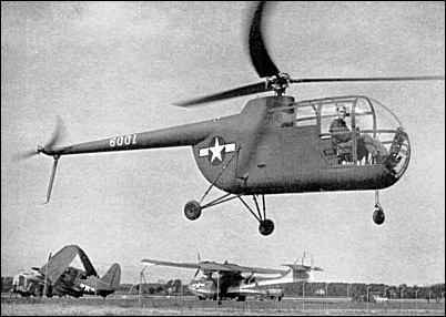
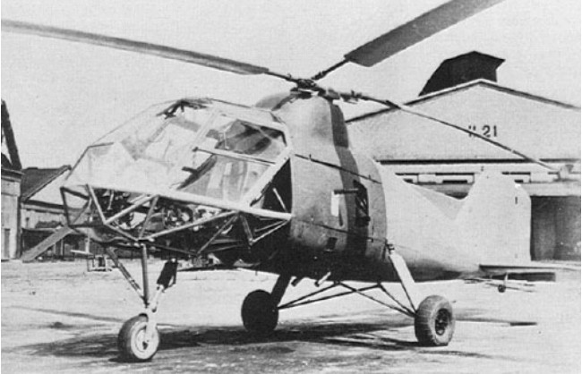
The Flettner Fl 282 Kolibri was designed from the outset as a two-seater, so that, at the expense of range, an observer could be carried, with obvious benefits in the roles of army and navy spotting and anti-submarine work. The observer was to be accommodated in a seat facing rearwards and positioned behind the rotor shafts, and the design provided for a permissible c of G travel which allowed the helicopter to fly with or without the observer without trim changes. The design was finalized by about July 1940 and work began on 30 prototypes and 15 pre-production machines at Flettner’s Johannisthal and Bad Tolz factories. For early flight trials, which began in 1941, the first three Fl 282 prototypes were built as single-seaters and had enclosed Plexiglas-panelled cabins.
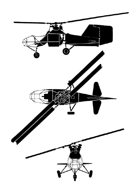
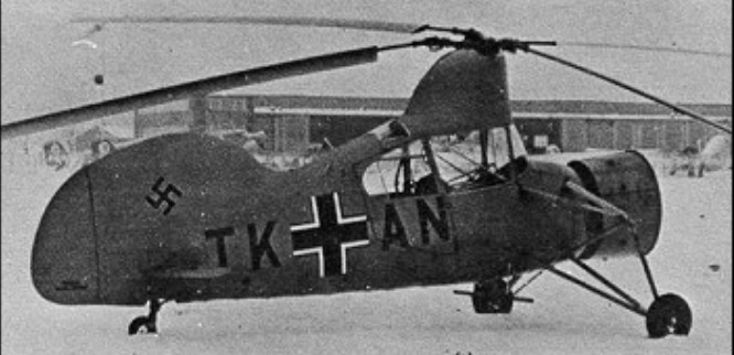
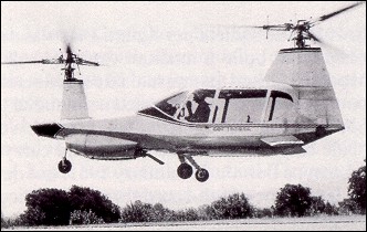
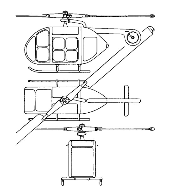
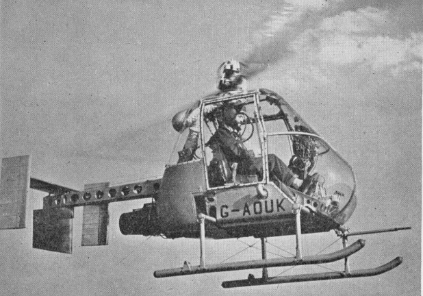
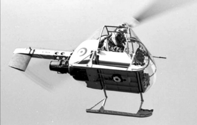
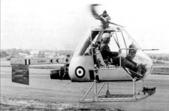
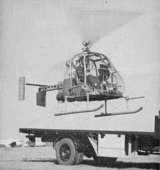
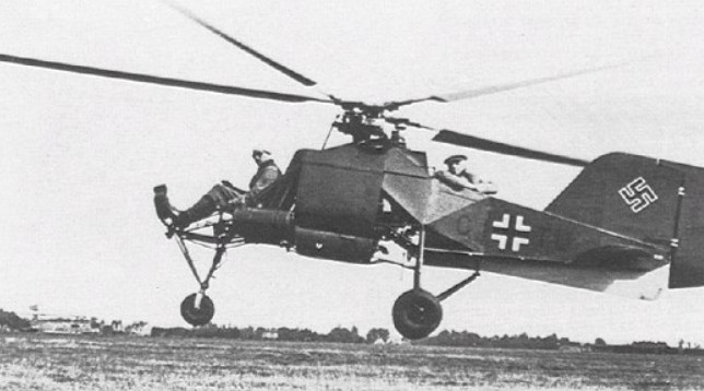
The first three prototypes were completed as single-seaters and had fully enclosed cabins made up of a series of optically flat Plexiglas panels, faired-in rotor pylons and well-contoured fuselages. The Fl 282V3 was fitted with endplate auxiliary fins and a long underfin beneath the rear fuselage. Later two-seater machines had more utilitarian bodies and some had semi-enclosed cockpits; others, like the example illustrated, had a completely open pilot’s seat.
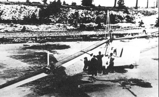
By mid-August 1941 work on the Fl 282 V1 had progressed to the point where it could be used on the ground as a transmission unit test bed. The test bed was anchored but could climb the length of the restraint to a certain height and hover. 125 hours and 39 minutes were spent in these tests, which lasted until November 21, 1941. In the event of the destruction of the V1 or a lengthy interruption of testing due to some other problem, it was planned to use the Fl 282 V4 as a replacement test bed.
For early flight trials the first three Fl 282 prototypes were built as single-seaters and had enclosed Plexiglas-panelled cabins.
The first three prototypes were completed as single-seaters and had fully enclosed cabins made up of a series of optically flat Plexiglas panels, faired-in rotor pylons and well-contoured fuselages. The Fl 282V3 was fitted with endplate auxiliary fins and a long underfin beneath the rear fuselage. Later two-seater machines had more utilitarian bodies and some had semi-enclosed cockpits; others had a completely open pilot’s seat.
The first free flight was made by the Fl 282 V2 on October 30, 1941. At the controls was test pilot Ludwig Hoffmann, who had joined Flettner as the successor to company pilot Perlia. Tests resumed in March 1942 following design changes to the cardan shaft; the tests revealed a significant improvement in the helicopter’s handling. The Fl 282 V2 was taken out of service on May 25, 1942; the aircraft’s transmission and engine were removed for use in other prototypes.
Hoffmann carried out two altitude flights in the Fl 282 V3 on April 27, 1942. On the first he reached a height of 3,500 meters over the takeoff point and on the second (from 1517 to 1610 hours) 3,800 meters in 36 minutes.
The Fl 282 V5, which featured a number of changes compared to the V3 (tail surfaces, fuselage, pilot seat), began flying in January 1942. It also remains to be mentioned that the Fl 282 V2 and V3 had a fully-glazed cockpit. From the V5 on the pilot seat was either entirely open or had a plexiglass shield in front or on the sides.
Various empennage arrangements were also tested. The V3 had a horizontal stabilizer right and left with end fins. A V-shaped stabilizer, similar to that of the Cierva C 30, was installed on the V23.
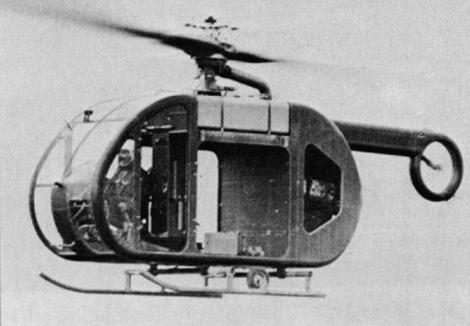
Calculations revealed that reversing the direction of rotation of the rotor should significantly improve directional stability, especially at low power settings. The V8 was rigged up as a test bed to confirm this. Flight tests with the V9 and V15 began in September 1942 and confirmed the theoretical findings. Directional stability was so good, that the entire fuselage section aft of the firewall was simply left off the V9. Flight tests were problem free. The V9 was the prototype for a version to be operated by the Navy from large submarines and designated “Modified Model in Form of a Standing Cylinder” (Fl 282 U).
The Fl 282 was more highly developed and flew more hours than any other German helicopter, and very extensive tests and measurements were made of all flight aspects. Most of this test work was done by Flettner’s chief pilot, Hans E. Fuisting, who also undertook blind flying and trained many of the 50 pilots who learned to fly the Fl 282. Some new pilots ran into trouble when flying near the ground, because, as they turned with the wind, they lost lift and struck the ground. One new pilot had a fatal accident when flying his Fl 282 blind in cloud, and the assumed cause of the accident was that the machine had been dived and the controls then pulled back so violently that the blades were forced into each other or into the tail. The diving speed thereafter was restricted to 175km/h. On occasions, the Kolibri was landed autogyro fashion and without the use of collective pitch. This was done by descending vertically, diving nose-down and then pulling back on the controls to land, but, on one occasion at least, the tail hit the ground and was damaged.
Extremely manoeuvrable and very stable, even in gusty conditions, the machine could be flown hands-off in forward flight above 60km/h for indefinite periods by making an adjustment to neutralize the loads on the controls. However, in forward flight at speeds below 60km/h there was some longitudinal instability which reached a maximum at about 40km/h. Another slight criticism of the Fl 282 was that it vibrated rather badly while the rotor was running up on the ground, but this vibration decreased upon lifting off, although there was still a certain amount of vibration transmitted to the control column, which was sluggish and tended to overshoot the requisite amount of movement. Although many of the mechanical components were unnecessarily complicated and heavy, the general design and workmanship were of excellent quality, and, as an endurance test, one machine was flown 95 hours in all without replacements or repairs. The engine was said to be capable of 400 hours between overhauls.
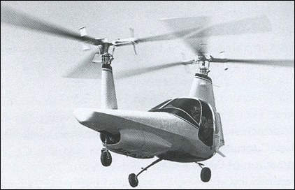
The Fl 282 V21 and V23 were built as two-seaters; an observer sat with his back to the pilot in the fuselage behind the engine block. This made necessary the removal of the fuselage fuel tank; it was replaced by two unprotected, cylindrical tanks mounted externally on both sides of the pilot seat. Furthermore, a different rotor arrangement – two three-blade rotors – was tried out on the test bed. It proved to run extraordinarily smoothly, however this was not a consideration for military use.
The entire Fl 282 flight test program was not conducted at Rechlin, as was customary for land-based aircraft; instead, from August 1942, trials were carried out at E-Stelle See Travemünde. In charge of helicopter and autogiro testing there was Fliegerstabsingenieur Dipl. Ins. Hans Fischer; his assistant was Fliegerstabsingenieur Dipl. Ing. Otto Dumke. After Fischer was badly hurt in the crash of one of the E-Stelle’s Do-217’s, Fliegerstabsingenieur Dipl.lng. Gerhard Geike assumed responsibility for the workings of this group.
Travemünde was selected because the air traffic safety ship Greif was based there and could be used for deck landing trials. The site also simplified helicopter sea trials with the navy, it was also imperative to move the site of the trials from Flettner’s facility in Berlin, where there was a greater risk from the growing Allied bombing raids.
One special experiment took place in cooperation with the DVL’s Institute for Marine Aviation. It involved “towing tests with a 50kg gliding body.” The proposal originated from the director of the Erprobungs- und Lehrkommando (Testing and Instruction Detachment) 20, Hauptmann von Winterfeldt, who carried out the towing flights from an antisubmarine vessel in Gotenhafen on May 3 and 4,1943. In addition to its role as a reconnaissance aircraft in support of the sub-chasers, armed with bombs the Fl 282 was also to participate actively in the anti-submarine role.
The following extract from the E-Stelle Travemunde’s monthly report of June 1944 is also worthy of mention:
“A mock combat between the Fl 282 (Flettner company pilot Fuisting) and a Fw 190 (pilot Ltn. Eisenlohr of E.Kdo.25) took place at Schweidnitz on 22.06.1944, in order to investigate the chances of a fighter hitting a helicopter. At present the evaluation of the film and the pilot reports have not yet arrived. At heights above 100 meters the fighter was able to get the helicopter in its sights briefly. Near the ground, especially in difficult terrain, the fighter has little chance against a helicopter.”
Vulnerability to gunfire was also investigated, whereby they proceeded on the assumption that the mathematical probability of a moving rotor blade being hit was much less than that of a fixed wing. Another consideration was that it should be extremely difficult to fire on and hit the slow-moving helicopter from a fast fighter. The latter could escape by making brief evasive movements, which the fighter could not follow. Furthermore, tests involving ground firing at the moving rotor blades were carried out, as the helicopter was felt to be more vulnerable to gunfire from the ground than from the air. An unmanned, tethered Kolibri was used; in spite of several hits in the rotor blades ground fire failed to bring down the helicopter.
The Fl 282 was more highly developed and flew more hours than any other German helicopter, and very extensive tests and measurements were made of all flight aspects. Most of this test work was done by Flettner’s chief pilot, Hans E. Fuisting, who also undertook blind flying and trained many of the 50 pilots who learned to fly the Fl 282. Some new pilots ran into trouble when flying near the ground, because, as they turned with the wind, they lost lift and struck the ground. One new pilot had a fatal accident when flying his Fl 282 blind in cloud, and the assumed cause of the accident was that the machine had been dived and the controls then pulled back so violently that the blades were forced into each other or into the tail. The diving speed thereafter was restricted to 175km/h. On occasions, the Kolibri was landed autogyro fashion and without the use of collective pitch. This was done by descending vertically, diving nose-down and then pulling back on the controls to land, but, on one occasion at least, the tail hit the ground and was damaged.
Extremely manoeuvrable and very stable, even in gusty conditions, the machine could be flown hands-off in forward flight above 60km/h for indefinite periods by making an adjustment to neutralize the loads on the controls. However, in forward flight at speeds below 60km/h there was some longitudinal instability which reached a maximum at about 40km/h. Another slight criticism of the Fl 282 was that it vibrated rather badly while the rotor was running up on the ground, but this vibration decreased upon lifting off, although there was still a certain amount of vibration transmitted to the control column, which was sluggish and tended to overshoot the requisite amount of movement. Although many of the mechanical components were unnecessarily complicated and heavy, the general design and workmanship were of excellent quality, and, as an endurance test, one machine was flown 95 hours in all without replacements or repairs. The engine was said to be capable of 400 hours between overhauls.
Beginning in 1942 with the Fl 282 V5, the German Navy held a series of trials in the Baltic, the machine behaving well under the worst weather conditions. The Fl 282s in these trials operated from a platform mounted on one of the gun turrets of the cruiser Köln.
The German navy, finding the type extremely manoeuvrable, stable in poor weather conditions, and so reliable that in 1943 about 20 of the 24 prototypes were operating from warships in the Aegean and Mediterranean for convoy protection duties. It was discovered that as pilots gained experience the Fl 282s could be flown in really bad weather, leading to an order for 1,000 production aircraft.
The fuselage consisted of a welded tubular-steel structure with metal panelling enclosing the centre (engine) section and fabric the rear section and vertical surfaces. The undercarriage was of the non-retractable tricycle type with the nosewheel connected to the rudder pedals for steering.
It is known that Luft-Transportstaffel 40, based at Ainring in April 1945, had at least three Fl 282s (and also three Focke Achgelis Fa 223s) at its disposal. It was possibly one of this unit’s Fl 282s that flew Gauleiter Hanke out of besieged Breslau just before the capture of that city.
The great success of the Kolibri, which was even better than the Fl 265, resulted in a production order for 1,000 machines being given in 1944 to the Bayerische Motorenwerke (BMW), which prepared the requisite tooling-up only to have production forestalled by Allied bombing of the Munich and Eisenach works. The Flettner Johannisthal factory was also bombed, and, by the end of the war, only 32 preproduction aircraft in all were completed. Of these, only three were discovered by the Allies in a serviceable condition for testing, the Fl 282 V15 and V23 being taken to the USA and a third machine to the USSR. The remainder having been destroyed to prevent them being captured. Examples known to have survived are the Fl 282 (c/n 28368) at the Cranfield Institute of Technology, and the Fl 282 V23 at the United States Air Force Museum, Dayton, Ohio.
During 1944, when the Fl 282 was considered fully developed, Anton Flettner turned to the design of the Fl 339, using all the experience gained with the Fl 282. The Fl 339, which never got beyond the project stage, was to have been a much larger helicopter weighing some 3,000kg empty, carrying about 20 passengers and being powered by a single engine.
Technical description of the Fl 282 B-0 and B-1 (as of 23.12.1943)
- Purpose: I. Reconnaissance aircraft (land); II. Shipboard reconnaissance aircraft.
- Designation: Fl 282 B-0 (with no cockpit glazing). Fl 282 B-1 (plexiglass glazed canopy).
- Crew: one pilot
- Design: Single-engined helicopter and gyroplane of mixed construction with two rotors.
(a) Fuselage: Welded steel tube, truss-type construction. Forward section with open (B-0) or enclosed (plexiglass] cockpit (B-1). Recess for back-type parachute in rear wall of seat. The fuselage center-section contains the entire power plant, the outer skin consists of removable doors, hoods and panels. Oval cross-section. The rear fuselage is fabric-covered with a rectangular cross-section.
(b) Rotor Blades: A tubular steel spar with riveted-on wooden ribs and plywood skin with fabric covering. Rectangular outline with rounded tips. Attached to rotor head with delta and alpha hinges. Receptacle for balance weight at end of spar (scrap). The axes of both rotors are angled outboard at 12° from the vertical. Seen from above, the right rotor rotates clockwise, the left counterclockwise.
(c) Control Surfaces: No elevator. Two-part horizontal stabilizer with single spar. Tubular steel spar with riveted-on wooden ribs. Plywood leading edge, fabric-covering, cantilever construction. Angle of incidence adjustable between -15 and +5° from cockpit.Rudder: wooden construction, fabric-covered, deflection to 40°. Vertical stabilizer: wooden construction with plywood leading edge and fabric covering, bolted to fuselage frame. No ailerons.
(d) Undercarriage: Braced fixed nosewheel with VDM oil shock-absorber leg, coupled with rudder foot pedals (steerable nosewheel). Nosewheel: EC tire 350 x 150mm. Mainwheels: EC tires 465 x 165mm.
- Power Plant
(a) Engine Type: 1 BMW 314 E. Output: 160hp, compression ratio 1:6.0, rotor reduction ratio: 1:12.
(b) Transmission: Lower transmission flange-mounted on front of engine, in front cooling fan on extended crankshaft. Upper transmission, linked to the lower by a double cardan shaft. Firewall over and behind the engine.
(c) Fuel Tank: An unprotected metal tank located behind the firewall in the aft fuselage, consumable content 105 liters.
(d) Oil Tank: An unprotected 10-liter metal tank flange-mounted on the lower gearbox. Oil content of upper gearbox = 5l.
(e) Type of Fuel: 87 octane aviation gasoline.
(f) Cooling System: Continuous cooling provided by an eight-blade wooden cooling fan with direct drive from the engine. Oil cooler which is switched off for cold-weather operalion.
(g) Control System: Control about all three axes by means of periodic or constant changes in angle of incidence of the rotor blades by means of stick and rudder pedals, to which the rudder is connected. Change-over from helicopter to autogiro (autorotation) flight and reverse achieved by means of a speed-sensitive hydraulic regulator controlled by a hand-operated control lever; change-over to autorotation mode is automatic in the event of engine failure.
- Equipment:
(a) Flight Instruments and Navigation Equipment: 1 airspeed indicator, 1 altimeter, 1 vertical speed indicator, 1 turn-and-bank indicator, 1 RPM indicator for rotors, 1 rotor blade angle indicator, 1 master compass, 1 dash-board clock.
(b) Safety and Rescue Equipment: 1 back-type parachute, 1 first-aid kit, 1 one-man inflatable raft (shipboard reconnaissance version).
(c) Radio and Signalling Equipment: 1 FuG 19 radio installation, 1 rigidly-mounted single-barrel flare pistol, 1 rigidly-mounted signal lamp (shipboard reconnaissance version).
(d) Bomb-Release Mechanism: 1 bomb magazine for two 5kg explosive devices (ship board reconnaissance version). 1 magazine for smoke buoys (shipboard reconnaissance version).
- Special Equipment: Deck-landing equipment, consisting of: 1 tether with landing cable and electrical release.
- Dimensions: Length of aircraft: 6150mm. Width, including undercarriage and tail surfaces: 2400mm. Height with rotor blades removed: 2400mm. Rotor diameter: 12000mm.
- Technical Data: (a) construction group: H 3; (b) maximum allowable flying weight: 1.000kg; (c) wing loading: 8.84 kg/m2 (based on rotor surface area); (d) maximum allowable speeds: as helicopter: forward: 80 km/h, backward: 30km/h, sideways: 20km/h; as autogiro: 60km/h; (e) minimum allowable speeds: as helicopter: no limitations; as autogiro: 40km/h, aerobatic forbidden!
- Performance: (a) Speed: Speed is temporarily limited to 80km/h in horizontal flight in helicopter mode for reasons of structural strength, 60km/h in autogiro mode.
(b) Rate of climb: 4.5m/s at sea level, 3.5m/s at 1000m, 3.0m/s at 1500m. Maximum altitude temporarily restricted to 1500 meters for flight safety reasons.
(c) Takeoff and Landing Performance: Takeoff and landing are made vertically. Autorotation landing in event of engine failure. Landing distance from height of 20m: 50m, stopping distance 15m (with wind speed of 5m/s).
- Range: Endurance of 2 hours 5 minutes at maximum allowable speed of 80km/h and a range of 168km. The “Technical Description Fl 282 B-0 and B-1” presented above was prepared with the Fl 282 V12.
Flettner FL 282 Kolibri
Engine: Bramo Sh 14A radial 7 cylinders, 160 hp
Speed: 150 km/h
Service Ceiling: 3300 m
Range: 170 km
Empty weight: 760 kg
Max weight: 1000
Width: 25.55 m
Length: 6.56 m
Height: 2.20 m
Rotor Span: 11.96 m
Disc Area: 224 sq.m each
Fl 282 V21
Engine: 1 x Bramo Sh.14A 7-cylinder radial, 119kW
Rotor diameter: 11.96m
Fuselage length: 6.56m
Height: 2.2m
Max take-off weight: 1000kg
Empty weight: 760kg
Max speed at sea level: 150km/h
Hovering ceiling: 300m
Service ceiling: 3300m
Range with one pilot: 300km
Range with full crew: 170km