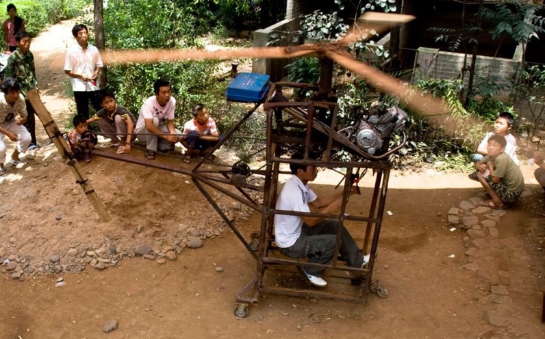
20-year-old Wu Zhongyuan, a farmer from Henan province. He has since childhood dreamed of flying and spent three months and $1,600 building a shanzai helicopter. The airframe is fabricated from a steel scaffold. Power comes from an old 150cc motorcycle engine driving Elm wood blades. Zhongyuan claims the chopper will fly to 800 meters (2,600 feet), but so far hasn’t been able to prove it.
Provincial authorities have forbidden him from flying on safety grounds.
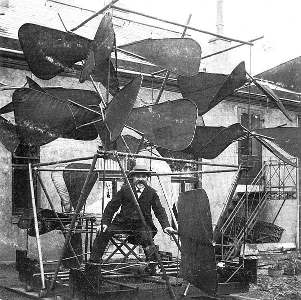
Carl Zenker, of Bremen, Germany, designed this “steerable airship” Eight horizontal propellers provided vertical lift. Its construction from bamboo rods and cloth took from August 1873 till March 1900, and cost about 40,000 Marks. Herr Zenker stated proudly that the craft, “Requires no balloon to become airborne, and operates at a nominal 6hp”. Weighing 660lb and driven by “fluid air and compressed air”, a speed of 1km in 2mins (about 18.5mph) was estimated. Horizontal flight was to be achieved by means of twin propellers, and the craft was steered by a single rudder. One could own a Zenker contraption for a mere 10,000 Marks, from four to six months after receipt of the order.
In 1928 Zaschka carried out experiments with a two-rotor helicopter at Tempelhof Airport in Berlin.
“His [Engelbert Zaschka’s] plane, the first helicopter, which ever worked so successfully in miniature, not only rises and descends verticially, but is able to remain stationary at any height. Herr Zaschka is fully aware that the perfection of his invention will be the greatest forward step in aviation since the Wright brothers made their historical hop. As he pointed out, the danger of flying would immediately be decreased by at least 80 per cent, since four fifths of the accidents in flying occur either in the takeoff or in landing. […] A motor giving thirty to forty horsepower is installed in Zaschka’s present experimental machine. It is so delicately adjusted that he has been able to keep the plane at a height of several feet above the ground, with no movement either up or down.”
Source: German Plane Promises New Stunts in Air, The Bee. Danville, Virginia, USA, June 25, 1927, p. 16.
The Zafar 300 is an Iranian attack helicopter based upon the American Bell Model 206A Jetranger utility helicopter, adapted for a military gunship role. It is armed with a General Electric GAU-2B/A Minigun rotary six-barrel machinegun in an under-nose turret, and disposable stores on two hard points. The Zafar 300 is manned by a crew of two comprising a pilot and gunner seated in tandem.
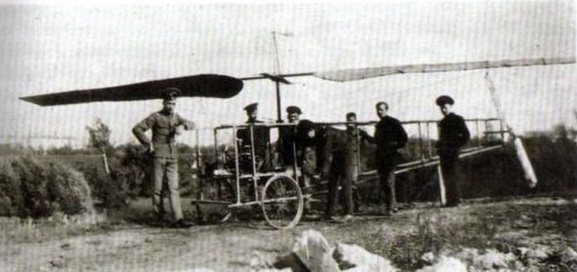
Student of the Moscow Technical College (МВТУ), Борис Николаевич Юрьев (Boris Nickolaevich Yurev) was the inventor of an automatic pitch-control mechanism, but because of lack of funds this full scale model was built without an engine nor pitch-control mechanism. Later however, a 30 hp Anzani radial was installed yet the machine remained without the poorly working pitch-control, which was used only on rotating tests. Considered to be the first modern helicopter with a single main rotor and a tail rotor.
Circa 1922 J.J.Young built a single place coaxial rotor helicopter. The rotors consisted of carved propellers driven by a rotary engine. It is not known if the machine was flown.
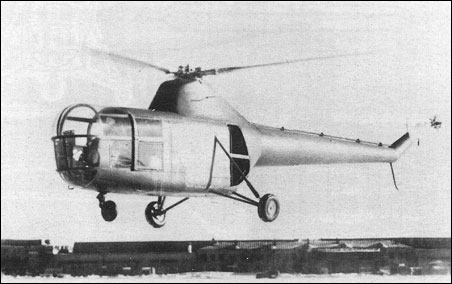
Yakolev ordered the development of a practical helicopter capable of being built in two forms, as a transport carrying a pilot and two passengers, or equivalent cargo, and as a two-seat, dual-control trainer. Design began in June 1947, this machine being one of several which were given out-of-sequence type numbers. The Yak-100 was externally similar to the Sikorsky S-51. The OKB team, under Erlikh, designed this single-rotor machine retaining similar dynamic parts the to EG. The drive and hub mechanism with damped flapping, feathering and drag hinges and hydraulic-dashpot control via swashplate were similar with three main blades of hardwood and pine as before, with ply skin and glued fabric overall. Root of each blade in upper/lower halves of bolted D1, steel hub. Main change in engine installation was vertical engine mount with several changes to enable engine to run in this attitude. Cooling fan, clutch/freewheel and reduction gear and angle box for tail rotor were more Sikorsky than scaled-up EG, though pilot controls and control system retained OKB belief in spring and oil vibration dampers (this time with pilot adjustment) and in spring-loaded actuation of pitch into autorotation following loss of drive torque. Pedal control of tail-rotor pitch. Airframe based on welded steel-tube frame carrying landing gear, seats, rotor hub and engine. Skin riveted D1, and cranked tailboom D1 monocoque. Basic design completed late 1947 as tandem trainer or as transport with single pilot in front and two-seat divan or other payload behind.
The engine was Ivchyenko’s AI-26 seven-cylinder radial, the version chosen being the 575hp AI-26GRFL designed to operate with crankshaft vertical. This drove via a cooling fan and centrifugal clutch to a main gearbox which turned the single main rotor at 232 (not 233) rpm, with a bevel drive to a shaft carried on external trunnions along the top of the long tail boom to a 2.6m three-blade tail rotor. The latter counteracted the main-rotor drive torque and provided yaw (directional) control, driven by pedals. Both rotors were again of fabric-skinned wood laminates, the main rotor having manual control via swash-plates, with spring-loaded automatic autorotative control following loss of drive torque.
The fuselage was again based on a welded-tube truss, with unstressed D1 skin, but the tail boom was a D1 semi-monocoque. The main gearbox was housed in a large mast fairing above the engine compartment, with a front air inlet for the fan-assisted oil cooler. Again the undercarriage was a simple tricycle, with a castoring levered-suspension nosewheel and triangular-braced main units with oleo shock struts pinned to the upper longerons. Track was 3m and wheelbase 2.865m. The entire front of the fuselage was transparent, with sliding doors on the right for the pilot and on the left for the backseater (who had dual control in the first prototype). The transport version was to have a two-seat divan at the rear.
Two prototypes built, first with VVS funds and bearing VVS insignia. The first prototype was tested from November 1948. Initially suffering from severe vibration and apparent blade flutter, the lades given ground-adjustable TE tabs and eventually modified with CG further aft, behind flexural axis. These blades first fitted to No.2 Yak-100, which began test July 1949. Gradually problems with vibration and flutter were solved, and a second prototype was built with modified blades with the cg behind the flexural axis which greatly improved behaviour without complicated damper systems. This dubler, first flown in July 1949, had a more-fully enclosed engine bay with grilled panels and an internally mounted tail-rotor drive shaft. NII-VVS testing took place in the second half of 1950.
Factory test complete June 1950 and NII tests successfully accomplished later same year, but Mi-1 already adopted and Yak-100 project was lost dropped.
The Yakolev OKB started development of helicopters after the war and designed an experimental machine in 1946, the Yak-EG (Eksperimentalnyi Gelikopter) with a coaxial rotor system, and widely known as the Yak-M11FR-1. The chief engineer was S.A.Bemov, assisted by I.A.Erlikh. From the outset it was planned as the smallest practical machine to solve basic problems. The engine was a 140hp M-11FR-1 mounted in the normal attitude with the drive taken through a cooling fan and centrifugal clutch to a 90deg bevel gearbox to co-axial vertical shafts. These turned two-blade rotors in opposite directions, at 233 rpm. After studying the possible use of pilot controlled tabs or auxiliary surfaces behind the blade tips the choice was a fully articulated hub with swashplates giving collective and cyclic pitch control. A unique feature was a spring-loaded hydraulic coupling which, upon failure of the drive torque, automatically moved the collective linkage to autorotative pitch. The rotor blades were laminated pine and hardwood, covered in glued fabric, held in a hub of steel and duralumin. The fuselage was a simple truss of welded steel tube, with Dl skin as far back as the rear of the engine compartment, where an aft-facing gap allowed fan-induced cooling air to escape. The fuel tank was under the main gearbox and the oil tank next to the engine. For better stability in cruising flight a light fabric-covered rear fuselage with twin fins and a tailskid was added behind this point. The welded truss was extended at the front and sides to three vertical shock struts with single wheels, the nose unit having levered suspension. Track was 2.8m and wheelbase 2.68m. The side-by-side cockpit had a door on each side and the largest possible window area. The Sh was completed in early 1947. The chief pilot was V.V.Tezavrovskii, who with others made forty tethered tests (total 5hr) followed by seventy-five free flights (total 15hr). Ground resonance, then little known, was avoided by pure chance. The centre of gravity was clearly too far aft, so the tail (and for a time the tail-skid) were removed and the oil tank relocated behind the cockpit bulkhead. Eventually the Sh hovered under good control, but as soon as forward speed exceeded about 30km/h vibration and progressive loss of control were encountered. Following testing it was decided that the coaxial rotor layout should be developed by the Kamov bureau, and Yakolev moved on to other helicopter configurations.
EG Engine: M-11FR-1 5-cylinder air cooled piston, 140 hp Rotor diameter: 10.0m Length: 6.53m Max take-off weight: 1020kg Empty weight: 878kg Payload: 142kg Fuel: 50kg Max speed at sea level: 150km/h Max speed reached: 70km/h Hovering ceiling: 250m Service ceiling: 2700m Service ceiling reached: 180m Range: 235km
Soviet rotorcraft development was suspended during World War 2, and it was not until late summer 1952 that the USSR made its first major effort to close the design gap between itself and the USA in regard to large transport helicopters. In response to order of Stalin at a Kremlin meeting autumn 1951, two basic projects were selected, the first, for a 12-passenger machine of single main rotor configuration, being assigned to the Mil design bureau. The second, entrusted to the bureau headed by Aleksandir S. Yakolev, was for a twin-engined, tandem-rotor machine capable of seating 24 passengers. Prototype flights of both types were required to take place within one year.
Mil had already prepared suitable design, and Yak gained permission to use essentially same main rotor and drive from similar engine, merely doubling up to use two engine rotor systems at ends of boxcar fuselage. Yak assembled a large team including Erlikh, veteran helicopter man N.Skrzhinskii, P.D.Samsonov (famed flying-boat designer who had long managed Yak prototype dept), L.Shekhter, L.S.Vil’dgrub and many other well-known engineers. The plan was to build four four Yak-24, already called LV (Letayushchii Vagon, flying wagon), two for static and resonance test and two for flight. Yakolev was promised “unlimited support” for the rush programme.
A S Yakolev has described how, in autumn 1951, he and other designers were called to the Kremlin and told by Stalin to create two helicopters, one to carry a useful load of 1,200kg or twelve armed infantry and the other just twice as much, prototypes to be ready in one year. It was to be a ‘crash programme’, with ‘unlimited support’ from the national research institutes. Nobody was eager, but eventually Mikhail L Mil agreed to tackle the smaller machine and Yakolev the larger, Yakolev having the idea of simply using tandem rotors based on those of the Mil’ design.
Designing the Yak-24 started in December 1951. Though the first prototype was built extremely quickly, this programme was to prove more protracted than any previous endeavour by the OKB. Including later versions the chief engineers comprised I A Erlikh (the original leader) and P P Brylin, Yu I Orlov, V P Lashkov, G I Rumyantsev and G I Ogarkov.
Mil, with CIAM, CAHI and other organizations, including Shvetsov’s engine KB, developed the rotor and its drive system. The engine was the ASh-82V, a special helicopter version of the fourteen-cylinder radial used in some Yak fighter prototypes. Rated at l,430hp, and with 1,700hp available for takeoff, it was developed with a cooling fan and centrifugal clutch and cleared to operate in any attitude. It was decided to install the front engine between the cockpit and cabin at an angle of 60deg to drive the gearbox under the front rotor. The rear engine was installed in the normal attitude in the base of an enormous rear fin which formed the pylon for the rear rotor, driving through a 90deg bevel gearbox.
The rotors had fully articulated hubs made of D16 and steel, with drag and flapping hinges and friction dampers. In fact, the rotor was not identical to that of the Mi-4, and indeed later Mil enlarged his rotor by using Yakolev’s longer blades. The four blades were tapered, with NACA-230 profile, based on a 30KhGSA spar with ply ribs and skin covered in varnished fabric, with tracking adjusted by a tab on the trailing edge near the tip. The fabric was replaced by a steel rotor with a metal skin on the production models. The rotors turned at 178 rpm in opposite directions, the rear rotor being a mirror image of the front rotor which it over-sailed. The gearboxes were linked by a torque shaft so that flight could just be maintained on one engine. Each engine was geared to drive one or both rotors. Unfortunately this arrangement, although intended as a precaution against failure of either engine, created the problem of ‘sympathetic’ vibration. From the outset, vibration hampered the Yak-24’s development.
The boxcar fuselage was based on a truss of welded KhGS A tube, originally fabric-covered, then skinned with unstressed Dl panels covering the engine bays, rotor pylons and fin, and by fabric elsewhere. Each engine was housed in a fire-resistant bay with large apartures for cooling air, those for the rear engine being forward-facing open inlets beside the fin leading edge. Each engine had its own fuel tank. At the front was the fully glazed cockpit for two pilots and a radio operator/engineer, with a sliding door on each side and a rear door to the engine compartment, through which a narrow passage led to the main cabin. Aluminium plank cargo floor with full-section access via rear ramp/door; passenger door forward on left side.
Rear rotor mounted on top of vertical fin (TE curved to right to give side-thrust to left in flight) with drive from engine installed in normal horizontal attitude at base of fin, with open cooling-air inlets each side of fin and clearance under engine for vehicles and other cargo on ramp. High-speed connecting shaft to front rotor, mirror-image with rotation anti-clockwise seen from above, driven by engine at 60° angle between cockpit and cabin. Nose cockpit for two pilots, radio-operator and engineer, entirely glazed with aft-sliding door each side and sliding door(s) at rear giving restricted access past engine to main compartment. This measured 10m long, the cross section being 2m square with intended accommodation for up to 40 troops on canvas wall seats or light vehicles or 4t cargo, with crane operation using central hook on underside of fuselage. There were six windows on each side, one being in a door, and at the back was a full-width ramp door through which shallow loads such as a GAZ-69 ‘Jeep’ could be moved under the rear engine on to the floor of aluminium planks. Four similar levered-suspension wheel landing gears, each normally castoring +/-30 deg, on rigid welded steel-tube outriggers. The track was 5m.
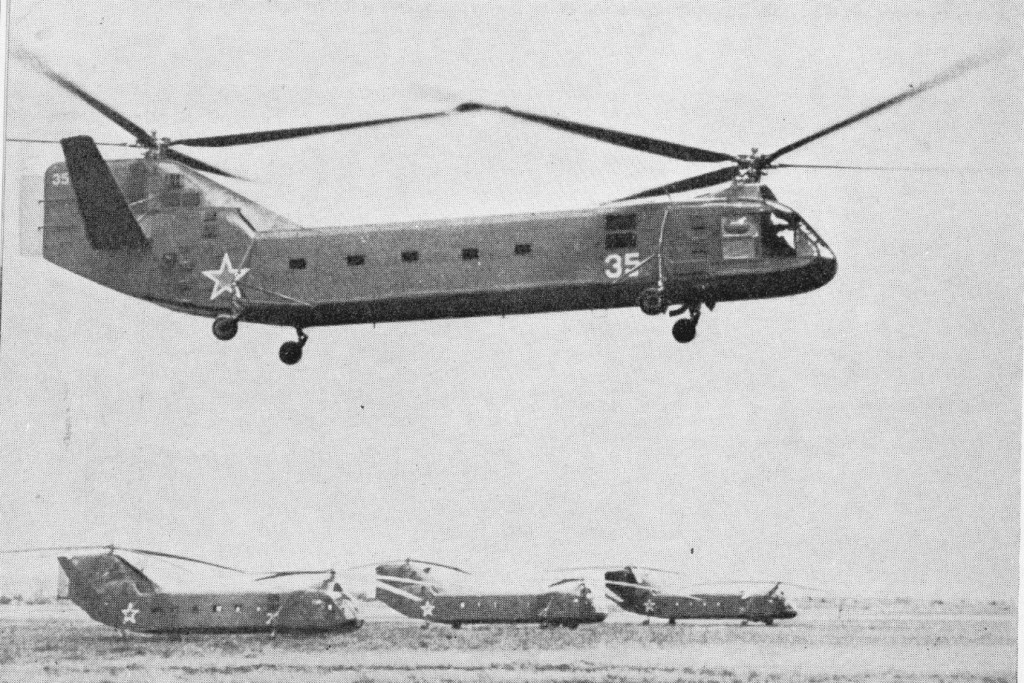
Two flying prototypes completed, and two others were built for static and dynamic testing. While numerous establishments tested complete engine/rotor rigs, blade fatigue and truss structure of fuselage, first flight article readied spring 1952 and began 300 hr endurance test with wheels tied down. Vibration in evidence from start, and usually severe. With greater experience OKB might have recognised a fundamental N1 main-rotor mode and altered critical dimension. As it was, at 178th hour, rear engine tore free from fatigued mounts, machine being destroyed by fire. Second flying article, ie, 4th airframe, finally began tethered flight piloted by Sergei Brovtsev and Yegor Milyutchyev 3 July 1952. Hops at partial power were followed by full-power flights, when vibration reared its head dangerously. Five months by every available expert found no cure; then Yakolev personally ordered 0.5m cut off each main-rotor blade, reducing diameter from 21m to 20m. This effected immediate great improvement. No.4 aircraft delivered for NII test Oct 1953, but destroyed when tethers snapped during ground running. OKB delivered improved aircraft with numerous mods including modified tail with no fins but braced tailplanes with dihedral 45°. This finally passed NII April 1955 and production began at GAZ in Leningrad. With official tests completed on later prototypes, production began in April 1955, and only four months later evaluation aircraft were demonstrated at Tushino airport during the Soviet Aviation Day display. The first four pre-series Yak-24 (visibly not all identical) flew at Tushino, Aug 1955.
Final development work on the aircraft was extremely long and complex and full-scale production for the armed forces began in 1955, about 30 months behind schedule.
Series version had strengthened floor with tracks for vehicles, tie-down rings, attachments for pillars carrying 18 stretchers, full radio and night equipment and facilities for field servicing. Normal max load 20 armed troops or 3t.
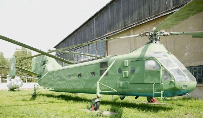
The early Yak-24’s featured a Vee tailplane, but later production examples had rectangular endplate fins on a horizontal tailplane, and both have been seen with and without a narrow auxiliary rudder.
Production was ordered at a Leningrad factory, where thirty-five were built for the VVS in 1956-58. These were painted in dark green camouflage, and except for the first few had larger tailplanes with dihedral reduced to 20deg carrying large endplate fins set at an angle of 3deg 30′ to give the required thrust to the left in cruising flight, the tail end no longer being curved to the right. They had full equipment for loading and securing vehicles and other cargo up to a maximum of 3,000kg. Canvas wall seats were provided for twenty troops, with racks for weapons and equipment, with pillar sockets for eighteen stretchers accompanied by an attendant. A three-tonne load could also be slung from a central hook, but on 17 December 1955 Milyutichev carried an overload of four tonnes to 2,092m. On the same day G A Tinyakov set a second world record in the same prototype by taking 2,000kg to 5,032m.
At an air display in Moscow in July 1956 the Yak 24 made its first appearance.
Yak-24U (Uluchshennyi, improved) flew Dec 1957 with numerous mods resulting from prolonged research. Rotor blade length unchanged but diameter restored by adding long tubular tie at root. Side-thrust at tail reduced by canting axes of rotors 2°30′ (front to right,, rear to left), so curved rear of fin removed. Fuselage frame strengthened, metal skinned throughout and cabin increased in width 0.4m. Flight-control system fitted with two-axis autostab and autopilot of limited authority, developed within OKB. External slung load attached to winch in roof of cabin with large door in floor. Rear landing gear oleos changed in rate to eliminate last vestiges of ground resonance, and other minor changes including revised fuel system.
In production GAZ-33 early 1959, though halted at No 40. This variant could at last lift 40 troops or 3.5t and at least some production machines had tailplane dihedral 0°.
In January 1958 a complete three-axis autostabilization system was cleared for service and retrofitted to each helicopter. This dramatically improved stability and control, making hands off hovering possible. The USAF called this helicopter ‘Type 38’, later replaced by the ASCC name ‘Horse’.
Initial Yak-24 production was undertaken on behalf of the Aviatsya Vozdushno-Desantnich Voisk (Aviation of the Airborne Troops), in which configuration the aircraft could accommodate up to 40 fully-equipped troops according to range. Other typical loads of the “Letayuchiy Vagon” (Flying Wagon), as it was quickly dubbed, include 18 casualty litters, 2 anti-tank guns, 2 GAZ-69 command vehicles or 3 M-20 staff cars. In 1958 the Yak-24U became the standard military model, with all-metal rotor blades and fuselage skin, the revised tail configuration already mentioned, and the rotors restored to the original 21.00m diameter.
Yak-24U This Uluchskennyi (improved) helicopter was completed in December 1957, and tested from January 1958. The rotor blade spars were connected to the hub by oval-section steel tie rods at the root, restoring rotor diameter to the original design value. The axes of the rotors were canted 2deg 30′, the front hub tilted to the right and the rear to the left, so that the entire tail could be redesigned for minimum drag without the need to generate side thrust. Avionics included a two-axis autostabilization system and limited-authority autopilot developed mainly within the OKB. The fuselage truss was strengthened and increased in width by 0.4m and made slightly higher, and metal-skinned throughout. The external slung load rating was increased to 3,500kg, and the cable passed through a large floor hatch to a winch in the roof of the cabin. The rear landing oleos were modified to eliminate any tendency to resonance (now a better understood phenomenon), and later the fuel system was improved and the capacity significantly increased. This prototype could carry thirty-seven armed troops, but its main use was as a crane, putting roof trusses on the Pushkin (Ekaterinskii) palace and carrying gas pipes from Serpukhov to Leningrad over impassable marsh.
One example built by 1960 of Yak-24A (designation from Aeroliniya, airline) similar to late Yak-24U with horizontal tailplane and latest avionics but with comfortable civil interior for 30 passenger seated 2+1. Continious glazing down sides of fuselage, compartment for 300kg baggage and the rear freight door eliminated. Appeared in Aeroflot markings though never in service. The passenger door on the left was fitted with fold-down steps, and the cabin was fitted with larger windows.
Aeroflot (the Russian state airline) evaluated the Yak-24A commercial version, but turned it down. The Yak-24A can also be operated as a freighter or flying crane, being able to lift an external sling load of 5000kg. It also rejected the 1960 Yak-24K deluxe short fuselage version for 8-9 passengers. The fuselage was shortened, fitted with even bigger windows, improved soundproofing and heating and an electrically-operated airstairs, and luxuriously furnished for nine passengers. The Yak-24P for 39 passengers, with two 1500shp Isotov turbines mounted above the cabin was never built.
The Yak-24UB, flown in December 1957, included many design improvements and was placed in production from 1959, about 50 being delivered; this version could carry 40 fully equipped troops or up to 3500kg of cargo.