Olympus 140 Wing area: 12.9 m² Wing span: 9.9 m Aspect ratio: 7.83 Hang glider weight: 22 kg Minimum pilot weight: 50 kg Maximum pilot weight: 65 kg Packed length: 5.75 m Packed length short: 3.5 m Number of battens: 14 Nose angle: 121°
Olympus 160 Wing area: 14.86 m² Wing span: 10.5 m Aspect ratio: 7.65 Hang glider weight: 24 kg Minimum pilot weight: 65 kg Maximum pilot weight: 80 kg Packed length: 6 m Packed length short: 3.5 m Number of battens: 14 Nose angle: 121°
Olympus 180 Wing area: 16.6 m² Wing span: 10.75 m Aspect ratio: 7.2 Hang glider weight: 24 kg Minimum pilot weight: 80 kg Maximum pilot weight: 100 kg Packed length: 6.15 m Packed length short: 3.5 m Number of battens: 14 Nose angle: 121°
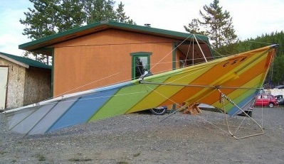
Designed primarily by Tom Price (with some input from Tom Peghiny and Larry Newman) and released in 1979, the Floater was Electra Flyer’s first attempt at a glider to compete with the Moyes gliders and La Mouette’s Atlas, both of which employed light wing loading to achieve a low sink rate while still offering some glide at speed. While it achieved both goals, it turned out not to be competitive with its rivals. It remained in production for a year, being replaced with a somewhat smaller version called the Spirit which, while it did not have the Floater’s sink rate, was more maneuverable and easier to fly.
The largest size Floater was a popular tandem glider in the early 1980s.
Floater 165 Wing area: 15.3 m² Hang glider weight: 24 kg Minimum pilot weight: 45 kg Maximum pilot weight: 70 kg Minimum speed: 29 km/h Max glide ratio (L/H): 7.5 Minimum sink rate: 1.15 m/s Number of battens: 24
Floater 185 Wing area: 17.2 m² Hang glider weight: 25 kg Minimum pilot weight: 60 kg Maximum pilot weight: 80 kg Minimum speed: 29 km/h Max glide ratio (L/H): 7.5 Minimum sink rate: 1.15 m/s
Floater 205 Wing area: 19 m² Hang glider weight: 26 kg Minimum pilot weight: 70 kg Maximum pilot weight: 90 kg Minimum speed: 29 km/h Max glide ratio (L/H): 7.5 Minimum sink rate: 1.15 m/s
Floater 235 Wing area: 21.8 m² Hang glider weight: 30 kg Minimum pilot weight: 80 kg Maximum pilot weight: 100 kg Minimum speed: 29 km/h Max glide ratio (L/H): 7.5 Minimum sink rate: 1.15 m/s
The 1980 Dove was intended as a successor to the Cirrus 5, without deflexors but with a sail cut to compensate for the leading edge’s bend under load. For its time, it was a decent “floater” but didn’t have the speed range of the Cirrus models. Since it was lighter than most gliders of the time, it found some use as a trainer for novice pilots.
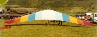
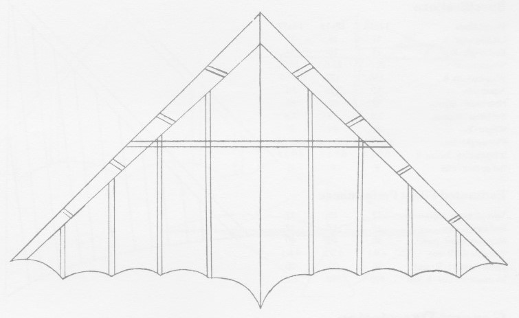
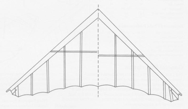
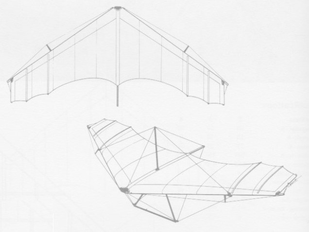
The Nimbus series is an intermediate advanced Rogallo. It was the first production glider to incorporate full length battons.
No tools are required for set-up or take-down. All rigging bolts and kingpost wires are removable in the event of damage.
The airframe is made from 6061-T6 1.5in x .049 (.058 for towing) clear anodised aluminium throughout. The tubing ends are capped with solid aluminium plugs to prevent crushing.
The rigging is 3/32in 7×7 stainless steel coated double nico swedged. The outrigger cables are 1/16in 1×19 stainless steel. The kingpost wires have a cam operated quck release system.
All nuts and bolts are aircraft quality and all parts are gold and black anodised.
The sail is mde from 3.8oz stabilised dacron in a choice of 11 colours. The 1/4in x 3/4in plastic battens (total weight 1 lb) are held in place with industrial elastic and take 75 seconds to install. A swing seat came with seated/prone adjuster.
19×16 Leading edge: 19 ft Keel length: 16 ft Wing span: 27.5 ft Wing area: 180 sq,ft Aspect ratio: 4.2 Nose angle: 91˚ Sail billow: 2.95˚ Weight: 36 lb Pilot weight: 110-145 lb Takeoff speed: 12 mph Stall speed: 12 mph Max speed: 40 mph Best glide ratio (L/D): 6.1-1 Best L/D speed: 23 mph Min sink: 350 fpm
20×17 Leading edge: 20 ft Keel length: 17 ft Wing span: 29.5 ft Wing area: 195 sq,ft Aspect ratio: 4.46 Nose angle: 91˚ Sail billow: 2.95˚ Weight: 38 lb Pilot weight: 140-180 lb Takeoff speed: 12 mph Stall speed: 12 mph Max speed: 40 mph Best glide ratio (L/D): 6.1-1 Best L/D speed: 23 mph Min sink: 350 fpm
20×19 Leading edge: 20 ft Keel length: 19 ft Wing span: 29 ft Wing area: 215 sq,ft Aspect ratio: 3.82 Nose angle: 90˚ Sail billow: 3˚ Weight: 39 lb Pilot weight: 150-210 lb Takeoff speed: 12 mph Stall speed: 10 mph Max speed: 40 mph Best glide ratio (L/D): 5.5-1 Best L/D speed: 22 mph Min sink: 375 fpm
A high speed performance glider, the Cirrus features diffused leading edges, ram air injected tapered leading edge pockets which create an airfoil, and full batten sails. It has a quick response. Broad speed range, stability at low speeds, and mild stall characteristics. It was designed for the Hang III pilot.
The Cirrus can be converted for towing. No tools are requires for set-up or take-down.
The airframe is made of 6061-T6 1.5in x .049 clear anodised aluminium throughout. Tubing ends are capped with solid aluminium plugs to prevent crushing. Rigging is 3/32in 7×7 stainless steel vinyl coated nico swedged. Out rigger cables are 1/16in 1×19 stainless steel. A cam operated quick release system for kingpost wires is fitted.
All nuts and bolts are aircraft quality and all parts are gold and black anodised. The pilot support is a “Backsaver” prone harness.
The sail is 3.8oz stabilised dacron in a choice of 11 colours, fitted with aluminium and plastic ribs.
It was one of the first gliders with battens. They were made of flexible plastic strips, and kept the sail from flapping.
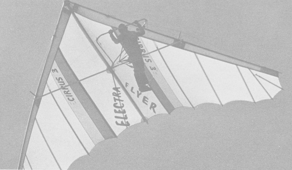
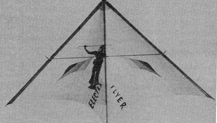
Cirrus 3
The 1976 Electra Flyers Cirrus 3 was very tough in turn, with considerable roll-over loss. The 3 deflexors settings were very important to give the correct contour in flight. But if the wing landed on the ground they bent or often broke.
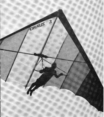
Cirrus 5B
The Cirrus 5 was introduced in 1977 in four sizes, with the C5A being the largest and the C5D being the smallest. The C5B had a keel pocket and six flexible battens per side. Although designed for the novice pilot, it was quite tail-heavy and inclined to tip-stall during low-speed turns. Its handling and sink rate did not approach that of the Olympus, but it had better penetration at speed. Manufacture was discontinued in 1981.
Cirrus 2 Leading edge: 20 ft Keel length: 13 ft Wing span: 31 ft / 9.15 m Wing area: 195 sq,ft / 17.9 sq.m Aspect ratio: 5.63 Nose angle: 98˚ Sail billow: 1.25˚ Weight: 42 lb / 19 kg Pilot weight: 180-225 lb / 80-100 kg Takeoff speed: 10 mph Stall speed: 10 mph / 10 kph Max speed: 47 mph Best glide ratio (L/D): 8:1 Best L/D speed: 25 mph Min sink: 250 fpm Number of battens: 12 Packed length: 5.8 m
Cirrus 3 Leading edge: 19 ft Keel length: 13 ft Wing span: 28 ft / 8.54 m Wing area: 180 sq,ft / 16.5 sq.m Aspect ratio: 4.35 Nose angle: 91˚ Sail billow: 1.25˚ Weight: 39 lb / 18 kg Pilot weight: 135-190 lb / 60-85 kg Takeoff speed: 10 mph Stall speed: 10 mph / 16 kph Max speed: 50 mph Best glide ratio (L/D): 8:1 Best L/D speed: 26 mph Min sink: 250 fpm Packed length: 5.8 m Number of battens: 12
Cirrus 4 Leading edge: 20 ft Keel length: 9 ft Wing span: 31 ft Wing area: 120 sq,ft Nose angle: 98˚ Sail billow: 1˚ Weight: 40 lb Pilot weight: 150-190 lb Takeoff speed: 10 mph Stall speed: 10 mph Max speed: 47 mph Best glide ratio (L/D): 8.5:1 Best L/D speed: 25 mph Min sink: 235 fpm
Cirrus mini Wing area: 14.77 m² Wing span: 8.1 m Aspect ratio: 4.61 Hang glider weight: 17 kg Minimum pilot weight: 40 kg Maximum pilot weight: 60 kg Minimum speed: 16 km/h Max glide ratio (L/H): 8 Packed length: 5.6 m Number of battens: 12 Nose angle: 91°
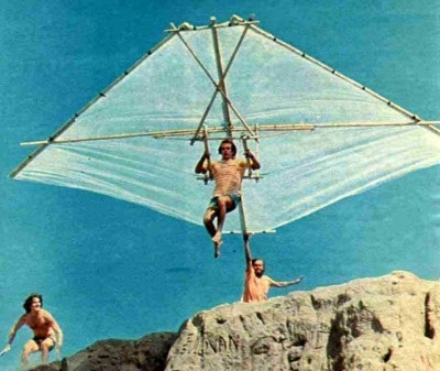
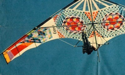
The wing is a version of the Bat-Glider with changes for sure. Taras Kiceniuk made a Batso version with a change from Bat-Glider (published plans by Jim Foreman….which themselves were developed from photos and notes given Foreman by Richard Miller of Millers’s earlier Bamboo Buttfly). Eipper’s Penninsula Hang Gliding crew made the bamboo and polyethelene glider to fly off the Torrance Beach sand cliffs in 1971. Materials used: bamboo canes, string, sillage bags type polyethylen sheets…
Built by Dick Eipper, Ken Seinmetz, and Chris Parker out of bamboo, visquine (a heavy polyethelene sheeting) and plastic coated clothes line…materials purchased by Dick.
That was the summer or 69. That’s Dick Eipper as the pilot, Mark Tolar as the one at the keel and Steve Wilson on the left side of the glider. A few months later Dick and Steve founded EipperFormance Hang Gliders. Ayear and a half later they incorperated and brought Dave Muehl, Mike Hutter, Bob Lovejoy and Dave Cronk on as partners.
These sand cliffs were quite close to the water’s edge at Torrance Beach in Southern California and the water was the objective although they rarely made it that far. Smaller bodies sometimes did. It had no battens but surely needed them as the trailing edge flapped alot and made quite a noise. They didn’t think of it. There were also a few quite spectacular crashes, Steve Wilson, being one of them. He came up with torn Levis, scrapes and bruises, and a face full of sand. That’s why they chose that spot it had all the right characteristics…..soft, or relatively so, landing area and good onshore winds.
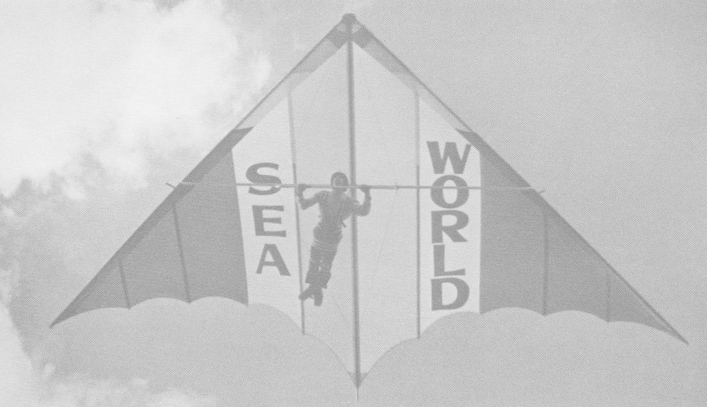
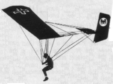
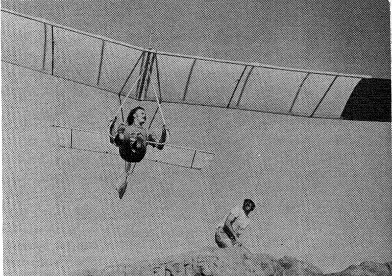
The High-Tailer, designed by Bob Lovejoy, had a height of 1.2 meters and a wingspan of 9 meters. The High-Tailer had two inclined vertical fins starting from the control bar and passing through the trailing edge of the wing (almost identical to the Quicksilver) and finished above the wing. A horizontal plane connected the two drifts.
The design had some directional control problems (it would almost always fly straight ahead, very stable), and the control bar/vertical/horizontal arrangement was somewhat flexible. It was a four sides parallelogram structure, so had little inherent stiffness.
The origin of the Quicksilver can be found in Bob Lovejoy’s High-Tailer design. The High-Tailer and early Quicksilvers all had a 4 foot chord and 30 ft span.
The original Quicksilver (later called the “A” model) was built from the High-Tailer. The twin verticals and high mounted horizontal were replaced with an “A” frame off the trailing edge of the wing, back to a fixed horizontal and a “C” frame rudder (no fixed fin). As the trailing edge of the “C” frame was unsupported, the rudder distorted a lot, but it was very effective at directional control, and the glider responded through dihedral effect (Cl-beta). The “C” frame rudder got replaced with a different “D” frame rudder which solved the distortion problem.
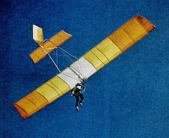
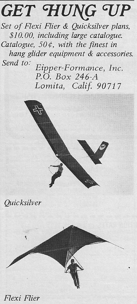
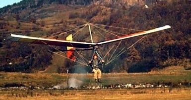
The popular Quicksilver monoplane hang glider was developed it into a very good power glider. With its twin-boom tail support structure, an engine mounted from the wing center section it offers gentle and forgiving flight characteristics and is generally foot-launched, though landing gear can be added.
Quicksilver B
The origin of the Quicksilver can be found in Bob Lovejoy’s High-Tailer design. The High-Tailer and early Quicksilvers all had a 4 foot chord and 30 ft span.
The original Quicksilver (later called the “A” model) was built from the High-Tailer. The twin verticals and high mounted horizontal were replaced with an “A” frame off the trailing edge of the wing, back to a fixed horizontal and a “C” frame rudder (no fixed fin). As the trailing edge of the “C” frame was unsupported, the rudder distorted a lot, but it was very effective at directional control, and the glider responded through dihedral effect (Cl-beta). The “C” frame rudder got replaced with a different “D” frame rudder which solved the distortion problem.
The Eipper guys thought to load test the Quicksilver and the failure occured at very low G, about 3.5 Gs, between the trailing edge flying wire and the center section. Also, the single upper wire to the tail didn’t provide much lateral support to the rudder loads. These led to the the first improved model of the Quicksilver, called the “B.” A wire was added from the control bar to the trailing edge of the wing (increasing the G limit to about 5.5), the “A” frame of the tail group gained a straight section between the horizontal and the rudder (making a square “U” section) and a second upper wire was added from the kingpost to the tail (one wire to each end of the squared-off “U”). The result was the best of the early model Quicksilvers, as a flying machine and structurally.
Dec 73 – Mar 74
The Quicksilver B, designed by Bob Lovejoy, was available as ready-to-fly, kit form, or as plans. The airframe is aircraft aluminium tubing, wings and tail surfaces are dacron covered. Pitch is weight-shift controlled, while the swingseats connected to the rudder controls turns.
A Quicksilver B kit in 1974 cost $545 and plans sold for $5. Ready to fly the Quicksilver B cost $965. A custom colour wing cost an additional $30.
There were homebuilt versions including one in 1974 with polyethylene covering instead of sail cloth.
Mark Clarkson, flying a Quicksilver in the spring of 1974, flew seventeen miles (measured as a straight line between take-off and landing). The farthest anyone had flown in a hang glider.
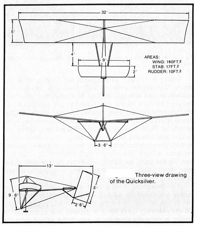
The next Quicksilver improvement was increasing the span (from 30 ft to 32 ft), increasing the chord (from 4 ft to 5 ft), and enlarging the tail (the rudder lost its characteristic “swept” leading edge). The wing also gained square tips (cf the “tapered” tip of the HT/QsA/QsB) to make the Quicksilver C model. This model also had a much reduced camber of the airfoil (the High-Tailer through Quicksilver B model had a “670-15” airfoil, which was made by bending a thin aluminum tube for one-half of it’s length over a 670-15 car tire; it was about 12% camber; the C and later models had about an 8% camber, again, IIRC). This was the same model that Jack Schroeder and Dave Cronk flew in the (much delayed) 1974 Nationals. The C model seemed to be the most prolific of the hang glider models.
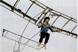
Cronk Quicksilver B
All HT and Qs models to this point had a tube for a trailing edge. An experiment was made of moving the trailing edge spar forward, and making a thin trailing edge of fabric only. The leading edge pocket was also made VERY large (maybe about 50% of the chord). Dave Cronk said it ruined the stall characteristics (very sharp and abrupt), but penetration went WAY up. This may have been called a “D” model. Later still the leading edge pocket was made even larger to enclose the leading and trailing edge spars (about 80%) making a double surface airfoil. This model was a rocket in Cronk’s hands, though it appears none were sold to customers.
Dave Cronk with a rudder connected to his harness via cords. Pitch is weight shift controlled.
First year motorized 1976.
Hang-glider. L/D: 7-1. Cruise: 18 25 mph. Gross wt: 395 lbs. Empty wt: 155 lbs. Max pilot wt: 220 lbs. Takeoff dist: 40-50 ft. ROC: 250 fpm.
Quicksilver B Wingspan: 30 ft Wing area: 116 sq.ft Weight: 56 lb Cruise speed: 22 mph Max speed: 32 mph Stall speed: 17 mph Max glide ratio: 7-1 Min sink: 250 fpm
Cronk Quicksilver B Wing area: 10.80 m² Wing span: 9.15 m Aspect ratio: 7.75 Hang glider weight: 25 kg Minimum speed: 35 km/h Maximum speed: 50 km/h Max glide ratio (L/H): 7 Minimum sink rate: 1.3 m/s
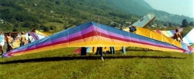
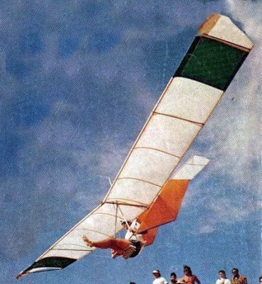
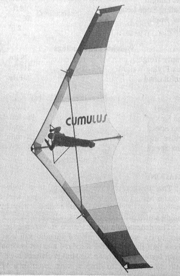
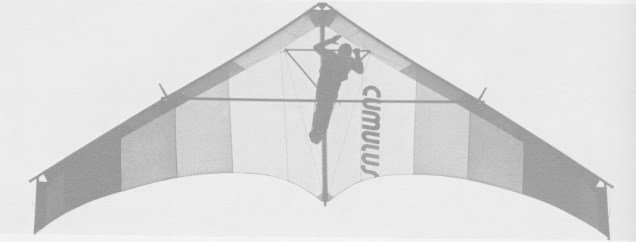
A 1977 high performance flexible wing. The Dave Cronk designed Cumulus has folding tubes for truncated wingtips. There are no battens, and the flying wires are adjustable for seated or prone.
The Cumulus V is a high-aspect ratio Rogallo hybrid with tip extensions, shaped keel and large, tapered, leading edge pockets. It is controlled solely by means of weight shifting. It is characterised by a higher wing loading and a faster cruise speed than for a standard Rogallo, giving it improved penetration. The stall is described as being gentle, with the nose dropping through at about 16 mph.
Take down and set up times should be within 10 minutes and the Cumulus V may be folded and transported like a standard Rogallo.
Cumulus V
The Cumulus 5B continues the development started in October 1974 and features a very lightweight frame, shaped keel, squared wing tips, and a roached sail with two battens per side. A fully battened sail was optinal. The light frame and small sail area gave fast and responsive control.
All aluminium components are fully anodised, and the triangle bar is adjustable to two positions for seated or prone flying. Spar saddles are brushed onto tubes for better distribution of loads, and tensioners are used on the top rigging, replacing turnbuckles. Wingpost blades are standard equipment, eliminating spar deflection.
Cumulus 5B
The Cumulus 5B airframe main tubes are 2044-T3 1.75in x .035 aluminium with the exception of the crossbar which is 6061-T6 1.75in x .049. All tbes are clear anodised, and all stress points are internally sleeved. Triangle bar is 6061-T6 1in x .083 black anodised aluminium.
Rigging cable is 3/32in vinyl coated stainless steel throughout. All ends are double nico pressed. Clip locking AN turnbuckles are used on the wingpost wires. All fittings are polished stainless steel and black anodised aluminium. Nuts and bolts are to AN specification.
The Haowe & Bainbridge 3.8oz stabilised dacron sail was available in 11 colours. A nine foot leading edge pocket was applied to eliminate bias stretching, all seams double zig-zag stitched, and all stress points heavily reinforced. Clear windows, special inserts, logos, air brushing, extra battens etc were available on request.
Seated harness and supine harness use individual leg straps and a wide back strap is used on both systems with the supine having fibreglass stiffeners added to aid comfort. The prone harness fully supports the pilot and is padded at all pressure points. It can also be flown for short periods in a seated position. Both systems use 5500 lb tested nylon webbing in load carrying positions.
Cumulus 5B painted by Mendij
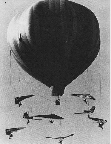
1975 world champion David Cronk organised a mass drop of eight Cumulus VB’s from a 320 ft high hot air balloon over California.
Cumulus V Wingspan: 29 ft 6 in Wing area: 165 sq.ft Aspect ratio: 5.2 Keel length: 12 ft Leading edge length: 18 ft Nose angle: 109 degrees Billow: 2.5 degrees Empty weight: 39 lb Max flying weight: 240 lb Useful load: 201 lb Best L/D: 7-1 Min sink: 250 fpm Stall speed: 16 mph Cruise: 25 mph
Cumules 5B 16 Leading edge: 16 ft Keel length: 9.5 ft Wing span: 26.1 ft Wing area: 136 sq,ft Aspect ratio: 5.0 Nose angle: 110˚ Sail billow: 2˚ Weight: 37 lb Pilot weight: 100-140 lb Takeoff speed: 12-15 mph Stall speed: 15-16 mph Max speed: 35 mph Best glide ratio (L/D): 7-1 Best L/D speed: 25 mph Min sink: 250 fpm
Cumules 5B 17 Leading edge: 17 ft Keel length: 9.5 ft Wing span: 28 ft Wing area: 145 sq,ft Aspect ratio: 5.4 Nose angle: 110˚ Sail billow: 2˚ Weight: 38 lb Pilot weight: 120-160 lb Takeoff speed: 12-15 mph Stall speed: 15-16 mph Max speed: 35 mph Best glide ratio (L/D): 7-1 Best L/D speed: 25 mph Min sink: 250 fpm
Cumules 5B 18 Leading edge: 18 ft Keel length: 10.5 ft Wing span: 29.5 ft Wing area: 165 sq,ft Aspect ratio: 5.3 Nose angle: 110˚ Sail billow: 2˚ Weight: 41 lb Pilot weight: 150-200 lb Takeoff speed: 12-15 mph Stall speed: 15-16 mph Max speed: 35 mph Best glide ratio (L/D): 7-1 Best L/D speed: 25 mph Min sink: 250 fpm
Cumulus 10 Wing span: 10.2 m Hang glider weight: 20 kg
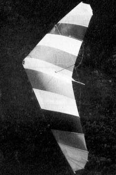
The Flexi 2 replaced the original Flexi Flier. It features fibreglass battens on each wing tip which allows wider tip chords, allowing a flatter sail cut while maintain docile slow speed and parachuting stall characteristics.
All aluminimum components are anodised, and the triangle bar is adjustable to two positions for seaed and prone flying. Spar saddles are bushed onto tubes for better distribution of loads, and tensioners are used on top rigging, replacing turnbuckles. Wingpost blades are standard equipment, eliminating spar deflection.
The 18ft, 20ft and 22ft Flexi 2’s use 1.5in, 1 5/8in and 1.75in .049in diameter tubing respectively. All tubing is clear anodised 6061-T6 aluminium. All stress points are reinforced with internal sleeving and all holes are bushed. The Triangle bar is 6061-T6 ix.083in black anodised aluminium.
The rigging is 3/32in 7×7 stainless steel wire rope throughout and is fully white vinyl coated. All ends are double nici pressed. Wire tensioners are used on the top rigging, while clip-locking AN turnbuckles are used n the wingpost wires.
All hardware is polished stainless steel and black anodised aluminium. Nuts and bolts are all to AN specifications.
The sail is Howe & Bainbridge 3.8ox stabilised dacron available in 11 colours. All seams are double zig-zag stiched and stress points are reinforced with 9oz cloth.
Seated harness and supne harness use individual leg straps and a wide back strap is used on both systems with supine having fibreglass stiffeners added for comfort. The prone harness fully supports the pilot and is padded at all pressure points. Both systems are 5500 lb test nylon webbing in load carrying positions.
The Flexi Flyer 3 was for Advanced pilots.
Flexi 2 18 Leading edge: 18 ft Keel length: 13 ft Wing span: 26 ft 6 in Wing area: 165 sq,ft Aspect ratio: 4.25 Nose angle: 95˚ Sail billow: 2.5˚ Weight: 37 lb Pilot weight: 110-50 lb Takeoff speed: 10-15 mph Stall speed: 10-14 mph Max speed: 35 mph Best glide ratio (L/D): 6:1 Best L/D speed: 23 mph Min sink: 290 fpm
Flexi 2 20 Leading edge: 20 ft Keel length: 14 ft 6 in Wing span: 29.6 ft Wing area: 205 sq,ft Aspect ratio: 4.25 Nose angle: 95˚ Sail billow: 2.5˚ Weight: 41 lb Pilot weight: 140-180 lb Takeoff speed: 10 mph Stall speed: 10-14 mph Max speed: 35 mph Best glide ratio (L/D): 6:1 Best L/D speed: 23 mph Min sink: 290 fpm
Flexi 2 22 Leading edge: 22 ft Keel length: 16 ft 6 in Wing span: 32 ft 6 in Wing area: 245 sq,ft Aspect ratio: 4.29 Nose angle: 95˚ Sail billow: 2.5˚ Weight: 46 lb Pilot weight: 170-220 lb Takeoff speed: 10-15 mph Stall speed: 10-14 mph Max speed: 35 mph Best glide ratio (L/D): 6:1 Best L/D speed: 23 mph Min sink: 290 fpm