
Michael A. Markowski built an experimental hang glider in 1971 as a canard stabilised kite. It made the stall more gentle and dive recovery automatic.
Michael A. Markowski built an experimental hang glider in 1971 as a canard stabilised kite. It made the stall more gentle and dive recovery automatic.

In the ski areas of New England, USA, Terry Sweeney of New Hampshire experimented with some Chanute typ. He and some friends made many flights, learned much and had fun. Their gliders replaced the older airfoils with more modern versions.
On the east coast, USA, in the summer of 1970, Robert G. Mixon of Miami, Florida, built and flew a Chanute-type biplane based on a plan found in a 1909 Popular Mechanics.
The local paper ran a front page headline “Those Magnificent Men In Their Flying Machine” on 15 June 1970. A local TV station even took some footage of a cliff launch. Mixon did it out of frustration due to the high cost of conventional flying.
Later, he offered plans, because of a large number of requests for his story which appeared in the February 1971 issue of Sport Aviation.

Richard Miller and his Conduit Condor was the highest performing hang glider at the first Universal Hang Glider Championships of 23 May 1971.
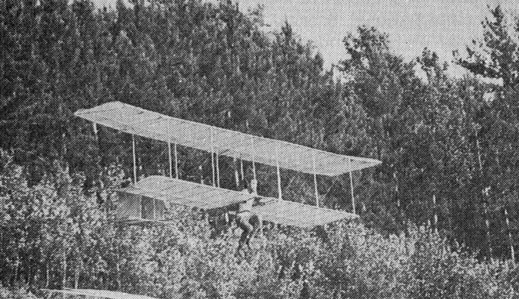
Pelzner was a builder of doppeldecker hangegleiter. In 1921 and 1922 he carried off many prizes. He built all his own craft and developed a simple structure that proved strong enough to carry him safely on flight after flight without serious mishap, yet light enough for him to control flight by bodily movements, changing the centre of gravity to trim the aircraft and overcome the upsetting effect of gusts or turbulence.
Pelzner’s gliders were astonishingly cheap despite financial trouble and inflation in Germany they cost him less than 20 marks to build. Derigged, they were small enough to be loaded onto a passenger train as traveller’s luggage at no extra charge; the parcel measured about 2.7m long, 1.3 m high, but only 50 cm thick.
The various Pelzner gliders differed a good deal in size and detail, although all were built roughly to the same basic scheme. The earlier models were built smaller and very light; 5.4 m span with total wing area of 14 sq.m. The weighed less than 10 kg. The later types spanned up to 7 m with areas of 16.5 sq.m, and weighed twice as much. Probably as Pelzner’s skill improved he was able to control bigger and more efficient gliders.
The framework was two tapered longerons, a shoulder width apart, running fore and aft with the lower wing main spars running cross wise and attached with bolts. At the rear these two main members were drawn together to support the tail unit, and from the tail to the upper end of the main wing struts two diagonal members ran. This basic framework was of oval or streamlined section timber, 2.5 cm by 4 cm in cross section where the loads were greatest, thinning down to 2 x 3 cm elsewhere. The upper and lower wings both had two spars, the front spars being 4 cm by 0.5 cm section, the rear spars 3.5 x 0.8 cm on the lower wing and 3.6 x 1.1 cm on the upper. Light curved ribs were bound to the spars, and the two wings were joined by light vertical struts, the outer ones being spindled I section to save weight. The whole structure was braced with wire.
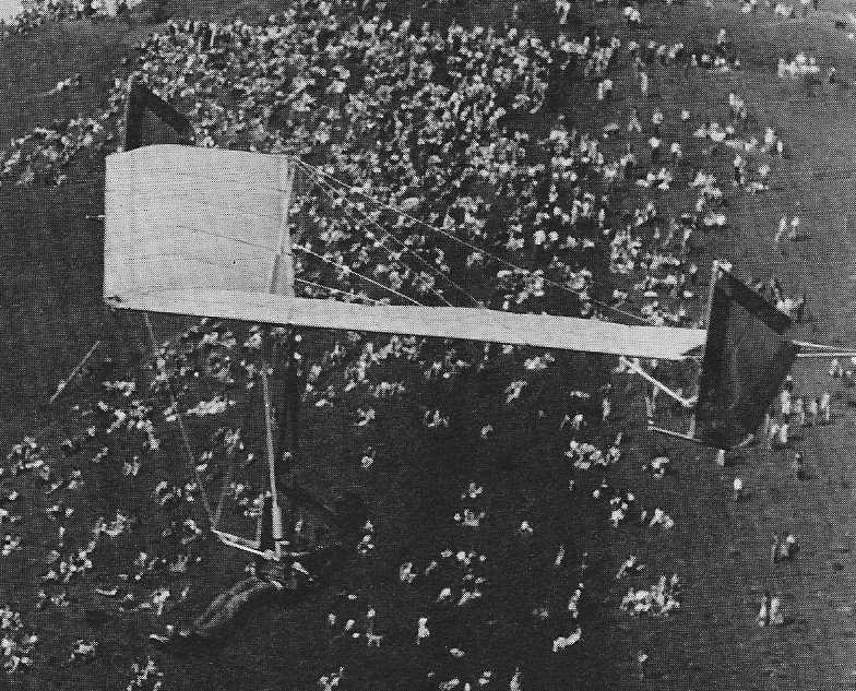
Pelzner covered his surfaces with oiled paper, glued onto the underside of the ribs of wing and tail. The leading edge of the lower wing was formed by the front spar, but the upper wing apparently had a light front member of wood or wire which gave a stiff entry to the primitive aerofoil. Some models had double thickness paper covering around the leading edge. The earliest models had no movable control surfaces at all, but later Pelzner fitted a rudder which he controlled by means of a sling around his right hand – a forward movement for a left turn, a backwards push for a right turn.
To manage these craft Pelzner worked out an athletic style of flying. At the 1921 meeting he accumulated a total flying time of 38 minutes, higher than any other pilot. He did this in a total of 62 flights aeraging over a half a minute each, some of them covering 400 and 500 m at his best glide ratio of about 6 to 1. In cash prizes he paid for his gliders hundreds of times over.
After monoplane glider flights the future was clearly not biplanes. Pelzner played little in the subsequent development of gliding.

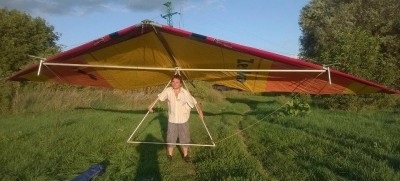
Breanewave hang glider
An early flying wing hang glider. The British Breanewave.

A 1979 hang glider.
A 1977 hang glider.

Minimum pilot weight: 73 kg
Maximum pilot weight: 86 kg
Minimum speed: 18 km/h
Maximum speed: 65 km/h

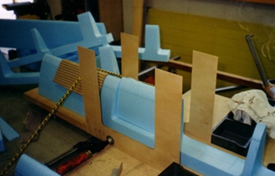
The Specter was designed during 1994-96, to build a glider that delivers much better performance than delta wings in fall and finesse rates, with good performance in the high-speed (up to 100 km / h) range.
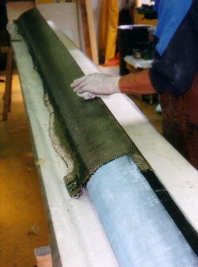
The D-tubes cover 20% of the profile. They were made of carbon / kevlar 200 gr / sq.m, directly on core of foamed 30kg / cu.m hollow, cut with hot wire. Unidirectional carbon beams have been inserted, as well as aluminum plates for riveting / screwing the various fixings: root, ribbed and cable ties.
The wingspan was set at 12.4 m, with a length of 12.4 m. The Worthmann FX 63-137 was designed to take advantage of take-off and low-speed behavior, and for the simplicity of the flaps. This profile has a maximum Cz of 1.7, and good stall characteristics. It equipped pedal-powered planes, but also motor-gliders. The wing tip of 3 degrees is obtained by modifying the back of the profile from half the wingspan of the wing.
To maintain the unique feel of the delta wing, as well as transport and simple assembly, the pilot is installed in a harness. Therefore, a trapezoid and the minimum of aerodynamic controls are required: only spoilers to turn, the rest will be done by displacement of the weight.

The trapeze will be used as an attachment to the lateral structural cables and will not be able, like on the rigid wings, to actuate the spoilers. Handles sliding on the speedbar will control them, using cords passing inside the uprights.
The ribs were also built with a foam-carbon / kevlar sandwich. They are connected to the D-tubes by aluminum fasteners, which also serve to fix the main cables for the median rib. Incident-maintaining cables are attached to the back of the rib by stainless steel fasteners. The ribs are extended with an aluminum tube for the tension of the sail.
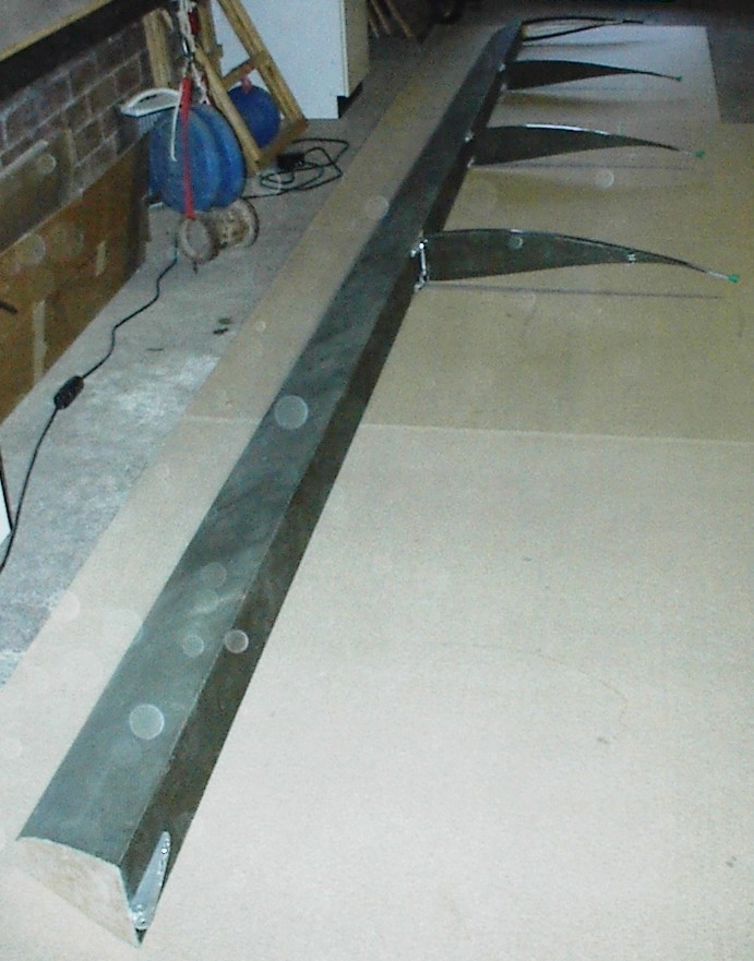
Sail work is dacron 160 gr / sq.m, more than 1km of polyester yarn. The empennage was manufactured in a very classic way, in wood covered with a heat-shrinking filament (Oracover). It is very solid and was a bit heavy: 3.6 kg. The drift consists of fabrics stretched over an aluminum frame and carbon.
The calculations (unfortunately inevitably somewhat imprecise) give a fineness of 18 to 48 km / h and a drop rate of 0.65 m / s to 40 km / h.
In 2002, the prototype was ready for its first tests.
There were various revisions, and the big flight came on October 12th. The rolling behavior was very pleasant, but there is too much stability in pitch.

Zahn renounced the formula of the flying wing, despite its great advantage in free flight: allow an easy takeoff. The formula, which subjects an aerodynamic element (the wing) to perform two distinct functions (ensuring the stability of the aircraft and lift with minimum drag) is a delicate compromise to design and calculate. It imposes profiles with little variation of moments, unsuitable for gliding, and an important twist which makes them work at unfavorable impacts at the tip of the wing.
Wing area: 12.4 m²
Wing span: 12.4 m
Wing profile: Worthmann FX 63-137
Tail surface: 1.5 m²
Hang glider weight: 45 kg
Minimum pilot weight: 60 kg
Maximum pilot weight: 80 kg
Minimum speed: 36 km/h
Maximum speed: 90 km/h
Max glide ratio (L/H): 18
Max glide ratio speed: 48 km/h
Minimum sink rate: 0.75 m/s
Packed length: 6.2 m
Nose angle: 180°
