1995-7: 4460 Shemwell Rd, Paducah, KY 42003, USA.
Farrington Aircraft produces the tandem two-seat Model 20A Heliplane cabin autogyro as a modern development of the Air & Space Model 18-A.
1998:
Route 3, Box 319
KY 42001 Paducah
USA
1995-7: 4460 Shemwell Rd, Paducah, KY 42003, USA.
Farrington Aircraft produces the tandem two-seat Model 20A Heliplane cabin autogyro as a modern development of the Air & Space Model 18-A.
1998:
Route 3, Box 319
KY 42001 Paducah
USA
With the concept of the convertible helicopter proved on a small scale with the Jet Gyrodyne, the proposal put forward by Dr. J.A.J. Bennett and Captain A.G. Forsyth in 1947 for a large compound helicopter looked viable, and various designs were considered.
The first mention of the project and of the name Rotodyne was made in March 1951 by the Ministry of Civil Aviation’s Interdepartmental Helicopter Committee in its initial report. No details were given, but it was reported to have two propeller-turbines and tip-jets, to have a cruising speed of 217km/h and capacity for 23 passengers. This was probably the Mamba-engined project.
Confirmation of the need for such an aircraft was provided by the British European Airways specification of December 1951 for a short/medium-haul ‘BEAline Bus’. Five manufacturers submitted projects to meet this earlier specification for a 30/40-passenger aircraft. Fairey’s original proposal again incorporated the projected D.H. powerplants. These were in two underwing nacelles, in each of which was located a main gas-turbine driving an auxiliary compressor and, mounted in tandem, a second turbine driving a constant-speed propeller through a reduction gear. Air for this turbine was tapped from the auxiliary compressor of the main engine. The rotor was four-bladed, with pressure-jet units at the tips.
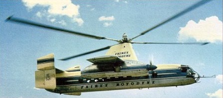
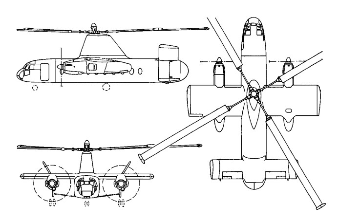
The Gyrodyne had rear clam-shell doors allowing the loading of large motor vehicles. A forward-located door permitted simultaneous entry and exit of passengers. The passenger compartment was 14m long, 2.4m wide, and 1.8m in height. The tail lower tail surfaces were oriented straight down, while the upper surfaces were canted at about a 45 degree angle.
The final version, with two Elands driving propellers and/or auxiliary compressors, was outlined in 1953 and formed the subject of a Ministry of Supply research contract. This became the definitive prototype, leading later, without very fundamental changes, to the proposed production Rotodyne FA-1, or Type Z, of 1959-60, with planned seating for up to 70 passengers. For this, XH249 (F.9430), the Elands could not provide the power required, so two 5,250shp Rolls-Royce Tyne propeller-turbines were envisaged. But in hot/high conditions, even this power would have been only just adequate in the engine-failure on take-off case, and Rolls-Royce suggested separate air-producing engines to supply the tip-jets.
The proposed solution was to install, at the rear of each nacelle, an RB.176 in which a lightweight gas-turbine drove an auxiliary compressor. By this use of separate propulsion and lift power there would be a considerable increase in weight, but the arrangement gave worthwhile gains in off-design conditions. The Fairey pressure-jet unit for the prototype consisted of a circular-section flame-tube fed by three air pipes and one fuel pipe. This was faired within a streamlined nacelle and terminated in a simple propulsive nozzle.
The BEA type specification for the production Rotodyne stipulated an initial climb, at zero forward speed and maximum weight, of not less than 1823m/min, and a noise level, at a distance of 183m, of not more than 96 decibels. With the power planned for the production Rotodyne the noise level for the existing tip-jets would have been about 113 db. To achieve the necessary 17-db reduction in noise level a complete redesign of the pressure-jet was planned. This would have been in two-dimensional form, occupying the last 1.2 metres of each blade, with nine circular flame-tubes in a combustion chamber submerged within the blade profile. Much work was done on silencers, but it was never reduced to the 96 decibels that the authorities demanded.
New test facilities were set up at White Waltham in 1951 for the development of the tip-jets. These consisted initially of a test stand and a rotating rig for chamber-spinning tests. A Rolls-Royce Dart engine, with air tapped from the combustion chambers, was used as a compressor plant for the rig; two other Dart compressor plants were used for the air supply to the rotating stand. On this, a balanced single-bladed rotor, with hingeless hub, was used to investigate tip-jet light-up, regulation, performance, cooling and loads during rotation. Prior to installation on the Jet Gyrodyne, a complete rotor, including hub, blades, jet units and controls, was installed. By the end of 1953 the chamber and rotor had been developed, and the Jet Gyrodyne flew untethered for the first time in January 1954.
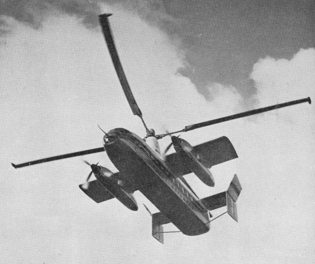
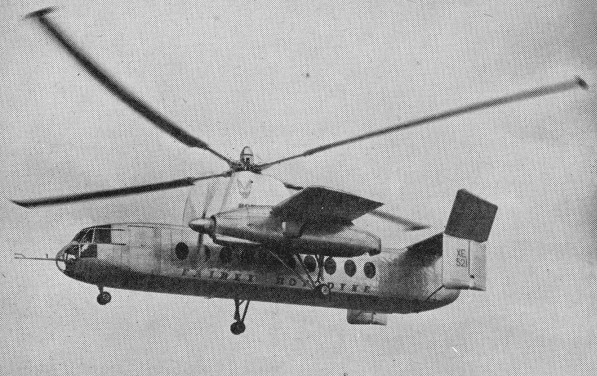
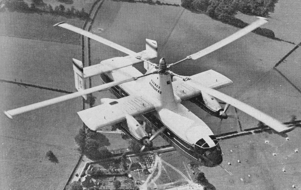
The Rotodyne was a square-section fuselage with untapered 14.17m stub wings on which were mounted two 3000shp Napier Eland turboprops for forward propulsion. The main wheels of the tricycle landing gear retracted forwards into the nacelles, and the nosewheel forwards below the cockpit. Twin fins and rudders, later joined by a central fin, were mounted on an untapered tailplane set on top of the rear fuselage. A large four-bladed rotor for vertical take-off and landing was driven by tip jets which received compressed air from the Eland engines via a compressor. To provide compressed air for the jets the two 2,800shp Napier Eland N.E1.7s operated as dual-purpose powerplants – acting either as normal propeller-turbines or as pressure-generators according to requirements. They were virtually normal Elands up to the rear of the turbine casing, where there was a nine-stage axial compressor driven by the power turbine through an hydraulic clutch. For take-off and landing most of the engine power was absorbed by the compressor, which delivered air to the internal duct system of the rotor. The small amount of remaining power of the engines went to the propellers for yaw control. In cruising flight all the power went to the propellers, with the rotor autorotating. Each engine fed air to two opposing blades so that, in the case of failure of one engine, there would be adequate pressure to keep two jets burning efficiently and giving maximum thrust.
All the earlier flying was completed with the fixed undercarriage while a revised form of retractable undercarriage, with special dampers, was designed and manufactured. This was fitted to the prototype soon after mid-year 1958 when the initial transition trials had been completed and the Rotodyne was being flown faster and for longer periods in the ‘winged autogyro’ mode.
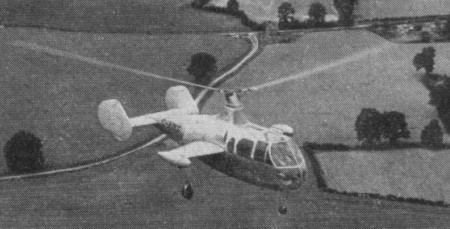
Following the resonance and running tests, the first untethered flight of the Rotodyne, XE521 (F.9429), was made by W. R. Gellatly and J. G. P. Morton at White Waltham on 6 November, 1957, and two further flights, carrying a flight observer, were made on the first day. Originally it had been intended to keep within the ground cushion during the early flights, but the prototype was taken on a circuit of the aerodrome, well above cushion height, on one of the first three flights which were made at a weight close to the 15,000kg maximum.
Until 10 April, 1958, all flights were made in the helicopter mode. On that day, at 1220m, the first transitions were made to and from the autogyro mode and thereafter a stage-by-stage transition technique was further evolved to ensure complete safety at all moments during the manoeuvres. During the 70 earlier helicopter flights, speed had been built up to 250km/h and altitude to 2072m before transition tests were started.

In its original form the control system followed that of the Jet Gyrodyne, with direct roll and fore-and-aft control through the cyclic pitch-change of the rotor-blades; with a trimming ‘elevator’ used to select fuselage attitude (and consequently wing lift) in cruising flight; and with yaw control by differential propeller-pitch at low speeds or when hovering, and by rudders at higher cruise speeds. Early in the test programme it was found that the fore-and-aft attitude control, using the separate functions of cyclic rotor-control and elevator trim, produced some difficulties. The solution was to link the elevator to the longitudinal cyclic control for both slow and high-speed flight and to disconnect the cyclic control when cruising.
Later, when it was found that the economical cruising speed was more like 273km/h than the originally planned 209km/h, it was found that, at higher speeds, the wing was doing too much work and the rotor too little, so that the blades were flapping and the control margins were inadequate. The wing, originally set at an incidence of 4°, was re-set at 0° and fitted with ailerons, the operation of which was linked directly to the cyclic lateral control of the rotor. The outward-sloping upper fins were also moved to the vertical so as to reduce the rolling tendency with yaw. These changes produced a normal ‘aeroplane-type’ rolling control for the pilot, and the situation was further improved later by the fitting of a third upper fin.
Towards the end of 1958 a decision was made to establish a speed record with the Rotodyne. The 100km closed-circuit category was considered to be the most usefully representative of the kind of operation for which the Rotodyne was designed and that in the new convertiplane class (E.2) was chosen. On 5 January, 1959, the Rotodyne was flown by Gellatly and Morton, with Dr D. B. Leason, Fairey powerplant flight observer, and E. J. Blackburn, strain-gauge operator, as ‘passengers’, over a measured circuit between White Waltham and Hungerford, Berkshire. The flight was completed at an average speed of 307km/h – which was 79km/h higher than the equivalent record for a helicopter and nearly 48km/h higher than that for absolute speed in a straight line. At that time the Rotodyne had not yet been modified with the reduced wing-incidence and the fitting of ailerons to improve control at higher speeds. The record, which was confirmed in March, stood until October 1961, when it was beaten by the Russian twin-rotor Kamov Ka-22 Vintokryl convertiplane.
On 16 June, 1959, the Rotodyne was taken outside the United Kingdom for the first time when it was flown to Paris for the 23rd Aeronautical Salon from London’s Heathrow Airport, via the Allee Verte heliport at Brussels and the Issy heliport in Paris before landing at Le Bourget. After demonstrations there, and at Versailles for officers of the North Atlantic Treaty Organization, the Rotodyne was flown back to Heathrow.
During 1959 the wings were given ailerons and increased incidence, and the vertical tail surfaces were also revised. On 7 February 1960, XE521 resumed trials with an added central fin, shortened exhausts and a fully-faired rotor pylon.
Budgetary problems of the time saw the RAF and British Army withdraw their interest and the Rotodyne became a wholly civil project.
During 1958 the Kaman Aircraft Corporation secured a licensing agreement for sales and service in the USA with a possibility of manufacture there. Okanagan Helicopters of Vancouver was interested in three and Japan Air Lines was considering the type for domestic routes. However, the biggest potential customer was New York Airways, which joined with Kaman in a letter of intent for five, plus options on 10, for delivery in 1964.
The provisional order from NYA was for the bigger-capacity, 54/65-seat Rotodyne powered with Rolls-Royce Tyne propeller-turbines and with a gross weight of 22680kg. There had been earlier references to the use of Tynes in the production version, but this order led to the first fuller statements about this version, for the development of which an additional GBP8-10 million was needed. The Government had offered to contribute half this sum, up to a certain fixed maximum, with repayment through a sales levy, but this was conditional on a firm order from BEA. Confirmation of the NYA order depended on several factors — including one that the first ‘Mk.2’ Rotodyne should be flying on test by the autumn of 1961 and another that the noise-level should be acceptable to the airline and airport authorities.
At the Paris Salon in June 1959 a model of the production version had been exhibited in the markings of New York Airways.
Fairey needed up to GBP 10 million to develop this version and was offered 50% of this by the government if BEA would place a firm order. The government contribution was to be a loan, repayable by a sales levy. In 1960 Fairey merged with Westland and although initially the Rotodyne project looked secure, it was not. In April 1960 Okanagan cancelled its order because of the long delivery dates, and five months later New York Airways expressed concern over the delay in production plans. Westland was then involved in taking over Bristol’s helicopter programme as well as with other work in hand. This, together with the ever-increasing weight of the Rotodyne, which reached a stage where the Eland could no longer be developed and the Tyne could not be afforded, led to withdrawal of government support, and the project was cancelled on 26 February 1962. On that date the British Minister of Aviation, Mr Peter Thorneycroft, said that, because of the costs involved, it was necessary to ‘forego the operational advantages’ offered by the military version, and that British European Airways, then its only potential British civil operator, had regretfully concluded that ‘the commercial prospects on their routes were not sufficiently assured to justify the heavy liabilities involved’ in placing a production order. In the absence of any firm order, Westland Aircraft did not feel justified in proceeding with the project.
GBP11 million was spent during the nine years or so following the placing of the original research contract in July 1953. During the final three years of the period, however, financial support had been uncertain and the project suffered from continuing political and other indecisions which made costly forward planning impossible.
The Rotodyne was subjected to a vigorous flight test program of over 350 flights, more than half of them demonstrating 200 hover-to-vertical flight transitions.
Engines: 2 x Napier Eland NE1.7 turboshaft, 2088kW
Main rotor diameter: 27.4m
Wingspan: 14.17m
Fuselage length: 17.88m
Height: 6.76m
Internal cabin length: 14.02m
Loaded weight: 14969kg
Cruising speed: 298km/h
Max range: 724km
Cabin volume: 93cu.m

In preparation for the move into rotary-wing development, Fairey had built up a strong helicopter team, led by Dr J. A. J. Bennett, who brought the Gyrodyne proposal to the company in August 1945, and with Sqn Ldr Basil H. Arkell, who joined in January 1946, as test pilot. The first official announcement of the project, a private-venture to specification E.4/46, was made on 3 April, 1946, though no information was then given; at that time the Gyrodyne was known as the FB-1 (Fairey-Bennett One).
Although the broad concept was relatively simple, the translation of this concept into working hardware involved a considerable effort in engineering and other ingenuities. An idea of the amount of ‘machinery’ in the prototype can be gathered from the fact that nearly 50 per cent of the empty weight was contributed by the powerplant and transmission systems. In these there were four primary units: a 520hp Alvis Leonides nine-cylinder radial engine, with its mounting and systems; a main gearbox with first-stage reduction for the rotor and propeller drives, a clutch and freewheel; an upper gearbox with double epicyclic reduction gear, plus the rotor brake; and a gearbox in the starboard wingtip with the reduction-gear and pitch-changing mechanism for the propeller.
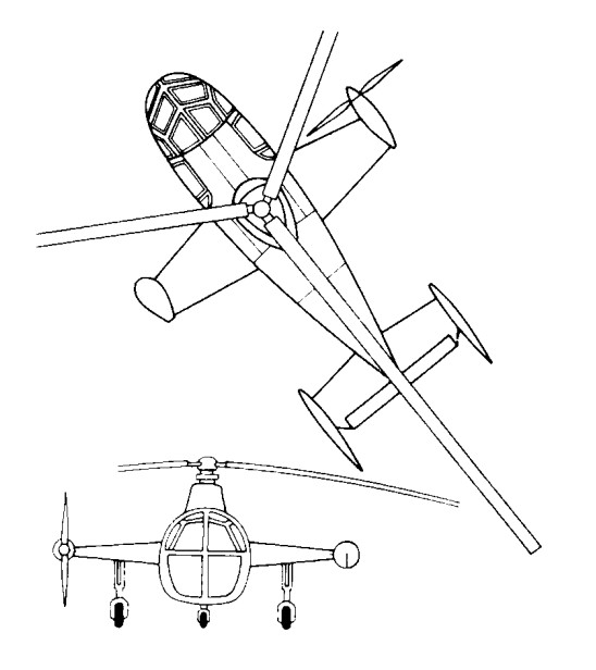
The engine power could be transmitted in variable ratios to a three-blade rotor just over 15m in diameter and to the anti-torque propeller on the starboard tip of the stub wing, the Gyrodyne behaved like a helicopter, but the same propeller also provided the necessary thrust for fast flight, when the aircraft looked almost like an autogyro.
The rotor articulation was designed so that the collective-pitch changed automatically according to the power being applied. The throttle lever was designed to be similar in length, movement and effect to the collective-pitch control of a conventional helicopter and was pulled up to increase power and lift. Fore-and-aft and lateral control was provided by a form of tilting head; although the rotor-hub axis did not physically tilt, as in the case of most autogyros, a similar effect was produced by tilting the rotor head in relation to the axis. Stick-shake was eliminated, using suitable safeguards, by controlling rotor-tilt through irreversible hydraulic jacks.
The Ministry of Supply asked for an alternative rotor-hub arrangement to be designed with overriding collective-pitch and cyclic-pitch blade-angle control so that this could be compared on test with the existing system. This normal helicopter control system was required mainly for trimming purposes at altitude and to provide more positive control when hovering after an autorotative approach.
Yaw control was maintained, as with other helicopters, by altering the pitch of the propeller through conventional pedals. Rudders were fitted for directional control during autorotative flight after power failure. An ‘elevator’ in the form of a large trim tab, was used to adjust the fuselage attitude when cruising.
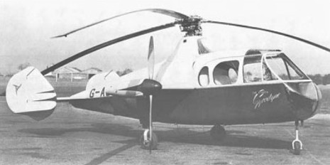
A government contract to Specification E.4/46 was awarded for two prototypes, and the first Fairey Gyrodyne, G-AIKF (provisionally serialled VX591), was exhibited almost complete at White Waltham on 7 December 1946.
After 85 engine-running and 56 rotor-testing hours the first untethered flight was made at White Waltham by Basil Arkell on 7 December 1947, weighing just over 2000kg. Testing continued, with longer flights at gradually increasing speeds, until March 1948, when the Gyrodyne was dismantled for examination. By then a second prototype, G-AJJP, had been completed.
The second prototype, basically similar to the first but with more comfortable interior furnishings befitting its role as a passenger demonstrator, was flying by the time of the next SBAC Display, in September 1948, at Farnborough.
Following re-assembly and further tests, G-AIKF was prepared for an attempt on the international helicopter (Class G) speed record in a straight line. This had long been held unofficially by the German Focke Achgelis Fa 61 and more recently a Sikorsky R-5 had also been unofficially timed at 185km/h in the USA. Two eastward and two westward flights over a 3km course at White Waltham were made by Arkell on 28 June, 1948, at an average speed, for the best pair of opposing runs, of 200km/h. In addition to being a world record, this was the first British national record for any helicopter. The course was along the London-Reading railway line on the north side of the aerodrome, and, as it happened, was 45 degrees off a fairly strong wind, so the probability is that a speed of 225km/h might have been achieved in calmer conditions.
Some ten months later an attempt to set up a 100km closed-circuit record ended in tragedy. During trials on 17 April, 1949, two days before the attempt was to be made, the first prototype Gyrodyne suffered a fatigue failure in the rotor head and crashed at Ufton, near Reading, killing F. H. Dixon and his flight observer, Derek Garroway. Dixon, who joined Fairey in 1936 and was chief test pilot from 1942 to 1945, had since been involved in less arduous flying and other duties, but had also shared much of the development and demonstration flying of the Gyrodyne with Basil Arkell.
The investigation following the accident led to a protracted period of investigation and fatigue-testing, and development ceased. The second prototype was grounded and was afterwards very much modified to reappear more than four years later as the Jet Gyrodyne, the test vehicle for the Rotodyne.

Engine: 1 x Alvis Leonides, 388kW
Main rotor diameter: 15.77m
Fuselage length: 7.62m
Height: 3.10m
Take-off weight: 2177kg
Empty weight: 1633kg
Max speed: 124 mph
Seats: 4-5
Founded by C R. (later Sir Richard) Fairey, initially to build 12 Short 827 seaplanes. Leased premises at Hayes, Middlesex, replaced by new factory 1917-1918. Became a public company March 5,1929 and the following year opened new airfield at Harmondsworth, later requisitioned and incorporated in site for London’s Heathrow Airport. Reorganized as holding company The Fairey Company Ltd. March 31,1959, aircraft manufacturing subsidiary becoming Fairey Aviation Ltd. and the Stockport plant Fairey Engineering Ltd. Fairey Aviation Ltd. merged with Westland Aircraft Ltd. in 1960. Britten-Norman (Bembridge) Ltd. acquired 1972. Fairey group into liquidation 1977; engineering activities acquired by National Enterprise Board; Britten-Norman operated by liquidator pending sale.
Company designs included F.2 twin-engined biplane fighter; camber-changing trailing-edge flaps introduced on Hamble Baby. Fairey III series introduced 1917; final model IIIF entered production 1926 and declared obsolete 1940. Fairey Hendon (1930) was the first British cantilever monoplane heavy bomber; Long-range Monoplane captured absolute distance record for Britain 1933. The famous Fairey Swordfish (“Stringbag”) torpedo bomber entered production in 1936; 2,392 were built by Fairey and Blackburn; it was the only biplane to remain in service throughout Second World War. Other famous aircraft included Battle light bomber, Fulmar fleet fighter, and Barracuda dive-bomber. Firefly name revived for Rolls-Royce Griffon-powered monoplane which entered FAA service in 1943, serving in Korea in 1950. First FAA aircraft to combine search and strike roles was the Gannet with Double Mamba coupled turbines; developed Gyrodyne convertible helicopter 1946; Jet Gyrodyne 1953; Rotodyne compound helicopter airliner 1957. Fairey Delta 2 research aircraft set world air speed record of 1,822km/h on March 10, 1956.

Britten-Norman became Fairey Britten-Norman in 1974.
Faiery Aviation joined Westland in 1961.
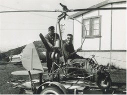
The Everson gyrocopter was built by Ron and Ernie Everson in the early 1960s. The gyrocopter was tested at Muriwai Beach, New Zealand, where it was tethered to a vehicle and driven at high speed. The aircraft did not receive a Certificate of Airworthiness.
Ron Everson donated the gyrocopter to MOTAT in 1982.
New Zealand
The brothers were passionate about aviation for many decades around the 1960s.
A single seat partially enclosed autogyro, first flown 1984 and sold in assembled form. Built of bolted-together square aluminium tube. Stream lined body enclosure, wheel pants, molded fuel tank mounted low behind seat.
Engine: Rotax 582/532.
Prop: 52” GSC or similiar.
Rotor blades: 22’ Dragon Wings.
Min speed: 10 mph.
Cruise: 70 mph.
Top speed: 100 mph.
Empty wt: 410 lbs.
Useful load: 440 lbs.
Gross wt: 850 lbs.
Width: 6’6”.
Height: 8’4”.
Length: 10’.
R.J. Everett Engineering Ltd.
Developed a single-seat autogyro, first flown 1984 and sold in assembled form.
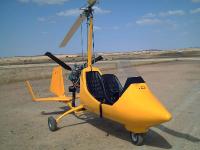
The main frame is made with stainless steel tubes and sheets cut with CNC laser machinery and welded by aeronautic welding in a TIG atmosphere. The main frame is designed and tested to support 5 Gs loads with maximum weight at takeoff. The rotor control system is duplicated to be able to pilot from both seats. Like the frame, it is made of stainless steel.
All of the gyro points are mounted on stainless steel ball bearings with ZZ protection. The two joysticks consist of a “top gun” type stick with rotor trim controls and radio button (ptt) controls.
The rotor head consists of parts tooled with a CNC machine. The parts are made of stainless steel, high strength steel and 7075 T6 hard aluminium. The bolts used are ISO certified.
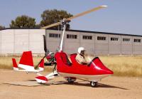
The autogyro’s cabin is manufactured in carbon fibre and epoxy resin composite materials.
The 08 model’s cabin is equipped with two windscreens. The tail unit is manufactured in carbon fibre and epoxy resin. The tail unit’s frame design has been tested to the limit by Spain’s Civil Aviation Department and has shown its strength at speeds of up to 210 Km/hr.
The ELA rotor is manufactured in a combination of aluminium and fibreglass with epoxy resin. The blade can support traction loads of up to 26,000 Kg, whereas the top flight load does not exceed 6,500 Kg.
Standard Equipment for ELA 08 includes altímeter, airspeed, vertical speed, compass, engine and rotor rpm, cht, oil temperature, oil pressure, fuel pressure, trim position indicator, hour counter, “top gun” stick in front and back positions, mechanical prerotator, pneumatic rotor brake with parking system, pneumatic trim, back compartment glove box, wheel spats, landing light, 72 litre fuel tank, carbon fibre propeller, aluminium and carbon fibre rotor blades, carbon fibre cockpit, wheel spats and tail plane, front wheel cover, and stone guard.
Optional extras include egt, strobe light, manifold pressure, propeller spinner painted, rear instrumental panel with airspeed indicator, engine rpm, rotor rpm, altimeter, and fuel pressure.
R-100
Engine; ROTAX 912 UL
Empty weight; 237 kg
Maximum Take-off Weight; 550 kg
Total Payload; 306 kg
Range; 500 km
Min Speed at Level Flight; 30 km/h
Cruise Speed; 140 km/h
Take Off Distance – 1 person; 30 m
Take Off Distance – 2 persons; 80 m
Rate of Climb – 1 person; 7 m/s
Rate of Climb – 2 persons; 5 m/s
R-115
Engine; ROTAX 914 UL
Empty weight; 244 kg
Maximum Take-off Weight; 550 kg
Total Payload; 306 kg
Range; 500 km
Min Speed at Level Flight; 30 km/h
Cruise Speed; 150 km/h
Take Off Distance – 1 person; 20 m
Take Off Distance – 2 persons; 50 m
Rate of Climb – 1 person; >10 m/s
Rate of Climb – 2 persons; 8 m/s
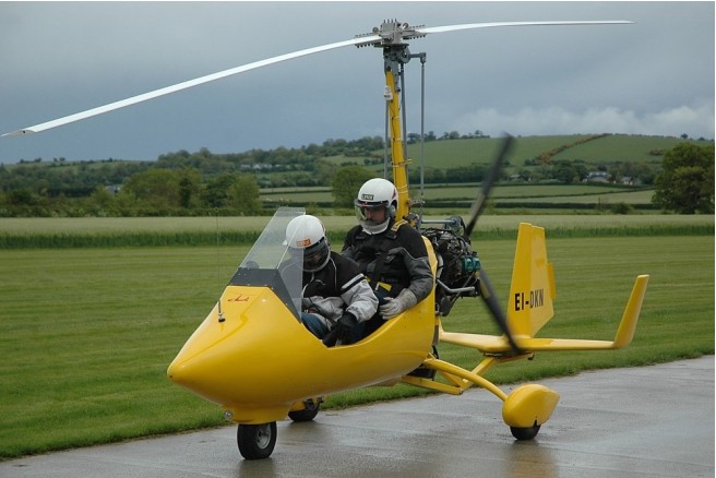
The main frame is made with stainless steel tubes and sheets cut with CNC laser machinery and welded by aeronautic welding in a TIG atmosphere. The main frame is designed and tested to support 5 Gs loads with maximum weight at takeoff. The rotor control system is dual to be able to pilot from both seats. Like the frame, it is made of stainless steel.
All of the gyro points are mounted on stainless steel ball bearings with ZZ protection. The two joysticks consist of a “top gun” type stick with rotor trim controls and radio button (ptt) controls.
The rotor head consists of parts tooled with a CNC machine. The parts are made of stainless steel, high strength steel and 7075 T6 hard aluminium. The bolts used are ISO certified, which guarantees their reliability and standardization. The rotor head houses the advanced pre-rotator and trim systems that are characteristic features of our autogyro.
The autogyro’s cabin is manufactured in carbon fibre and epoxy resin using state-of-the-art techniques for composite materials. Our plant has the right facilities for using advanced techniques, including air-conditioned cabins, curing furnaces and humidity control systems.
The 07 model’s cabin is equipped with a windscreen to protect the front seat.
The tail unit is manufactured in carbon fibre and epoxy resin. The tail unit’s frame design has been tested to the limit by Spain’s Civil Aviation Department and has shown its strength at speeds of up to 210 Km/hr.
The ELA rotor is manufactured in a combination of aluminium and fibreglass with epoxy resin. The rotor blades are manufactured yjr ELA plant and which has been certified by the Spanish Civil Aviation Department. The certification tests have proved that the blade can support traction loads of up to 26,000 Kg, whereas the top flight load does not exceed 6,500 Kg.
Standard equipment for the ELA 07 includes altímeter, airspeed, vertical speed, compass, engine and rotor rpm, cht, oil temperature, oil pressure, fuel pressure, trim position indicator, fuel level, hour counter, mechanical prerotator, pneumatic rotor brake with parking system, pneumatic trim, landing light, 72 liters fuel tank, carbon fibre propeller, carbon fibre cockpit and tail planes, aluminium and carbon fibre rotor blades, front wheel cover
stone guard . Optional extras include EGT, wheel spats, strobe light, manifold pressure, and dual controls.
Engine; ROTAX 912 ULS
Empty weight; 237 kg
Max Take-off Weight; 550 kg
Total Payload; 313 kg
Range; 500 km
Min Speed at Level Flight; 30 km/h
Cruise Speed; 140 km/h
Rate of Climb; 5-7 m/s
Take Off Distance; 30-80 m
