Groen Hawk 4 / Jet Hawk 4T

Design changes to H2X and later Hawk III in October 1998 resulted in Hawk 4. Initial aircraft (N402GB) first flew 29 September 1999, powered by a Continental piston engine, and made first vertical take-off on 9 December 1999; had flown 120 hours in 200 sorties by early April 2000. In September 2000 company switched certification effort to turbine-powered Hawk 4T (N403GB), which was renamed Hawk 4 at this time following abandonment of piston-engined version; the following October Groen changed its focus to seek government contracts for Hawk 4, slowing certification process for both piston- and turbine-powered versions until it sees market upturn.
GBA analysises and optimises gyroplane rotor blade airfoil performance resulting in a family of natural laminar-flow airfoils for the rotor blades of the Hawk 4 and successor gyroplanes. The airfoil design optimizes the lift/drag relationship for the Hawk rotor system. Initial Hawk models will use aluminum rotor blades with GBA’s proprietary airfoil design, and subsequent models are anticipated to use composite blades with an enhanced GBA proprietary airfoil design that will permit increased operating speeds.
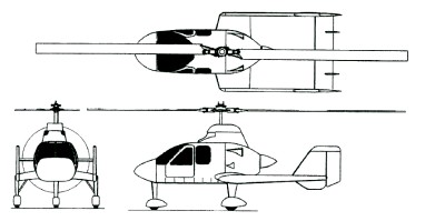
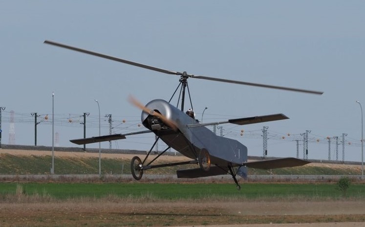
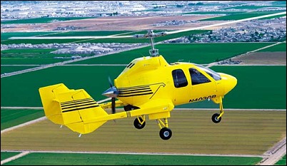
The aircraft features twin tailbooms supported by stub-wings which also house main landing gear, and twin stabilisers and rudders with fixed horizontal tail surface mounted between the vertical tails. A two-blade, semi-rigid aluminium teetering rotor with swashplate has a rotor speed of 270rpm. The collective pitch-controlled rotor head allows vertical take-off (zero ground roll) and enhanced flight performance. Rotor brake is standard. Actuation by pushrods. Patented dual-control stack cyclic flight controls.
The structure had a steel mast and engine mounts; stressed skin aluminium semi-monocoque fuselage, tail unit, hub structure and propeller; composites nose, engine cowling and wingtips; acrylic windscreen and doors; glass fibre nosecone and engine cowling.
The undercarriage is fixed tricycle type with mainwheel tyres 6.00×6; nosewheel 5.00×5, Cleveland hydraulic brakes, and twin safety wheels at rear of tailbooms.
Hawk 4 piston-powered version has air-cooled, six-cylinder Teledyne Continental TSIO-550 rated at 261kW at 2.700rpm; prototype had four-blade MTV propeller but production models will have Hartzell three-blade constant-speed propeller. Engine provides power to rotor for prerotation to provide for short and vertical take-off capability; power to rotor system never engaged during flight.
Fuel capacity is 284 litres in a single tank at the rear of the fuselage and a refuelling point at the top of the fuselage. Oil capacity 11.4 litres.
The pilot and up to three passengers are in an enclosed cabin in two pairs of seats. The rear seats folding to provide baggage space.
The electrical system is 28V DC.

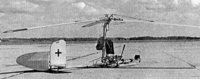
The production prototype for Hawk series was powered by a 134kW Textron Lycoming O-360-A4M flat-four.
The company has a flight test facility at Buckeye, Arizona, where, on 12 July 2000, the prototype Jet Hawk 4T / Hawk 4 made its initial flight. This turbine-engine version is powered by a Rolls-Royce Model 250 420shp turboprop engine driving a three-blade constant-speed propeller, first flown (N403GB) on 12 July 2000. Other changes include addition of underfins and taller landing gear. Two further prototypes under construction.
The Hawk 4T is sold fully assembled with a Rolls-Royce Model 250 B17C gas turbine for $749,000 in 2001. By May 2003, deposits on 148 aircraft had been taken, via 12 dealerships at around US$749.000 (2003). Fractional ownership programme announced July 2001 but later dropped.
The Hawk 4 was an integral part of security during the 2002 Winter Olympic and Paralympic Games. On 28 December 2001, Groen announced contract with Utah Olympic Public Safety Command for lease of Hawk 4, beginning 20 January 2002, for security patrols at Salt Lake International Airport, equipped with video downlink system, Spectrolab SX-5 searchlight and additional radios. The Hawk 4, during its operational period for the Utah Olympic Public Safety Command (UOPSC), was available 24-7, completed 67 missions and accumulated 75 hours of maintenance free flight time.

Hawk H4
Engine: Rolls-Royce 250, 420shp
Rotor diameter: 12.80m
Fuselage length: 7.31m
Overall height: 4.11m
Empty weight: 835kg
Max. take-off weight: 1587kg
Useful load: 960 lb
Fuel capacity: 75 USgal
Max. speed: 238km/h
Cruising speed at 75% power: 212km/h
Max. rate of climb at sea level: 457m/min
Service seiling: 4875m
Take-off run: 8m
Range with max fuel at 75% power: 584km

Groen Proof-of-concept / Hawk 1 / H2X / Hawk III

flew several prototype test gyroplanes of increasing size and sophistication during the 1990s.
Based on proof-of-concept Hawk One (N4379X) first flown 26 September 1992; design started April 1996 and prototype two-seat H2X (N4412X) first flew 4 February 1997. The H2X was later converted to three-seat Hawk III standard. The Hawk III multipurpose cabin gyroplane was capable of vertical (jump) take-off. First deliveries had been due June 1998, but design changes to H2X and later Hawk III in October 1998 resulted in Hawk 4.

Hawk H2X
Engine: one 335kW Geschwinder V-8 aluminium liquid-cooled engine, derated to 261kW at 2.500rpm
Propeller: Hartzell three-blade constant-speed.

Groen Brothers Aviation

Salt Lake City, Utah, USA

GBA was founded in 1986 by David Groen and his brother, Jay Groen. GBA’s Corporate Headquarters are located in Salt Lake City, Utah, USA, with its manufacturing facility on the same site. GBA also operates a flight test and R&D facility in Buckeye, Arizona, near Phoenix.
Since its inception, GBA has been involved in an extensive research program in the design, engineering, development, testing and marketing of gyroplane and gyrodyne aircraft.
Groen Brothers Aviation, Inc. (GBA) is engaged in the business of designing and developing new high performance gyroplanes and gyrodynes using advanced technology and modern aerospace design methods.
The Groen brothers realized that the collective pitch controlled rotor system developed for helicopters could be applied to a gyroplane. This innovation would substantially improve a gyroplane’s ability to achieve vertical takeoff and landing, as well as dramatically improve performance in both high speed flight and safe low and slow flight. GBA has three U.S. Patents and several International Patents relating to the variable pitch rotor system they developed. With such improvements the gyroplane could become a safe, economical and versatile aircraft with appeal to a broad range of markets. Based on this insight, the Groens decided in 1986 to enter the market and to design their first gyroplane.
Following the successful flight of a proof-of-concept aircraft in 1987, the Groens designed, manufactured and flew several prototype test gyroplanes of increasing size and sophistication during the 1990s. Each of these gyroplanes were typically ultra-short take-off and landing (USTOL) aircraft that demonstrated that gyroplanes could be significantly easier to fly and maintain than a helicopter, would have significantly less maintenance down time and therefore much higher mission readiness, and would be safer than either airplanes or helicopters.
By 1999 Groen Brothers Aviation had designed and manufactured their first piston-engine version of the four-seat Hawk 4 Gyroplane.
In July 2001, Groen announced plans to move to a new 18.580sq.m facility at Phoenix, Arizona. The plant was intended to become operational by end 2002 and have the capacity to produce four aircraft per day, however this has lapsed.
In August 2001 the company concluded a joint venture with Al-Obayya Corporation to produce and market gyroplanes in Saudi Arabia. However, economic downturn of late 2001 resulted in 85 of 130-strong workforce being laid off. Earlier plans for Chinese assembly also appear to have lapsed.
In February, 2003, Groen Brothers Aviation formed American Autogyro, to produce gyroplanes for the “kit-built” market.

Getafe Ultralight Club Cierva C.4

The project is the result of a decision by a group of friends at the Getafe Ultralight Club to commemorate the centenary of Juan de la Cierva’s historic first flight in his C.4 during January 1923. Following more than a thousand hours of design and fabrication work, the replica C.4 was ready for its official unveiling in January at Getafe Air Base, not far from the very spot where the original had first taken flight a hundred years earlier. The public unveiling took place at Camarenilla aerodrome March 2013, but the team chose to move the aircraft to Ocaña for its first flight. They disassembled the replica C.4 in the morning, driving it to the historic Ocaña Aerodrome by truck and then reassembling it.

Initial ground tests without the (unpowered) main rotor fitted, were carried out to check the engine operation and to test the aircraft in high-speed taxiing. After the crew fitted the rotor, a test run took place just a little after 6:00 p.m. local time. Pilot Fernando Roselló began the taxi run – but the autogiro lifted off briefly and then landed gently.

After this small jump, other takeoffs followed, until, finally, the Cierva took off and completed a couple of full circuits. Nerves, illusion and adrenaline were rewarded by seeing the autogyro take off from the ground without incident and land again successfully.

This particular early model does not having direct control through the inclination of the rotor hub, but rather still retains roll and elevator control with ailerons and rudder. While the replica C.4 stays true to much of the original design concept, the replica team chose to include some safety concessions, such as a modern engine and a well-proven, two-bladed rotor design (in place of the original four-bladed system which had only a marginal useful life of just a few hours flight time). One of the team engineers added that the rotor system, as it is without direct control, is based on Cierva’s patent, number 100595 of Dec 1926.

After alighting, Fernando Roselló stated that the aircraft behaved just as he had expected. It is a very stable aircraft, but since it lacks direct control (using aerodynamic control instead) it is slower to respond to control input. He flew as slowly as 50km/h and estimated a cruise of about 80km/h at about 4,500rpm, comparing it to 4,700rpm on his 80HP Rotax powered 912 gyroplane which flew at 80km/h with a positive variometer (rate of climb indicator).

Frazer-Walker Gyrojet

Reported in 1964, the Frazer-Walker Gyrojet four-place VTOL amphibian to be built by Handley Page Ltd, London, sold in the US by Frazer-Walker Aircraft Corp, New York, has a 250hp Lycoming engine mounted aft driving a two-bladed pusher propeller. Lift is from a three-blade rotor fitted with mechanical “spin-up” device for short takeoff and a tip-jet powered system for use when a vertical takeoff is desired. The fuselage is of fibreglass. Royor blades are uncoupled from the engine in flight and rotate under aerodynamic forces.

Engine: 250hp Lycoming
Useful load: 1070 lb
Gross weight: 3000 lb
Top speed: 145 mph
Range: 750 mi

Focke-Achgelis Fa-330 Bachsteize

Early in 1942, Focke Achgelis at Laupheim were asked to design a simple single-seat gyro kite which surfaced U-boats could tow aloft to extend the observer’s range of view. At this time, the U-boats were being forced away from the dense shipping areas around the coasts of Britain and the United States to hunt further out into the Atlantic where there was greater safety, but where their low position in the water made searching for, and shadowing, the spread-out convoys a very difficult task.

The gyro kite, designated Fa 330 Bachstelze, was seen as of solution. The machine could be easily assembled or dismantled in a few minutes and stowed through a U-boat hatch. The body structure consisted of two main steel tubes, one horizontal and one vertical. On the horizontal tube was mounted the pilot’s seat with controls and a small instrument panel, and landing skids, and, at the rear end, a simple tailplane, fin and rudder. The vertical tube, behind the pilot’s seat, formed a pylon for the rotor.

The freely-rotating rotor had three blades, each of which consisted of a tubular-steel spar with plywood ribs and thin plywood and fabric covering. Each rotor blade had flapping and dragging hinges with adjustable dampers. Blade pitch could only be adjusted, with screws, on the ground before take-off. The best results were normally obtained with the blade pitch as coarse as possible, although starting was then more difficult. In addition to the flapping and dragging dampers, there were also inter blade connecting cables and blade-droop cables, the latter being attached to the blades and to an inverted tripod extending upward from the rotor hub. The rotor axis was slightly ahead of the machine’s c of G, and the towing cable attachment point was slightly ahead and below the c of G.

Movement of the control column tilted the rotor head in the appropriate direction for longitudinal and lateral control, and operation of the rudder pedals gave directional control. The tailplane was not adjustable. The Fa 330 was launched from the deck of the surface-running U-boat by giving the machine a slight backwards tilt once the rotor was revolving. If there was a wind, a push by hand sufficed to get the rotor moving, but otherwise a pull-rope was wound around a grooved drum on the rotor hub. In case this rope did not slip off when the rotor started, an over-ride mechanism was fitted.

Pilot training was given in a wind-tunnel at Chalais-Meudon near Paris, and the kite was very easy to operate and could be flown hands-off for up to 10 seconds. It is believed that two or three crew members of each Fa 330 equipped U-boat learned to fly it.

Having 150m of towing cable available, it was possible to maintain an altitude of 120m thereby extending the possible range of vision very usefully to 40km compared with only 8km on the U-boat deck. In an emergency, the pilot, who had telephone contact with the U-boat, pulled a lever over his head which jettisoned the rotor and released the towing cable. As the rotor flew away and up, it pulled out a parachute mounted behind the pylon. At this stage, the pilot, attached to the parachute, unfastened his safety belt to allow the remainder of the Fa 330 to fall into the sea while he made a normal parachute descent. In a normal descent, the kite was winched in to the deck and, upon landing, the rotor brake applied.

Although designed by Focke Achgelis, the Fa 330 was built by the Weser-Flugzeugbau at Hoykenkamp, near Bremen. This particular factory manufactured Focke-Wulf Fw 190 fuselages, a few Fa 223 helicopters and about two hundred Fa 330s. Variations made in the basic design were an increase in rotor diameter to 8.53m on late machines and the option of adding simple landing wheels to the skids.

Training to handle this autogyro was given in a wind tunnel at Ghalais Meudon in France. An original Fa 330 is still preserved in the French Air Museum.

The principal U-boat class to use the Fa 330 was the ocean-going Type IX which had a surface displacement of 740 tons, a surface speed of 18kt and a submerged speed of 7.5kt. Among the operational U-boats of the Kriegsmarine, only the Type IX-D/2 supply U-boat had a faster surface speed of 19.2kt, and this type possibly used the Fa 330 also. Little is known of actual operations with the kite, or how many were issued, but there is no doubt that the use of the gyro kite was unpopular, because, in an emergency, the U-boat had either to delay its dive in order to pick up the kite’s pilot, or dive and hope to pick him up later. The advantages of a self-propelled machine seem clear. The first Fa 330s were probably issued in mid 1942 but were used in the South Atlantic only on rare occasions. From June 1942, the U-boat forces swung their main effort from the Atlantic to the Gulf of Aden and the Indian Ocean, where more use of the gyro kite was made. U-861, for example, used her kite on a patrol in the Indian Ocean off Madagascar. However, the new theatre of operations provided opportunities to exchange the Fa 330 for, in the eyes of the commander, something more usable. At Penang, Malaya, the Japanese had permitted the establishment of a U-boat base in the summer of 1943, and it was here that an Fa 330 was exchanged for a small Japanese floatplane. On another occasion, at ihe Surabaya (Java) U boat base, a gyro kite was exchanged for a Japanese floatplane to supplement the two Arado reconnaissance aircraft which kept watch over the harbour.

More Fa 330s survive today than any other examples of German rotary-wing aircraft, not only because they were built in by far the greatest numbers, but probably also because their small size does not make great demands on valuable preservation space.

There was also a proposal, designated Fa 336, to build a powered version of the Fa 330 with landing wheels and a 60hp engine.

Fa 330
Rotor diameter: 23.983 ft / 7.31 m
Length: 4.4m
Empty weight: 180.8 lb / 82.0 kg
Max. speed : 22 kts / 40 km/h
Landing speed : 13 kts / 25 km/h
Crew: 1

Fa 330A
Rotor Diameter 8.5 m (28 ft)
Length 4.5 m (15 ft 8 in)
Height 1.7 m (5 ft 6 in)
Weight Empty, 75 kg (165 lb)