By 1940, Hafner had taken charge of the rotorcraft team established at the Airborne Forces Experimental Establishment at Ringway, Manchester, and the idea of using a rotor instead of a parachute as a more accurate means of landing personnel in enemy territory was developed. Work on what was to become known as the Rotachute began on October 3, 1940, and practical tests began only eight days later with 3 ft (0.91 m) diameter balsa and spruce rotor blades attached to lead ballast weights. Preliminary drops from a Whitley showed that these models were not strong enough but also demonstrated that a properly ballasted rotor could achieve stable flight.
The Rotachute consisted of a soldered steel tube framework, carrying the rotor and having its rear part covered with rubberized fabric in which there were two small vertical shutters.
The rotor had two wooden blades articulating on the hub by means of steel hinges. The hub was attached to a small upright component by a rubber block acting as a universal joint, so that some vertical displacement could occur but vibrations were not transmitted to the main structure.
The rotor controls operated in the opposite way from those on an aircraft. To raise the nose, the control column was pushed forward; to bank to the right, the column was moved to the left.
The undercarriage originally consisted of two main wheels joined by an axle and placed almost directly below the rotor. Following towing tests behind a car, changes were made and in the Mark 2 a skid was added.
A new model, called M.3, was constructed with greater length, a rigid tail, and two metal blades with a total weight of 5 lb (2.26 kg). Launches from a Whitley on October 16, 1940 and from the interplane struts of a Tiger Moth on November 7th were only partially successful, but on November 1 5th a completely successful descent was made from the Tiger Moth, and the first important milestone was passed in the development of the Rotachute as a substitute for an ordinary parachute. Further successful descents were made, from the Tiger Moth and from an Avro 504, during November and December.
The next step was to build a larger model, the M.10, with a diameter of 10 ft (3.05 m) and weight of 100 lb (45.3 kg). After stability tests on the ground on February 19, 1942, this model was mounted on a special outrigger structure and launching gear attached to the interplane struts of a Boulton Paul Overstrand bomber and the first successful launch was made over Tatton Park, near Manchester, on March 14th. The model descended from 2,000 ft (609.6 m) at 1,500 ft/min (7.6 m/sec.).
While the model tests were proceeding, Hafner had been busy designing the full scale Rotachute, the preliminary layout drawing for which was dated November 16, 1940. The design was known as the H.8, and the idea at this stage was to use the Rotachutes in conjunction with a specially constructed or modified troop ¬carrying aircraft, in which they would be carried in a row on a rail running along the top of the cabin The launching gear was to be in the tail and it was hoped to achieve a launching rate of one every fifteen seconds. By adjusting their angle of glide ¬which would be in the same direction as the flight of the launching aircraft, the Rotachutes would join up to land in a tight for¬mation or such, at least was the theory.
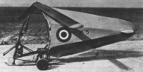
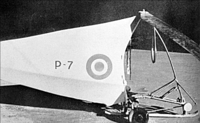
The Rotachute comprised, basically, a steel tube frame to seat the pilot, a two blade rotor with freely flapping blades and a rubber ¬mounted skid. The rotor hub was also rubber mounted, this mounting combining the functions of a control hinge with that of a damper for vertical as well as horizontal vibrations. The fuse¬lage framework was open at the front but had a tapered fairing behind the pilot to, provide stability in the yaw and pitch axes. This fairing was to be made entirely of rubberised fabric, with no framework, and was to be inflated to maintain the required shape, a feature selected to minimise the stowage space in the launching aircraft
Control was obtained by means of a hanging stick directly attached to the rotor hub. Movement of the stick tilted the entire hub and rotor. No means of yaw control were provided, turns being made simply by banking by means of a rotor tilt to left or right.
As designed in 1940, the Rotachute had a structure weight of 50 lb (22.7 kg) and could carry a useful load of about 240 lb (109 kg) comprising a pilot and parachute plus a Bren gun Mk.1 with 300 rounds. The rotor had a diameter of 15 ft (4.57 m). At the time of the trials, it was the smallest man carrying vehicle capable of controlled flight to have been built.
Contracts for the construction of prototype Rotachutes were placed by the. Ministry of Aircraft Production with F. Hills and Sons of Manchester and the Air¬work General Trading Company of Hounslow. Both companies subcontracted the production of a number of specialised components. Before flight trials began a full scale rotor was tested at the A.F.E.E. mounted on the back of a modified Ford truck. Racing up and down the runway at Ringway, this test rig provided photographic and other records on the performance of the rotor. The same lorry was then modified to carry the complete Rotachute, attached to a pylon by means of a flexible linkage which permitted 6 inches (15. 2 cm) of vertical and lateral movement, and 6 degrees of rotation about the centre of gravity in any direction. A number of runs was made with a pilot in the Rotachute, which provided preliminary information on the handling and control characteristics.
Early in 1942, enough progress had been made for the first tentative flights to take place. Throughout the development programme the policy was one of taking small steps at a time, and for the first flights, it was decided to tow the machine behind a 28 hp Humber car. Since the Rotachute had no wheeled under-carriage, a two wheeled truck was used, to which the aircraft was lightly attached. As soon as flying speed was obtained, the pilot released the restraining cable, remaining directly attached to the towing car.
Two trial runs at Ringway, on February 2 and 16, 1942 ended in heavy landings in which the Rotachute overturned and the blades were broken. A third run, using the 6,000 ft (1 829 m) runway at Snaith on February 24th, was little better and it was concluded that, at least for training purposes, a three point undercarriage would be needed, and that more tail fin area was required for directional stability.
These modifications produced the Rotachute Mk. II, with two small wheels carried on an axle below the centre of gravity (the forward end of the landing skid provided the third point of contact). The original rear fuselage fairing, as already described, comprised a rubber fabric bag with air scoops to maintain inflation during flight. With the need to lengthen this fairing, the frameless construction was no longer acceptable because the flexible bag might foul the rotor. Therefore the Rotachute Mk.II had a single wooden member running round the profile of the tail fin, with vertical members interspaced and covered with rubber fabric. The tailplane was wholly flexible and the entire fairing inflated through ram effect with forward speed.
Concurrently with this modification, a more conventional light wooden framework, fabric covered, was designed as an alter¬native and this was used for the Rotachute Mk. III.
The Rotachute II was first flown on May 29, 1942, towed by a Jeep. It was in free flight for only 15 seconds but made a successful landing. Five more flights were made on May 31 and three on June 1, each of two to three minutes duration. This concluded work with the Mk.II, and all efforts then became concentrated on the Mk.III. By this time, interest in the Rotachute as a substitute for a parachute had waned, but the possibility of using rotors to ferry supplies, including vehicles and tanks, from air to ground was of interest in official circles. Two Specifications were issued to cover the work in hand at the A.F.E.E. 10/42 for Hafner’s proposed Rotabuggy and 11/42 for his Rotachutes.
Towed tests with the Rotachute III began at Ringway on June 2, 1942, with two flights of four minutes each. These and several subsequent flights ended with controlled landings while still on tow, the first free landing being made successfully on June 9.
In all seventeen ground towed flights were made by the Mk. III, in which heights of up to 100 ft (30.5 m) were reached. The average take off run was 300 ft (91.4 m), the minimum take off speed was 28 mph (45 kph) and the landing run, depending on wind force, was from zero to 50 ft (15.2 m).
Proceeding to the next stage, a Tiger Moth was chosen for the initial airborne tow tests. This aircraft had already been equipped for glider towing. A 300 ft (91.4 m) cable was used, with the pilot in the rear cockpit and an observer facing rearwards in the front cockpit. On June 15th, a taxi run was made behind the Tiger Moth and then came two two minute flights on June 17th in which the Rotachute, but not the tug, became airborne. Two later flights on June 17th behind the Tiger Moth ended in releases and free landings.
In this series of trials the Rotachute III made fourteen free flights in all from Tiger Moth tows, the last being made on August 18, 1942. In the course of these flights, the machine reached a maximum height of 3,900 ft (1189 m), released at a maximum of 3,700 ft (1128 m), recorded a top speed of 93 mph (150 kph), and made one flight of 40 minutes duration. Total flight time on these fourteen sorties was 3 hr 10 min. Subsequently, numerous flights were made for pilot training, using a Jeep as the tug.
Later work with the Rotachute was concerned with development of the rotor for the Rotabuggy, and improvement of the handling characteristics, particularly a tendency to fall into slow speed turns at low speeds. The Rotabuggy was to use a rotor with fixed coning angle and two flights were made with a rotor of this type on the Rotachute III, on September 21 and 25, 1942, towed first by a Jeep and then by the Tiger Moth. For the next few months, the Mk. III was used for some test and performance flights, towed by the Tiger Moth or a Jeep. Flying at a weight of 295 lb (134 kg), the minimum rate of descent was found to be 960 ft/min (4.9 m/sec.), rather higher than had been hoped.
To increase directional stability, small fins were added at the end of the tailplane, and the modified machine became the Rotachute IV, first flown behind a Tiger Moth on April 29, 1943. Adjustable trimming tabs were later added to the fins, to reduce a tendency to yaw to port and these were first flown on May 20, 1943. On September 7, 1943, a single flight was made behind the AFEE’s Avro Tutor and then on October 18, 1943, the Tiger Moth made the last aerial tow of a Rotachute.
In the final analysis, the Rotachute had been found to be a comparatively simple machine to fly and easy to land in a very restricted area. Its drag proved to be larger than expected but overall performance was satisfactory. The operational need for which the Rotachute had originally been conceived did not materialize but from this work by Hafner and his team at the AFEE derived a great deal of today’s knowledge of light rotorcraft. One of the Rotachutes was shipped to the USA during the war.
Rotachute
Number of seats: 1
Rotor diameter: 4.57m
Height: 2.08m
Weight fully loaded: 134kg
Empty weight: 34kg
Cruising speed: 136km/h