Top speed: 63 mph Cruise: 60 mph Range: 50 sm Rate of climb: 800 fpm Takeoff dist: 200 ft Landing dist: 0-10 ft Service ceiling: 10,000 ft Engine: 2si, 45 hp hp range: 40-70 Fuel capacity: 5 USG Empty weight: 251 lb Gross weight: 550 lb Height: 8.5 ft Length: 16 ft Disk span: 23 ft Disk area: 415 sq.ft Seats: 1 Undercarriage: tailwheel
After the LW-3, the next logical step was to develop a two-place version. The prototype, based on the LW-2 and LW-3 single-place models, is a shortened version of all models. The original fuselage was designed for using an elevator for longitudinal control and, therefore, was built longer to provide ample control power at all flight speeds. With the direct (full tilting head) control, the full length fuselage isn’t required and the shorter version will be much less likely to receive damage to the tail from a rotor blade during ground operation. The horizontal tail area has been increased accordingly. Plans were available for this version. The prototype two-place, short-version, has been test flown and should be in a cosmetically completed state by early fall, 2000. It features a Rotax 914 turbo-charged engine of 115 hp. It is very smooth and very quiet.
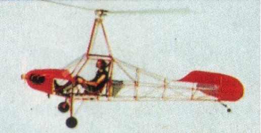
The LW-2 craft was so stable that Herron was prepared to compare it to a similar machine with a fully tilting head. Thus, LW-3 was born. This craft was built with some other changes implemented besides the control method. A shock absorbing, outrigger landing gear, and a 2180cc Volkswagen conversion, with dual ignition. This had a rotor brake and a simple electric prerotator, the centrifugal flyweights and also a control stick lock to hold the stick full forward any time the craft was operated on the ground prior to take-off and after landing. This precluded the rotor contacting the tail prior to the blades reaching stable speed prior to take-off and as the rotor slowed after landing. This aircraft flew exceptionally well from the very beginning. Any fears of it being anything less than completely stable were quickly squelched. It used the same horizontal stabilizer as LW-2 but omitted the elevator. After about 20 hours of flight, a special damper system was designed for the rotor pylon. This diminished the two-per-rev vibrations typically felt in two-biaded rotor systems.
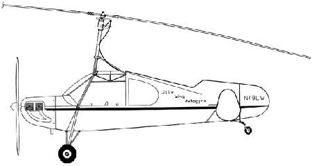
Single-seat enclosed tractor autogyro. Practically any popular engine package can be mounted to these airframes. These aircraft feature engine thrust lines below aircraft CG…No PPO problem. 100% 4130 chromoly steel construction. Pre-welded fuselage: $3,500, Plans: $175 in 2009.
Engines: Hirth 65-120 hp; 70 hp T.E.C. 2180 cc; Rotax 582, 912, 914, Rotec Radial 110 hp Propeller: Warp Drive up to 72″, Prince or Sterba 74″-76″ Rotor Blades: 25′ Dragon Wings Specifications: Min Speed 15-20 mph Cruise 60-70 mph Top Speed 100 mph Empty Weight 350 lbs, 2-stroke 575 lbs, Radial Useful Load 300 lbs Gross Weight 700-900 lbs Width 7′ Height 8’6″ Length 16′ – LW-3S, 18′ – LW-3
Main Rotor: 23 to 27 feet Blade Chord: 7 inches Length Overall: (rotor turning) 23-27 feet Length of Aircraft without Rotor installed: 18 feet (16 feet, short-versions) Wheel Track: 7 feet Wheel Base: 13 feet – (11.5 feet, short-versions) Landing Gear: Conventional (tailgear) Overall Height: 8.5 feet Cabin Width: 26 inches Cabin Height: 42 inches Cabin Length: Approx. 49 inches (single) Baggage: Small shelf aft seat(s) 10 lbs. max. Rotor Disc Area: 415 Sq. feet (23 ft.) / 573 Sq. feet (27 ft.) Disc Loading (@ gross wt.): 1.8 lb./sq. ft. single-place (23 ft.) Tailplane Area: Vertical Fin: 4.52 Sq. feet Tip Shields: (2) 1.59 Sq. feet each Rudder: 3.3 Sq. feet Horizontal Stabilizer: 8.8 Sq. feet LW-3 series (8 Sq. feet for elevator models) Control Method: Conventional rudder, fully-tilting head Rotor/horizontal tail volume ratio: 22% for long frame / 14.9% for short frame. Empty Weight: 351 lbs. w/Rotax 582-618, 2Si 540-L(two-stroke powered) / 452 lbs. w/ 2180 VW (four-stroke powered) Gross Weight: 750 lbs. Single-Place Fuel Capacity: 8.5 US gal. (single-place) Cruise Speed: 65 – 75 mph Minimum Speed: 15 – 20 mph Landing Speed: 10 – 15 mph Takeoff distance: 100-750 ft Landing Roll: 0-25 ft. Rate of Climb: Varies with powerplant, density altitude and weight. Construction: Welded SAE 4130 steel tubing, Dacron fabric covering.
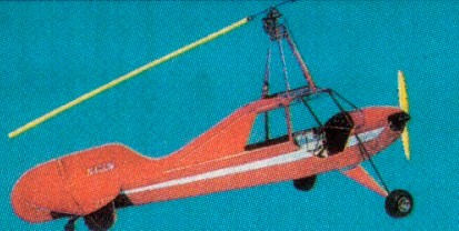
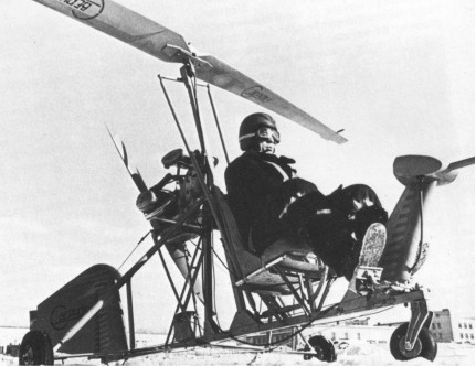
The LW-1 aircraft was taxi tested and then test flown. It flew remarkably easy. It also had no stick shake. It was, however, not a very good performer due to its weight and the small diameter rotor used for testing. It was primarily a “proof-of-concept” aircraft anyway. The concept seemed to be on target. Herron immediately began building the LW-2. This was to be an ultralight version of the LW-1. Within two months three people had it built and assembled. Basically, it was a scaled-down Piper Cub type frame built from start to finish with new 4130 chromoly steel tubing. Initial flight testing was done without paint or fabric installed. It was powered by a McCulloch drone engine (removed from an old Bensen). Its initial flights were without incident and without any difficulty. After a few flights it was stripped down and painted, and reassembled, still without fuselage fabric. It an additional 15 hours before tearing down for a complete fabric job to get it ready to show. This took it out of the “ultralight” category which limited it to 254 Ib. Most people had a negative attitude toward the McCulloch, so it was replaced with a water-cooled AMW engine of 70 horsepower. This engine featured dual ignition, alternator and electric start. This aircraft was shown at the PRA International Convention and EAA’s Oshkosh in 1995, ’96 and ’97. It proved to be a remarkably stable craft. It was somewhat difficult to handle on the ground in a strong wind due to the inability to move the rotor in the fore-aft direction. Herron learned to deal with this by turning the aircraft sideways to the wind and tipping the disc laterally, into or away, from the wind as was required. This craft was so stable that it was compared it to a similar machine with a fully tilting head. Thus, LW-3 was born.
Cierva had patented the concept of aligning the propeller thrustline with CG (For increased longitudinal stability) very early in the Autogiro’s development. The missing ingredient in the Bensen type gyro was the horizontal tail. The Autogiros of old had huge horizontal tails and tractor mounted propellers which were located in the center of aircraft drag and center of gravity. These aircraft were forgiving and pitch-stable. Herron “copied” Don Juan de la Cierva Codorniu…..the father of practical rotorcraft. The first 2 prototypes utilized elevators for longitudinal (pitch) control. On these craft he locked the rotorhead in the fore-aft position and designed a means of trimming it for fine adjustments. Side-ways tilting of the head was used for lateral control. The first of these prototypes was the LW-1, built it from a wrecked Piper airplane fuselage. The rotor pylon was attached to the fuselage through four large isolation dampers, and a wide outrigger type landing gear with oleo struts. This aircraft was powered by a Continental 0-200 engine of 100 horsepower. Lateral control was accomplished by using push-pull cables directly connected to the control torque tube. Centrifugal flyweights were developed for the rotorhead to prevent the two-bladed rotor from flapping into the tail at low rotor speeds, and an automotive starter for a prerotator to start the blades. This aircraft was taxi tested and then test flown. It flew remarkably easy. It also had no stick shake. It was, however, not a very good performer due to its weight and the small diameter rotor used for testing. It was primarily a “proof-of-concept” aircraft anyway. The concept seemed to be on target.
1995-2009: 746 Highway 89 N, Mayflower, AR 72106, USA.
Ron Herron of Little Wing Autogyros Inc began involvement with gyros by building a Bensen B-8M in 1975. Became a little concerned about the continued problem of “Pushovers”, he sold the gyro and began to research the history of the Autogiro and found the original Autogiros flew for 10 years before anyone was ever killed in one. Cierva had patented the concept of aligning the propeller thrustline with CG (For increased longitudinal stability) very early in the Autogiro’s development. The missing ingredient in the Bensen type gyro was the horizontal tail. The Autogiros of old had huge horizontal tails and tractor mounted propellers which were located in the center of aircraft drag and center of gravity. These aircraft were forgiving and pitch-stable. Herron “copied” Don Juan de la Cierva Codorniu…..the father of practical rotorcraft. The first 2 prototypes utilized elevators for longitudinal (pitch) control. On these craft he locked the rotorhead in the fore-aft position and designed a means of trimming it for fine adjustments. Side-ways tilting of the head was used for lateral control. The first of these prototypes was the LW-1, built it from a wrecked Piper airplane fuselage. The rotor pylon was attached to the fuselage through four large isolation dampers, and a wide outrigger type landing gear with oleo struts. This aircraft was powered by a Continental 0-200 engine of 100 horsepower. Lateral control was accomplished by using push-pull cables directly connected to the control torque tube. Centrifugal flyweights were developed for the rotorhead to prevent the two-bladed rotor from flapping into the tail at low rotor speeds, and an automotive starter for a prerotator to start the blades.