Lawrence J. Lesh made his first flight in a glider in Chicago in 1906 at the age of 14. In 1908 he had an accident withhis glider at Morris Park, New York, which confined him to hospital for over seven months. Though only a boy of 17 years, Lesh had done a great deal of experimental gliding from the age of 14. He held the world’s record, having made a flight of more than six miles in length over the St. Lawrence River, towed by a motorboat.
Glider
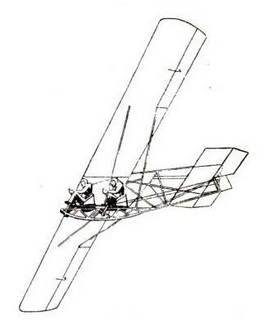
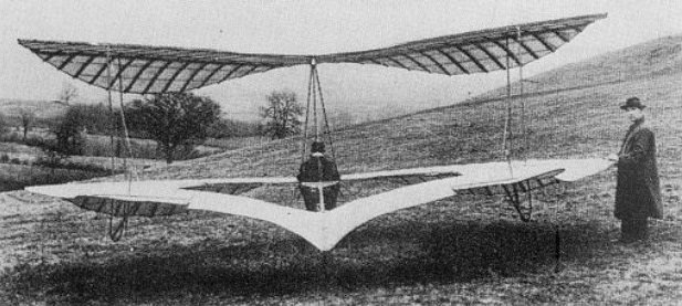
Le Prieur-Aihara Glider / Daiichi Senior High School Glider
An earlier glider had been designed by Le Prieur based on a drawing from a French pamphlet. But when a test flight failed, Le Prieur turned to his friend Aibara for assistance, and Aibara brought in Tanakadate, an aviation pioneer in his own right, to help with the design.
The glider was developed by Yves Le Prieur, a military attache at the French Embassy in Tokyo, Lieutenant Shiro Aibara of the Japanese Navy, and Professor Aikitsu Tanakadate of Tokyo Imperial University’s School of Science, now the University’s Faculty of Science (at the time the University of Tokyo was named Tokyo Imperial University). Also known as the Aihara-Le Prieur, built by Japanese Lieutenant Shiro Aihara and French 2nd Lieutenant Le Prieur using bamboo for the structure.
The team first planned to use an automobile to pull the glider, but on the day of the trial the car broke down and didn’t make it to the test site. Instead they put a small boy aboard and a group of students pulled on the cable attached to the craft.
On the morning of December 5, 1909, a bamboo-framed and white cloth-covered glider was hauled onto the Daiichi Senior High School’s athletic field, Ueno Park, Toyko, today a part of the University of Tokyo’s Faculty of Agriculture on the Yayoi campus. A large number of students took hold of a rope attached to the glider, and then ran as fast as they could, pulling the glider behind them. Soon, spectators witnessed the craft, with a boy aboard, ascend slowly and fly at a height of 3.6 meters for a distance of some 15 meters before drifting down to a smooth landing. “
This was apparently the first, though unofficial, glider flight in Japan, and it represents the very beginning of airplane research.
In the subsequent December 9 test flight, piloted by Le Prieur himself, a car was used, which drove along a street near Shinobazu Pond, Tokyo, towing the glider. This was the first certified fixed-wing aircraft flight in Japan.
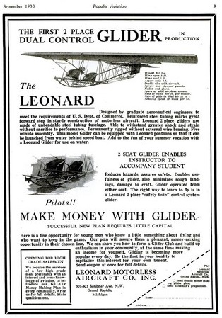
Leonard Motorless Aircraft Glider
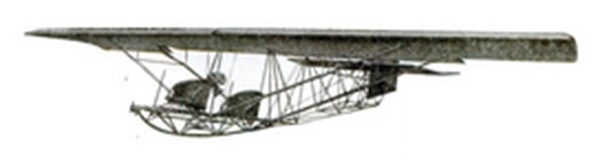
Billed as the first two seat glider to enter production, the 1930 Leonard Motorless Aircraft Company glider of 1930 was designed by graduate aeronautical engineers to meet the requirements of the US Dept of Conmmerce.
The entire fuselage is constructed of steel tubing, welded at all joints and with bals wood inside. The wings are cloth covered and braced with spruce ribs.
Able to be flown from either seat with dual controls fitted, the glider was for sale in 1930 for $550.
Wingspan: 34 ft
Wing chord: 5 ft
Aspect ratio: 6.8
Empty weight: 210 lb
Landing speed: 19 mph
Auto tow ROC: 800 fpm
Glide ratio: 15-1
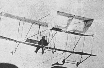
Lee-Richards Biplane
Englishman, G.J.A. Kitchen of Lancaster, patented a circular or annular wing and sold the rights to Cedric Lee, who built an annular winged biplane powered by a 50 hp Gnome rotary engine in 1911. This ‘Kitchen Doughnut’ was wrecked by a gale during tests. Lee and his engineer Tilghman Richards continued to experiment with gliders and with wind tunnel test models at the National Physical Laboratory and soon discovered that the circular wing had some very desirable properties. It continued to provide lift at extreme angles of incidence, and had a gentle stall. Furthermore, a round wing could have a span or diameter less than half that of a conventional surface of the same lifting area.
In 1912 the Lee-Richards annular wing was a circular planform with a hole diameter half span. The powered portotype was a biplane, and they tested it at Middleton Sands, Heysham in 1911. This was supposed to be a very stable configuration, and a later version flew for 128 hours, but the prototype had run into a gully, and then been destroyed when the hanger blew down in a gale. They had been changing the leading-edge camber shape, but were unable to decide which was best, so before rebuilding they tried two models, span 4.7 ft, flown indoors. Extra camber seemed to give a flatter glide angle, but the other person said that this was due to better launch technique. So they went full scale.
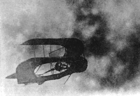
The glider was a biplane, but the upper wing was only the front half of the circle. Elevators behind the wing were also operated differentially for roll control and a fin and rudder were added later. The pilot’s seat was in the hole, and the breeze.
Launch was by catapult from a track, pulled by a rope tied to a dropping weight within a tall tripod. The site was Sellet Banks, an east-facing slope 117 feet above the River Lune near Kirby Lonsdale.
The glider made many successful glides. It was stable and controllable, was banked into turns, and even taken through the stall to 30 degrees nose up, when it pancaked steadily. They often flew in winds of 20 mph, and even 40 mph.
On the final day of flying at the end of trials in December 1912, Cedric Lee made a soaring flight in a strong wind. Cine film was taken, used in the opening clips of “Those Magnificent Men”, and stored in the Science Museum.
A non-flying replica of the powered version is at the Newark Museum.
Wingspan: 22 ft
Wing area: 400 sq.ft
Empty weight: 215 lb (later 390 lb)
Gross weight: 710 lb
Glide ratio: 1-8
LeBris Glider
In 1855 French sea captain Jean-Marie LeBris built a glider based on his observation of the albatross, the seabird with huge wings.
LeBris’ monoplane had a wingspan of 49 ft and total wingarea of 215 sq.ft.
The whole thing was set on a cart and drawn downhill by a horse. It flew briefly, scaring LeBris, and then crashed, breaking his leg.
LeBris gave up aeronautics.
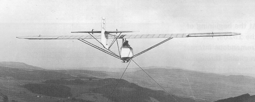
Laubenthal Württemberg / Akaflieg Darmstadt Württemberg
The Akademische Fliegeruppe Darmstadt also received some orders from individuals or club and these, built in ones or twos, were client named, received no D- number and brought welcome funds to the group. These, too, were sometimes also designed by student teams and often built by them.
The Württemberg was made for Wolf Hirth, who named it after his home state. The Württemberg was a high, cantilever wing aircraft. Its wing, like the rest of the aircraft was wooden and covered with a mixture of plywood and fabric. It was built around a single spar, with ply covering from it around the leading edge forming a torsion-resistant D-box. Behind the spar the wing was mostly fabric covered. In plan there was a rectangular centre section that filled about 40% of the span and tapered outer panels tapering to elliptical tips. The ailerons filled about 40% of the span from the tips.
The Württemberg’s wing was mounted over the fuselage on a low, ply covered pylon which sat on top of the fuselage and extended well behind the wing trailing edge, gradually decreasing in height. Its open, unscreened cockpit was partly under the leading edge. The fuselage was ovoid in cross section, tapering and becoming more pointed on its underside aft. It was entirely ply covered. All tail surfaces were built in a similar way to the wing. Both rudder and elevators were all-moving and balanced, with straight edges, rounded tips and with their short mountings faired into the fuselage. The rudder extended down to the keel, so a generous cut-out in the elevators was provided for its movement. The Württemberg had a short landing skid under the forward fuselage and a spring type tailskid.
A second Württemberg was completed in 1929 at the Klemm Leichtflugzeugbau GmbH (“Klemm Light Aircraft Company”) for the Württembergischer Luftfahrt-Verband (Aeronautical Association Württemberg) at Stuttgart, with slightly greater wing area and a shorter fuselage.
First flying in 1927, in 1928 Hirth flew the Württemberg in France at the International contest at Vauville, on the Channel coast near Cherbourg, with great success. Glider flight here followed the coast over sandhills and relied on slope lift from a West wind; the Württemberg was suited to the weak wind that blew during the competition. He won prizes for the greatest height gain (327 m (1,073 ft)), straight-line distance (29 km (18 mi)), height (1,244 m (4,080 ft)) and for the number of flights lasting more than 30 minutes (10).
Württemberg (1927)
Wingspan: 15.20 m (49 ft 10 in)
Wing area: 15.75 m2 (169.5 sq ft)
Aspect ratio: 14.6
Airfoil: Göttingen 535
Length: 6.465 m (21 ft 3 in)
Empty weight: 149.25 kg (329 lb)
Gross weight: 235 kg (518 lb)
Wing loading: 15 kg/m2 (3.1 lb/sqft)
Crew: One
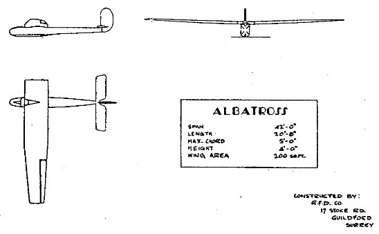
Latimer-Needham Albatross / R.F.D. Albatross
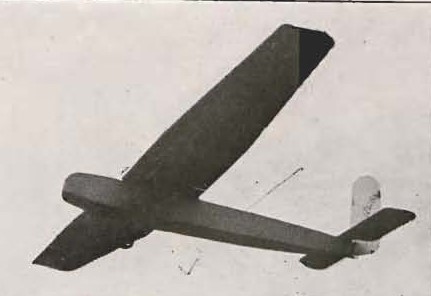
The RFD Company constructed the Albatross to C.H. Latimer-Needham’s design, the first British-designed and built sailplane. It was a conventional wooden single-seat aircraft, its cantilever high wing having a constant chord centre section and outboard straight-tapered panels from about mid-span. Ailerons were fitted from the wing tips over most of the outboard sections but here were no flaps or air brakes. The wing was mounted with slight dihedral on top of the fuselage, which was rectangular in cross section and tapered only a little towards the tail. There were no fixed rear surfaces, both elevators and rudder being all moving. The elevator, mounted on top of the fuselage, had constant chord apart from a cut-out for rudder movement; the latter was tall, with a vertical leading edge and curved trailing edge.
The Albatross’s single-seat open cockpit was at the leading edge of the wing, with a fairing behind the pilot’s head reaching aft beyond the trailing edge. Originally it landed on a skid which was part of a V-shaped ventral extension of the fuselage, running from just behind the nose about half the length of the aircraft. Twin landing wheels were fitted later.
Only one Albatross was built, receiving its Certificate of Airworthiness in October 1930. It appeared at the Glider Show held at The Royal Agricultural Hall, Islington in May 1931.
One owner was A.E. Coltman of the Leicestershire Air Sports Club who did some soaring at Sutton Bank.
It was later sold to Edwin S Griffis, who was killed when the wing failed when it was being launched at the Furness Gliding Club site at Ireleth on 12 August 1936.
Wingspan: 42 ft 0 in (12.8 m)
Wing area: 180 sq ft (16.72 m2)
Length: 20 ft 8 in (6.3 m)
Aspect ratio: 10
Airfoil: Göttingen 535
Empty weight: 205 lb (93 kg)
Gross weight: 360 lb (163 kg)
Lanzalone Aulanz
This Argentine single-seater motor glider was designed and is being built by Senor Augusto Lanzalone of Rosario in Santa Fe province, who has also formed the Asociacion Argentina de Constructores de Aviones Experimentales – Avex for aircraft like the Aulanz. Not only has Senor Lanzalone designed and built the engine for it – a 30hp Lanzalone two-cylinder two-stroke inverted inline motor of 700cc – he has evolved his own special alloy for the construction of the airframe. This is known as Alcusing, and consists of aluminium with portions of copper, nickel, magnesium, silicon and chrome; the two-blade variable pitch propeller is also made of this material.
The Aulanz is a conventional low-wing monoplane of semi-monocoque Alcusing structure, with the engine in the nose and a retractable rubber-sprung monowheel under the wing leading edge, plus a tailskid. The total fuel capacity is 20 litres (4.4 Imp gallons). By the spring of 1973 the prototype’s fuselage and tail unit were completed, and construction of the remainder had been proceeding slowly.
Span: 40 ft 8.25 in
Length: 17 ft 8.5 in
Height: 6 ft 1.75 in
Wing area: 125.9 sqft
Aspect ratio: 13.1
Max weight: 617 lb
Lange Antares 20E / Antares 23E / E1 Antares
The E1 Antares is a composite single-seat self-launching powered glider with an electric motor. The E1 Antares (also known as the “Antares 20E”) is an all new design with a shoulder-mounted 20 metre span wing with flaperons and winglets. The aircraft is constructed from CRP/GRP-composites, with a T-shaped horizontal tailplane with fin and elevator, Schempp-Hirth airbrakes on the upper wing, and wing water ballast tanks. The retractable landing gear is equipped with brake and spring suspension.
The EA 42 electric drive system consists of the electric motor EM42, power-electronics LE42, engine control system EDCS2 and the sensor, data and power cables. The 42kW brushless DC electric motor is powered by a SAFT lithium-ion battery system, spilt into two packs positioned in the leading edge of both wings and composite two-blade fixed-pitch two metre diameter propeller.
E1 Antares EASA Type Certificate A.092, and includes the EA 42 engine based on EASA Type Certificate E.015 and the LF-P42 propeller based on EASA Type Certificate P.015.
The Lange EA 42 is an electrical aero engine designed for self launching gliders. It is produced in Germany by Lange Aviation for their Antares 20E glider.
E1 Antares
Engine: Lange EA 42
Propeller: Lange LF-P42
MCTOW: 660 kg (with water ballast)
MCTOW: 602 kg (without)
No. of Seats: 1
Lanaverre Industrie
The French company Lanaverre Industrie built 35 Schempp-Hirth Cirrus designated CS 11/75 L St. and CS 11/78 L St. These ships overlap the German serial numbers with serial numbers beginning at one.
