A 1936 parasol-wing (12 m) single-seat Zögling-type glider, 2 built
Glider
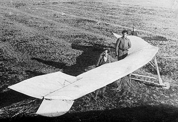
Lombarda Bonomi BS-02 Balestruccio
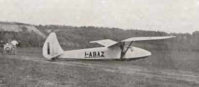
The Balestruccio was a single seat glider with a high aspect ratio gull wing built in four parts. The two inner panels, straight edged with constant chord and carrying dihedral, joined on top of the fuselage, their extremities braced from the lower fuselage with flat steel V-struts, encased in faired wood to reduce drag and assisted on each side by a pair of jury struts. The upper end of each strut was attached on one of the two wing spars. The outer wing panels were straight tapered, with rounded tips. There were differential ailerons on the outer trailing edges and flaps inboard.
The fuselage of the Balestruccio was hexagonal, with deep, near vertical sides. Its comfortable cockpit was immediately in front of the wing leading edge and was originally provided with a wooden canopy with small side openings, similar to that used on the German DFS Fafnir, but this was later replaced with a more conventional open arrangement which provided better all-round visibility. A single, sprung skid and a tail bumper provided an undercarriage. The fuselage tapered aft to a mid-mounted horizontal tail consisting almost entirely of the elevator; although this had straight leading edges, a combination of their slight sweep and the full, rounded trailing edges gave the planform an almost elliptical appearance. There were aerodynamic balances and a large cut-out for rudder movement. As first constructed, the vertical tail was rather similar, with a small fin and a full, deep, curved, balanced rudder which extended slightly below the keel. Later, with the fuselage shortened by one frame or about 700 mm (28 in), the Balestruccio was given a new, angular fin and rudder with straight taper and square tip. Like the old rudder, this was also balanced and deep, though extending only to the keel. The original horizontal tail was retained.
The Balesruccio proved to be versatile and efficient and was flown by Vittorio Bonomi and Enrico Rolandi from Mottarone and Campo dei Fiori di Varese. On 18 December 1932 Rolandi flew it for 25.8 minutes, setting a new Italian national endurance record, covering 15.7 km (9.8 mi) and winning the Castiglione Trophy. As late as 1937, it was demonstrating its performance in Asiago.
Wingspan: 18.00 m (59 ft 1 in)
Wing area: 17.14 m2 (184.5 sq ft)
Aspect ratio: 18
Wing section: Gottingen 549
Length: 8.33 m (27 ft 4 in), later 7.55 m (24 ft 9 in)
Empty weight: 125 kg (276 lb)
Gross weight: 205 kg (452 lb)
Wing loading:11.50 kg/m2 (2.36 lb/sq ft)
Maximum glide ratio: estimated 24:1
Rate of sink: 0.58 m/s (114 ft/min)
Crew: One
Lombarda (Aeronautica) Sa
Italy
Most Aeronautica Vittorio Bonomi construction was carried out by Aeronautica Lombarda – hence the common use of Aeronautica Lombarda BS-28, etc
In 1937, Lombarda bought out Aeronautica Vittorio Bonomi, building light aeroplanes and gliders. After the Abyssinian War turned to military aircraft production. During Second World War built Heinkel He 111 and Loire 130.
Lohner-Umlauff Rodelgleiter / Sleigh-glider
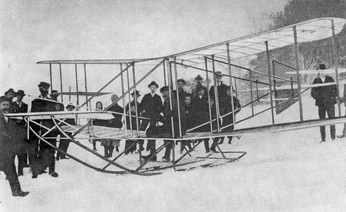
Ordered by Rittmeister Hans von Umlauff and built by Lohner with Wright-like dihedral wings, the Sleigh-glider, or Skiglider was tried over the winter of 1909/10 at Waldegg at Lower Austria, with some success.
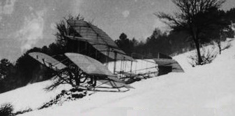
The longest flight achieved by Von Umlauff’s biplane glider was 75 metres during testing at Semmering, Niederösterreich, Austria, on February 16, 1910.
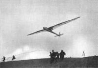
Lippisch Wien
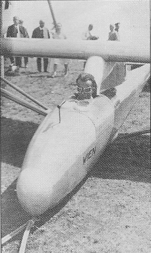
To remain competitive with the latest designs coming from the German universities, Robert Kronfield asked Alexander Lippisch, the Professor’s designer, for an improved version with better performance and handling. Lippisch’s response was an elegant sailplane that Kronfeld named Wien after his home town. The Wien kept the layout of the Professor, with pylon-mounted single-spar wings braced with faired struts, but the span was increased by 3.0 m (9 ft 10 in), raising the aspect ratio from 14 to 19.6. The fuselage was redesigned to have a smooth ovoid section, finer aft than on the Professor and fitted with a more aerodynamically refined fin and rudder.
Both designs used a plywood-covered D-box forward of the spar, with fabric covering behind, and their 2.50 m (8 ft 2 in) half span, parallel chord inner wing panels were similar, though close to the fuselage the Wien’s wing was strengthened with full chord plywood skin. The V-form bracing struts linked the extremes of these panels to the lower fuselage. The extra span of the Wien was in the double straight-tapered outer panels, which continued out to finer, rounded tips. Ailerons occupied the whole trailing edge of these sections.
The Wien’s open cockpit was ahead of the wing leading edge. There was no windscreen, and the instruments, including the still novel variometer, were displayed horizontally, inset into the fuselage immediately in front of the pilot. The undercarriage consisted of a single enclosed skid and a small spring tailskid. The rear fixed surfaces, ply covered, were very narrow, though the root of the fin was carefully faired into the fuselage. The tapered control surfaces were fabric covered.
The Wien was capable of utilizing both ridge lift and thermals. Kronfield used both methods in a series of ground breaking and often record setting flights between 1929 and 1931, learning much about thermal flying. On 15 May 1929 he made the first glider flight of more than 100 km (62 mi), largely ridge flying but with some thermal soaring. This was followed by at least three world distance records, the last between the Wasserkuppe and Marktredwitz, a distance of 164 km (102 mi) flown on 24 August 1930. Some very significant though not record breaking flights of about 160 km (100 mi) were made in August 1931 which used thermals alone and showed that on some days the distance that had to be flown between thermals was short. This was new information which, as it became widely known, opened up the potential of cross-country soaring.
Kronfeld also set two glider altitude records, the second flown on 30 July 1929 in thunderous conditions to a height of 2,560 m (8,399 ft).[2] At the invitation of the British Gliding Association he and the Wien made a series of demonstration flights on a tour of England in the Summer of 1931. During it he flew over London along the Thames and also won a £1,000 prize donated by the Daily Mail for a cross Channel flight. The North -South crossing, followed by a return flight, was made in July 1931; these did not use thermals but were direct glides from about 3000 m (9,840 ft) after an aero-tow.
Wingspan: 19.10 m (62 ft 8 in)
Wing area: 18.6 m2 (200 sq ft)
Aspect ratio: 19.6
Airfoil: Root, Göttingen 549 modified with thickened nose and increased camber
Length: 7.95 m (26 ft 1 in)
Empty weight: 158 kg (348 lb)
Gross weight: 248 kg (547 lb)
Wing loading: 13.8 kg/m2 (2.8 lb/sq ft)
Crew: One
Lippisch 272 Fafnir
Günther Groenhoff demonstrated his skill and courage while conducting research for a Munich meteorology conference in May 1931. On a mission to gather weather data, he installed various instruments on his Alexander Lippisch built “Fafnir” model 272 glider and was towed to altitude by a powered aircraft piloted by pilot Peter Reidel. As they approached towering cumulus clouds over Munich, Groenhoff’s Fafnir was released to his fate. For the next eight hours, he was bounced and buffeted around the thunderstorm amid lightning flashes, hail and torrential rain, all the while collecting valuable information on weather conditions. Many times he flew in the blind. His journal indicates that he experienced one rapid descent in zero visibility to emerge from the cloud to see the ground only a few hundred feet below. He managed to bank and return to the front side of the thundercloud. He wrote, “as soon as the storm reached me, some powerful force pulled the plane straight up into the center of the clouds. It seemed to me as if I were riding an express elevator of a high skyscraper.”
After soaring with the storm for eight hours, he had traveled 240 miles and finally landed on a riverbed, coming to rest a few meters short of an electric line near Kaaden, Czechoslovakia. Groenhoff wrote that he was gratified that he was able to bring home “the rich material for meteorological research.”
Back at Wasserkuppe on July 23, 1932, Groenhoff once again soared into the strong, turbulent winds of a thunderstorm. However, his good fortune had run out. The rudder of his Fafnir snapped and he crashed on the west slope, dying instantly. He was 23 years old.
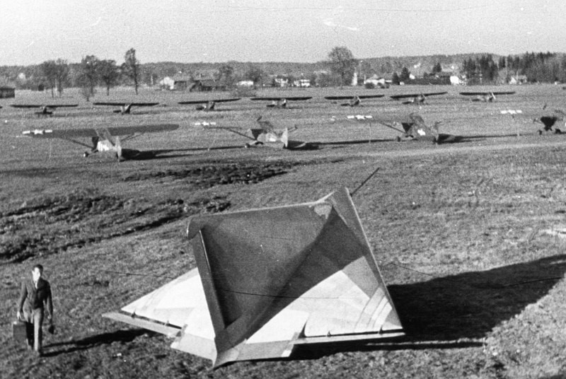
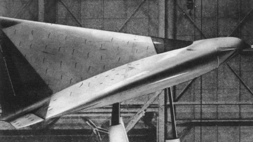
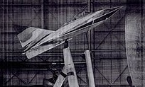
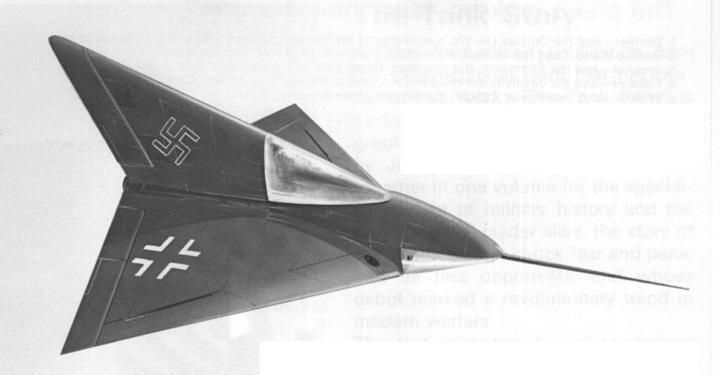
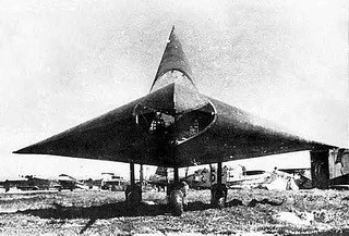
Lippisch DM-1
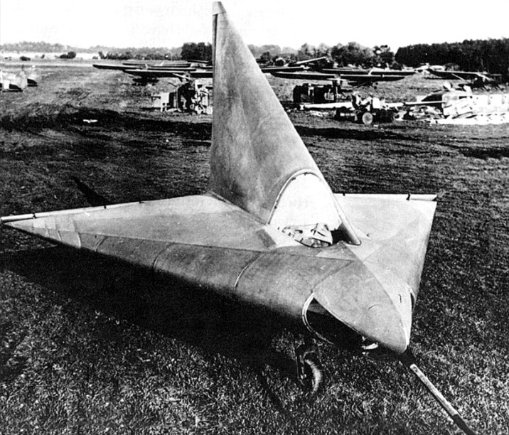
During World War II, Dr. Alexander Lippisch proposed a ramjet propelled point defence fighter, the Lippisch P.12/13a. It was a sharply-swept delta flying wing with the engine buried the a thick, blunt-nosed wing. The pilot was accommodated in the forward section of the tail fin, which was as thick as the wings and almost as large. A scale model was successfully flown at Spitzerberg, near Vienna.
Lippisch himself lost interest in the design and began work on the P.13b with a different wing, but he was approached by students of Akaflieg Darmstadt and Akaflieg München, who asked for vital war work so that they would not be drafted. By this time in 1944 Lippisch realised that the war was hopeless and was happy to oblige, arranging for them to build a full-scale aerodynamic test glider for the P.12/13a project.
Construction was begun at the workshop of the Akaflieg Darmstadt, as the Darmstadt D-33. The workshop was bombed in September 1944, so the part-built airframe was moved to the Akaflieg München workshops at Prien am Chiemsee, where it was redesignated the DM-1 (for Darmstadt-München 1). At Prien, Wolfgang Heinemann and Hans Zacher from Darmstadt, with Klaus Metzner and Hermann Nenninger from Munich, continued the work.
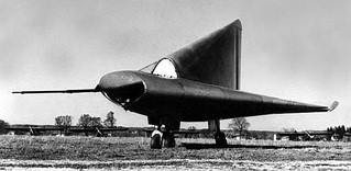
The DM1 was a single-seat glider made from steel tubing, plywood and bakelite impregnated plywood. The cockpit canopy was integrated into the fin leading edge. Launching the DM-1 was to be by piggy-back or aero-tow.
After occupation by U.S. Troops in May 1945, work continued at the DM-1 on behalf of the U.S. military government, with General Patton and Charles Lindbergh visiting Prien to see the project.
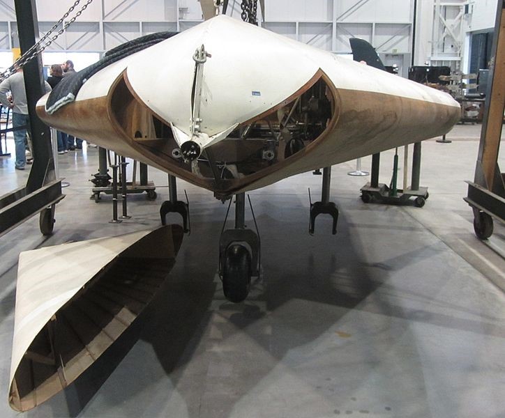
Completed in early November 1945, the DM-1 was shipped in a wooden box to Langley Field in Virginia where the flow behaviour of the DM-1 was examined in the NACA (National Advisory Committee for Aeronautics, forerunner of today’s NASA) full-size wind tunnel.
When tested at Langley, the DM-1 was found to perform poorly. It generated significantly less lift at low speeds than small-scale models had suggested. The cause proved to be vortex lift generated by the models which, due to its much higher Reynolds number, the full-size aircraft did not produce.
As a consequence it underwent a programme of modifications. Like all Lippisch deltas it had a thick wing with a blunt leading edge. A strip was fixed along the leading edge to simulate a sharp profile. This created the vortices seen on the model and greatly increased the lift. The origin of modern vortex lift theory may thus be traced to the NACA study and the modified DM-1.
The large and even thicker vertical stabilizer was removed and replaced with one of much smaller size, along with a cockpit canopy from a Lockheed P-80 Shooting Star in a more conventional position. Together with improvements to the elevon hinges, this significantly reduced overall drag.
After completion of testing the DM-1 was retired to the National Air and Space Museum, Smithsonian Institution in Washington, D.C. for storage at the Paul E. Garber Preservation, Restoration, and Storage Facility.
Besides the NASA modifications, the Akafliege Darmstadt and München defined some powered designs for a development programme derived from the DM-1.
DM-1 (Lippisch). Glider as originally built but never flown, with thick wings and large tail.
(NACA). Glider as modified with leading-edge strip, small thin fin, conventional cockpit and sealed elevon hinges.
DM-2. Larger, supersonic test plane with 8.5 metres (27 ft 11 in) span, 8.94 metres (29 ft 4 in) length and prone pilot. Powered by a Walther liquid-fuelled rocket. All-up weight 11,500 kilograms (25,400 lb).
DM-3. Developed version of the DM-3 with pressure cabin and more powerful Walther C engine.
DM-4. Engine flight testbed, initially fitted with a Walther C. Airframe weight (without engine) 2,500 kilograms (5,500 lb)
DM-1
Wingspan: 6 m (19 ft 8 in)
Wing area: 19 m2 (200 sq ft) ca
Length: 6.32 m (20 ft 9 in)
Height: 3.25 m (10 ft 8 in)
Empty weight: 375 kg (827 lb)
Gross weight: 460 kg (1,014 lb)
Maximum glide ratio: 7
Crew: 1
Lippisch 1929 Glider
Alexander Lippisch in 1929 built a flapping wing glider on which the wing movement was operated by the pilot’s legs in the manner of one of those rowing machine. Lippisch’s aircraft was launched by a rubber bungee, and was therefore man assisted rather than man-powered, but it did manage flights up to 275 m (300 yards).
Lippisch Falke Rva
Soaring plane, Germany, 1929
Length : 17.257 ft / 5.26 m
Height: 5.741 ft / 1.75 m
Wingspan : 43.307 ft / 13.2 m
Crew : 1
Lippisch 1923 Glider
Alexander Lippisch designed his first tailless glider in 1921.
