The Ku-1 was succeeded by the Ku-2, with the major modification being that the new glider had a transparent nose, a single boom and a longer fuselage.
It did not go into production.
Glider
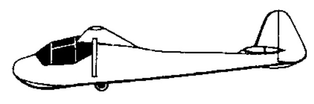
Maeda Ku-1
Professor Hirosho Sato of the Imperial university engineering college at Kyushu designed an assault glider for the Imperial Japanese Army (IJA) in response to news of airborne assaults in Europe.
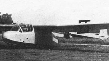
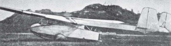
The Ku-1 was built almost entirely from wood / plywood and was a high-wing glider with twin boom tail sporting a fin and rudder at the end of each boom, with a tail-plane and elevator between the boom ends. The fuselage pod was given a streamlined shape, but with flat sides and a cockpit for two forward of the wing. The undercarriage consisted of two spatted main-wheels on short axles either side of the fuselage, with skids at nose and tail ends of the fuselage pod. The booms, attached to the wing centre-section, were wire-braced horizontally and the fins were braced by short struts on the inboard faces. Passengers and cargo were housed in the cabin below the wing, aft of the cockpit. The three-piece wing consisted of the centre-section, attached to the fuselage pod and two outer panels which were tapered and carried the ailerons for roll control.
The prototype was manufactured by Maeda Aircraft Corporation designated Ku-1 (Ku – from Kakku – to glide) and first flew on 9 January 1941. The Ku-1 was tested at the Tachiari military airfield at Kyushu on 1 September 1941. Once accepted for production the glider was given the long designation Maeda Army Type 2 Small Glider.
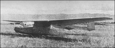
It was primarily used for training, and was superseded by the Kokusai Ku-7, which was effectively a scaled-up version of the design. Approximately 100 were produced.
Variants:
Ku-1-I
Baseline production glider;100 built.
Ku-1-II
Transparent nose, single tail boom and longer fuselage, prototype only.
Ku-1-III
An aerofoil section fuselage with tapered wings, prototype only.
Specifications:
Ku-1
Capacity: 8 troops, equipped / 600 kg (1,320 lb) cargo
Length: 9.75 m (32 ft 0 in) fuselage
Wingspan: 16.76 m (55 ft 0 in)
Wing area: 30.1 m2 (324 sq ft)
Aspect ratio: 9.7
Empty weight: 698.5 kg (1,540 lb)
Gross weight: 1,297 kg (2,859 lb)
Never exceed speed: 177 km/h (110 mph, 96 kn)
Maximum towing speed: 129 km/h (80 mph; 70 kn)
Crew: 2
Payload: 6-8 paratroopers or 500 kg
Lutz Glider
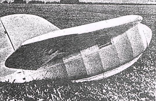
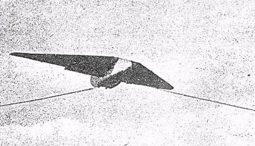
As a result of relaxed laws for glider building in Germany, this $100 midget tailless model was built by Werner Lutz of Giessen, Germany, circa 1951.
It has a 20 ft wingspan and a vertical rudder but no elevators. The pilot looks through windows.
Lutz, Werner
Giessen
Germany
Glider builder circa 1951.
Luty Ky-542 K Stosser
Designed by Paul Luty, Krefeld
Wing span: 12.8m
Wing area: 14sq.m
Aspect ratio: 11.7
Empty Weight: 307kg
Gross Weight: 475 kg
Wing Load: 33.9 kg/sq.m
L/DMax: 26 75 kph
MinSink: 0.90 m/s 65 kph
Airfoil: Go 549 mod
Seats: 2
No. Built: 1
Luftsport-Club Friedrichshafen LCF-2
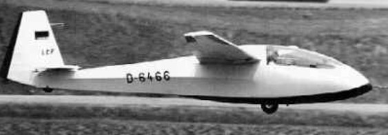
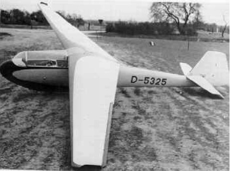
This single-seat Club Class sailplane is intended for use as a trainer, for competition flying and for aerobatics; it was designed in 1971 as a successor to the earlier LO 100 and the prototype was built in approximately 4,000 hours by five engineer members of the Luftsportclub der Zeppelinstadt Friedrichshafen. It first flew on 22 March 1975 and won first prize at that year’s meeting of the CUV or Oskar-Ursinus-Vereinigung, Germany’s equivalent of the Experimental Aircraft Association.
The cantilever shoulder wings are single-spar wooden structures, with Conticell foam ribs and plywood covering; there are Schempp-Hirth air brakes on the wing upper surfaces. The oval-section fuselage is a welded steel tube structure with glassfibre covering of the nose section and fabric covering of the rear half. The plywood tail unit is filled with Conticell foam, and the landing gear consists of a semi-recessed non-retractable monowheel and a tailwheel. The pilot sits under a one-piece flush fitting cockpit canopy.
There were plans for production of the LCF II by Scheibe if sufficient orders for it had been received, but these were dropped.
LCF 2
Wing span: 13m / 42 ft 7.75 in
Wing area: 10sq.m / 107.6 sqft
Aspect ratio: 16.9
Wing section: Wortmann FX-60-126
Length: 6.35 m / 20 ft 10 in
Height: 0.9 m / 2 ft 1.5 in
Empty Weight: 190kg / 419 lb
Gross Weight: 300kg / 661 lb
Water ballast: None
Wing Load: 30kg/sq.m / 6.14 lb/sq ft
Max speed: 174 mph / 135 kt / 250 km/h
Max aero-tow speed: 105 mph
Stalling speed: 33.5 kt / 62 km/h
MinSink: 0.70 m/s / 2.30 ft/sec at 68 kph / 42.5mph / 36.5 kt
Best glide ratio: 30:1 at 53 mph / 85 kph / 46 kt
No. built: 1
Seats: 1

Luenger Beta 1

The Beta 1 was designed by Hans Luenger and Josef Kohler with the intent of being the first US production fiberglass sailplane. The semi boom-and-pod fuselage was composed of two fiberglass half-shells that join top and bottom. It featured a fully-reclined pilot position, T-tail with mass-balanced elevators, fixed gear and Schempp-Hirth speed-limiting dive brakes. The Beta 1 has been donated to the National Soaring Museum.
Wing span: 17m / 55.8ft
Wing area: 13sq.m / 140sq.ft
Aspect ratio: 22.3
Empty Weight: 313kg / 690lb
Gross Weight: 413kg / 910lb
Payload: 100kg / 220 lb
Wing Load: 31.91kg/sq.m / 6.06lb/sq.ft
L/DMax: 38 93 kph /50 kt / 58 mph
MinSink: 0.61 m/s / 2.0 fps / 1.18 kt
Seats: 1
No. Built: 1
Airfoil: Wortmann FX 61-184/160
Ludlow Aeroplane No.12
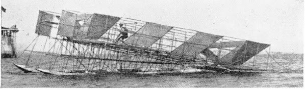
Israel Ludlow’s Jamestown Exposition Glider on floats during its unsuccessful trials on Hampton Roads, piloted by the aeronaut Capt. T. T. Lovelace and towed by the tug Potomac on August 21, 1907.
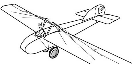
LPW / Leeming-Prince-Wood Glider
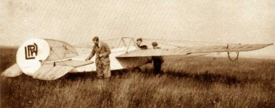
In 1922 John Leeming started to design his fifth glider, which became the LPW Glider, as the cheapest possible way to get airborne, but even the cost of materials worried him. He knew that Avro had made 8,340 Avro 504K trainers, and many were then stored but unwanted.
Leeming approached Avro to seek scrap materials, and met Clement Wood of the Sales staff, who turned out to be a kindred spirit. They raided the “scrap pile” and probably got major components needing minor repairs. The most costly items were two bicycle wheels that cost full price.
The LPW Glider was built by John Leeming, Tom Prince, and Clement Wood who later formed the Lancashire Aero Club.
The original was converted from an Avro 504K trainer.
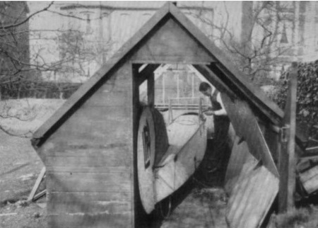
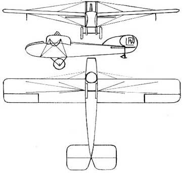
Leeming cut off the nose and front cockpit, and faired it in. Wing panels were fixed to the top fuselage longerons and braced from upper pylons and the bottom of the fuselage.
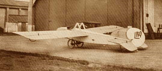
The thin wings had two spars, so the lift bracing wires also added torsional stiffness; a picture shows that the outer wings twisted nose-up.
The result was an enclosed body rather than the later open framework. But gliding performance wouldn’t be too good, with a large fuselage and so many bracing wires. The glider flew on 24 May 1924 from Alexandra Park Aerodrome in Manchester being towed into the air by a car. Based on simple assumptions, it probably stalled at 25 knots, had minimum sink of 3 knots at 30 knots, and maximum glide 12 to 1.
Flying took place at Alexandra Park aerodrome, in the middle of Manchester, starting 24 May 1924, car towing, having trouble with the long grass.
Rope length was quoted as 200 feet, so straight hops were all that was possible. Several pilots flew on many occasions. Leeming crashed the LPW in September 1924 when flying for press photographers on a windier day than usual. Struggling to fly level in the gusts, he didn’t notice how high he had reached so quickly.
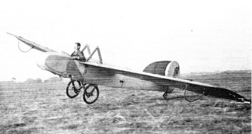
The driver looked back and saw the glider above, probably feared that the rope would fall on him, stopped the car and ran away. The glider stalled, and didn’t recover, probably through the wind gradient; Leeming wasn’t hurt, but the glider was badly smashed.
The wreck was rebuilt, fitted with an engine, and used for taxiing practice for new recruits, but it never flew. Leeming says that it was too heavy, probably too nose-heavy.
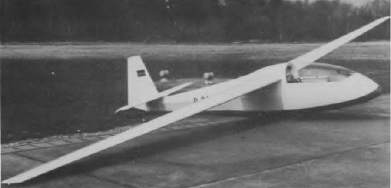
Lommatzsch FES 530 / II Lehrmeister

The “Lehrmeister” is a 1953 wooden training soaring glider that was in use for basic and advanced
training. Some parts were made from polyester.
Length : 26.083 ft / 7.95 m
Height : 6.89 ft / 2.1 m
Wingspan : 55.774 ft / 17.0 m
Aspect ratio : 15.2
Wing area : 204.516 sq.ft / 19.0 sq.m
Max take off weight : 1102.5 lb / 500.0 kg
Weight empty : 661.5 lb / 300.0 kg
Max. weight carried : 441.0 lb / 200.0 kg
Max. speed : 108 kts / 200 km/h
Landing speed : 31 kts / 58 km/h
Cruising speed : 39 kts / 72 km/h
Wing load : 5.33 lb/sq.ft / 26.0 kg/sq.m
Glide ratio : 28.0
Crew : 2