Jim Maupin Ltd
1996: 24201 Rowel Ct, Tehachapi, CA 93561, USA.
1998: 24201 Rowel Court, PO Box 4300-37, CA 93561, USA
Builder of light gliders.
Jim Maupin Ltd
1996: 24201 Rowel Ct, Tehachapi, CA 93561, USA.
1998: 24201 Rowel Court, PO Box 4300-37, CA 93561, USA
Builder of light gliders.
Avions Mauboussin
After his separation from Peyret, Mauboussin redesignated his designs in a sequence that derives the Peyret-Mauboussin designations. The PM XI and PM XII were redesignated as M.111 and M.112 (although still reported as ‘M.11’ and ‘M.12’ in the early 1930s).
Pierre Mauboussin established design office and factory at Puteaux, Seine, France, developing Corsair light aircraft which was built as Corsair 120 and Corsair Minor.
Production aircraft designations were in a more typically French pattern. The production PM XII/M.12 became the M.120 with major developments following as M.121-M.129. Inititially, M.120 developments received suffix numbers based on their year of original (eg: the M.120/37 project of 1937 which led to the production M.123 Corsaire).
Production license for all Mauboussin aircraft acquired by Societe des Etablissements Fouga in 1936. Mauboussin 123, development of Corsair, built 1937-1938, and as M.129 1947-1948.
According to Flight (30 Sept 1943), after the Armistice the Mauboussin plant was engaged in glider production.
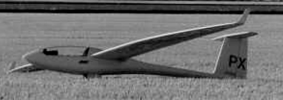
Built by Peter Masak, the Scimitar is a 15 m racing class sailplane which matches an advanced Discus planform wing with electronic boundary layer control married to a Schempp-Hirth Ventus fuselage. The Scimitar II is a Standard Class sailplane developed form the Scimitar I.
Wing span: 15m / 49.2ft
Wing area: 10.5 sq.m / 113 sq.ft
Empty Weight: 272 kg / 600 lb
Payload: 238 kg /525 lb
Gross Weight: 510 kg / 1125 lb
Water Ballast: 113 kg /250 lb
L/DMax: 43 111 kph / 60 kt / 69 mph
Seats: 1
No. Built: 1
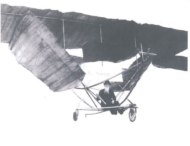
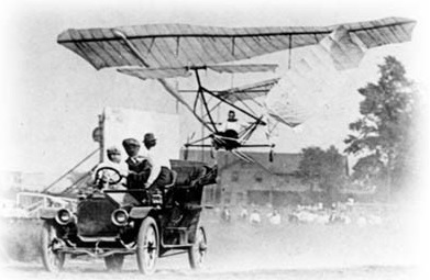
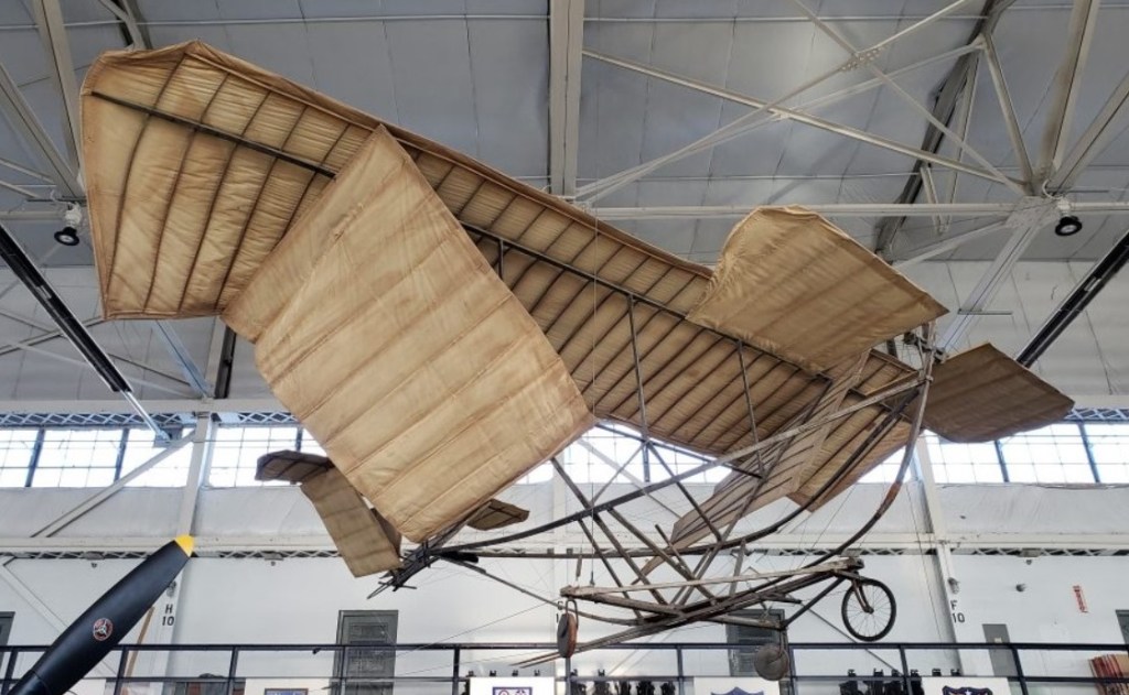
This monoplane was the first of its type in the world, and made many successful flights when towed by a horse or a Ford car. The inventor knew his aerodynamics, and his plane embodied principles of safety that have been generally adopted in plane construction.
On January 12, 1909, snow covered the fields back of the Martin farm, Canton, Ohio, and the device was hauled out and taken to the top of a hill. Old Billy, the farm horse, was hitched to the front of the plane by a long rope. Mr. Martin took his seat in the plane, son George whistled to Billy. The horse started down the hill pulling the plane behind him. It rose from the ground, reached a height of 25 feet and traveled 200 feet before the horse slackened its pace and the plane settled gently back to earth.
Mrs. Martin then took her seat in the plane and made several successful flights, being the first woman ever to fly in a heavier than air machine. Another son, Charles C. Martin, also went up and said that it came down like a feather. When he shut his eyes, he didn’t know when it struck snow.
Mr. Martin’s experiments had been kept secret, but the trial flights could not be hidden. Neighbors flocked to the field to see for the first time in their lives a human being sustained in the air by a heavier than air machine. Cousin Glenn L. Martin had not yet built the first plane in California.
A photographer came out to take pictures of the flights but became so excited that he failed to operate his photographic apparatus properly and all the plates were ruined!
During successive days more than 100 flights were made. All the members of the family, including the pet dog enjoyed the novel experience. One day one of the sled runners struck a bare spot on the ground and swerved the plane against a fence, damaging it slightly. The flights were suspended for a time.
William H. Martin had his eye on more than the local scene and wanted to get his plane demonstrated in the East, but was handicapped by lack of funds. William A. Hoberdier, who, with his brother, L.A. Hoberdier operated Lyric Amusement Co. of Canton, is credited with having helped finance trips to New York in the Spring of 1909.
Another milestone was established September 21, 1909, when Mr. Martin’s eight-year-old granddaughter, Blanche Martin, made several solo flights in the machine, thus demonstrating its safety. Her hops were 75 feet in length, and it was the first time a child of such age had ever taken to the air in a “heavier than air” machine.
Mr. Martin sought to obtain a motor for his plane and wrote to F.S. Lahm, noted Canton balloonist, then living in Paris. In a letter from Paris, dated March 15, 1909, Mr. Lahm told him that the only successful motor then on the market was exorbitantly priced and advised that a smaller one was to be produced soon. Some used motors were obtainable, but were unreliable.
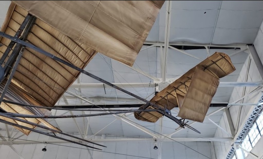
Twenty years after the plane was built, patented and successfully flown, Mr. Martin offered it to the Smithsonian Institution. After long and careful investigation the Smithsonian institution accepted it as being the first plane of its type, and put it on display next to Lindbergh’s “Spirit of St. Louis.”
In 1936 Dennis R. Smith, when returning from a marble tournament, stopped in at the Smithsonian Institution and saw the Martin plane on display beside Lindbergh’s Spirit of St. Louis.
When he returned to Canton he met William H. Martin on the street and reported seeing his plane at the Smithsonian. Mr. Martin, then an old man of 81, with long white whiskers, and gentle and quiet spoken in manner, had the happiest moment of his life when he knew that his contributions to air pioneering had been memorialized by the preservation of his machine. His patent had run out in 1926, and he took additional satisfaction in knowing that the invention which he had patented was free for the use of all mankind.
When Harry Renkert organized the Canton Aviation Co. in 1938, and acquired the land for the airport, he named it Martin Field in honor of William H. Martin, whose farm adjoined the field.
The McKinley Presidential Library & Museum has graciously put the Martin Glider on indefinite loan to MAPS Air Museum as of February 16, 2002.

With the experience gained from the conversion of Motor Cadet PFA.1385, P.J.Martin began building a definitive motor glider which he call the Martin Slug.
It was given the PFA number 1388 and was to be powered by a VW engine.

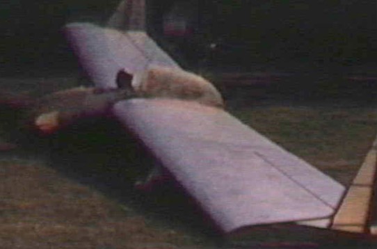
The first of James J Marske’s Monarch hang gliders was begun in 1973 and made its first flight on the 4 July 1974. Plans and kit were then made available to homebuilders and two years later more than 70 gliders were already in the course of construction, principally in the United States.
Aimed more at open-cockpit enthusiasts than at soaring pilots, it offers good slow-flight performance, allowing weak thermals to be exploited. The pilot is seated in the open behind a fairing, even with the leading edge and below the high-mounted wing, the latter slightly swept forward and reinforced by two struts. The flight controls are of the conventional 3-axis type, the rudder pedals operating the rudder and the stick controlling the ailerons and elevators.
The Monarch carries a full complement of controls including airbrakes for glide-path control. The nose fairing improves aerodynamics, provides crash protection, and it looks nice. The overhead control stick also acts as a crash barrier for the face in case of a collision with wires or fences. The Monarch can be flown at sub-stall speeds. without loss of control, which may be as low as 12 mph. Normal thermaling speed is 25 to 28 mph with an accompanying sink rate of slightly less than three ft./sec. Cruising speed at two m./sink rate is 53 mph.
Construction of the Monarch is nearly all plastic with some wood and steel. Steel provides stiffness and durability in control drives and fittings. Wood used in cap strips over the foam ribs, for trailing edges, and control-surfaces spars. The fiberglass fuselage is molded in two halves and bonded together after the control system and fittings are installed. The fiberglass nose, bucket seat, and instrument panel are bonded on and complete the fuselage. The wing leading-edge and spar are pre-shaped in molds and provide the wing’s strength. The aft section of the wing and fin are covered with light weight dacron and doped for airtightness.
The Monarch may be transported to and from the soaring site with the fuselage carried in the back of a station wagon and the wings in a cradle on the rooftop. Assembly time is about 15 minutes.
An attempt was made in 1976 to motorise the Monarch using a McCulloch 12 hp engine installed behind the cockpit, driving a 0.6 m propeller. As this small diameter did not allow adequate performance to be achieved, the experiment was not pursued. The Monarch is easily trailerable; it is sold as a kit like the Pioneer. It allows narrow thermals to be exploited with complete safety thanks to its low stall speed (39 km/h).
The Monarch B appeared in 1976, turning into an ultralight through the expedient of a McCulloch Mc101 12hp engine, installed behind the pilot’s seat and driving a twin ¬bladed pusher propeller of 25 inch (0.64 m) diameter, under the spar joining the ‘tail’ to the wing. Like its predecessor the type B used a skid underneath the fuselage as its landing gear.
However it became apparent that this model was under powered and Jim Marske sells plans and kits for the Monarch C fitted with a tricycle undercarriage, or alter¬natively a single main wheel tailwheel arrangement. The C model is intended for engines up to 20 hp output. By comparison to the type C, the latest variation tried by Jim Marske with 20hp instead of 12 gives a maximum straight and level speed of 87 mph (140 kph) and cruises at 76mph (122kph).
Monarch C; a single seat single engined high wing mono¬plane with conventional three axis control. Wing has 3° at the quarter-chord line swept forward leading and trailing edges, and tapering chord; no tail. Wing braced from below by single steel struts; wing profile NACA 43012R and NACA 43112; double surface. There is a glassfibre front spar and a moulded glassfibre D leading edge, and wood and foam plastics ribs between the front spar and the wooden rear spar and trailing edge, the wing aft of the front spar being fabric covered.
The fuselage is a simple minimal pod-and-boom type structure of laminated glassfibre, moulded in two halves and joined at the centreline; the forward section carries the pilot seated in the open without a transparent canopy, with a nose fairing over the instrument panel, and the rear boom section also forms the integral fin leading edge. There is a towing hook on each side of the nose fairing. The fin and rudder extend below as well as above the wing level, the fin having a glassfibre leading edge and the rudder a wooden trailing edge; both have foam ribs and fabric covering.
Pitch control by elevators on inboard trailing edges; yaw control by fin mounted rudder; roll control by ailerons and spoilers; control inputs through stick for pitch/roll and pedals for yaw. Both the ailerons in the conventional outboard positions and the elevators inboard of them have single Sitka spruce spars with foam plastics ribs, and there is a fixed tab in each elevator; all the control surfaces are Dacron-covered and there is an aluminium spoiler above each wing.
Undercarriage has three wheels in tricycle formation (Two wheels in tandem optional) with additional tailwheel. Steel spring suspension on nose¬wheel and glass ribre suspension on main wheels. Push right go right nosewheel steer¬ing connected to yaw control. Glass fibre fuselage, partially enclosed. En¬gine mounted above wing driving pusher propeller.
Plans and kits were available to the homebuilder for the Monarch C ultralight motorglider. Power is supplied by a 12-hp McCulloch engine located behind the pilot’s seat; however, engines up to 20 hp can be used. The high wing makes use of a wooden rear spar with woodand-foam ribs. Fiberglass covers the leading edge, and the remainder of the wing is covered with fabric. Despite its fragile appearance, the Monarch C is stressed to +8Gs and -4Gs. The fuselage pod is molded in two pieces then joined at the centerline; there are no horizontal
tail surfaces. A single landing wheel is beneath the pilot.
The Monarch C is still transportable by road trailer and the work involved in rigging the wings and control runs does not exceed 15 min for two people. The price of the plans was $90 in 1982.
The D model has longer span ailerons than the C, and the E has relocated spoilers and a larger rudder. In the later 18 kW/ 24 bhp model (original had a 12 bhp engine), the wing is moved slightly backward for balance, and fuel is carried in the leading edge. There have been a number of other modifications including replacement of the original overhead stick with a conventrional stick and ailerons and rudder increased in size to improve low-speed handling.
According to the designer, the construction of a Monarch requires some 200 h of work using one of his kits and from 400 h using purely the plans. The construction of this high quality machine makes extensive use of layers of glass fibre with epoxy for leading edges, wing support struts, fuselage, nose fairing, seat, instrument panel and spoilers. The wing ribs and the tail surfaces are cut from polyurethene foam and plywood. Apart from the fuselage, the surfaces are covered in Dacron.
Monarch
Wing span: 12.80 m /42ft
Length: 3.71 m
Wing area: 17.19 sq.m /185sq.ft
Airfoil: NACA 43012 – 75
Aspect ratio: 9.5
Empty weight: 100 kg / 220lb
Max. weight: 204 kg / 450lb
Payload: 104kg / 230lb
Wing Load: 11.72 kg/sq.m / 2.43 lb/sq.ft
Stall speed: 39 km/h
L/D Max: 19 64 kph / 35 kt / 45 mph
Min Sink: 0.85 m/s / 2.7 fps / 1.60 kt
Sink rate: 0.82 m/s
Airfoil: Modified NACA 43012
Seats: 1
Monarch
Wingspan: 36 ft.
Aspect Ratio: 8.3
Wing Area: 155 sq./ft.
Airfoil: NASA 43112
Monarch C
Span: 42 ft 0 in
Length: 11 ft 6 in
Wing area: 185.0 sqft
Aspect ratio: 9.5
Empty weight: 220 lb
Max weight: 450 lb
Max speed: 70 mph (smooth air)
Min sinking speed: 2.70 ft/sec at 30 mph
Best glide ratio: 19:1 at 40 mph
Monarch C
Engine: McCulloch Mc 101, 12 hp at 9000 rpm.
Prop¬eller diameter 25 inch, 0.64m.
Power per unit area 0.06 hp/sq.ft, 0.7 hp/sq.m.
Fuel capacity 2.0 US gal, 1.7 Imp gal, 7.5 litre.
Length overall 11.4 ft, 3.45 m.
Height overall 7.9ft, 2.36m.
Wing span 42.0ft, 12.80m.
Mean chord 4.4ft, 1.32m.
Dihedral 2 deg.
Sweepback –3 deg at trailing edge.
Total wing area 185 sq.ft, 17.2 sq.m.
Wing aspect ratio 9.5/1.
Empty weight 250 lb, 113kg.
Max take off weight 475 lb, 215 kg.
Payload 225 lb, 102 kg .
Max wing loading 2.56 lb/sq.ft, 16.8 kg/sq.m.
Max power loading 39.6 lb/hp, 17.9 kg/hp.
Load factors; +8.0, NC ultimate.
Max level speed 78 mph, 126 kph.
Max cruising speed 68 mph, 109 kph.
Economic cruising speed 42 mph, 68 kph.
Stalling speed 27 mph, 43 kph.
Max climb rate at sea level 460 ft/min, 2.3 m/s.
Min sink rate 220 ft/min at 32 mph, 1.1 m/s at 51 kph.
Best glide ratio with power off 15/1 at 42 mph, 68 kph.
Take off distance 235 ft, 72 m.
Landing distance 150 ft, 45 m.
Range at average cruising speed 60 mile, 97 km.
Monarch F
Speed max: 70 mph.
Cruise: 45 mph.
Stall: 26 mph.
Aspect ratio: 9.5:1.
L/D: 20:1.
Min sink: 162 fpm.
Landing dist: 90 ft.
Weight empty: 220 lbs.
Gross: 450 lbs.
Height: 5 ft.
Length: 12.5 ft.
Wing span: 42.6 ft.
Wing area: 186 sq.ft.
Seats: 1.
Landing gear: single wheel.
Monarch G
Span – 42.6 ft
Area -163 sq ft
Aspect ratio -11.1
Empty weight -180-200 lbs
Pilot Weight -120-220 lbs
Flying weight -300-420 lbs
Wing loading 1.8 -2.6 psf
Glide Ratio – 22 @36 mph
Min. sink rate – 138 fpm @ 30 mph
A model with a wing stretched to 15 m all glass construction and a more streamlined fuselage, the Pioneer III is to be put into production. With a maximum glide ratio of about 42, and with a low stall speed, this glider should combine high speed performance and safety at low speed, at a lower cost.
Pioneer III
L/D 42:1
Min sink 100 ft per min
Vne 150 mph
Vb 130
Vs (stall) 38
Empty wieght of 345 lbs
Aspect ratio: 16.8

The lighter Pioneer II-A was developed for homebuilt construction, with a glass-fibre fuselage and separate ailerons and flaps. Redesigned from the Pioneer IA, the wing has, had the span reduced to 13 m so it could be built in a standard 20 ft. garage. Upper-and-lower surface airbrakes are used for glidepath control. Because a tailless sailplane has a narrow centre of gravity range, an adjustable seat was positioned above the fixed landing wheel, which itself is on the centre of gravity. The pilot simply moves the seat until his/her own weight balances the ship on the wheel. It made its first flight in 1972. The following model, Pioneer II-B, had a longer canopy and a section based on the NACA 33012/33010 allowing an improvement in low speed performance. The Pioneer II-C included a few simplifications and lightening of the fuselage structure.
Model Pioneer IID, went into production, is distinguished primarily by its swept fin and modified wing leading edge. Its maximum glide ratio is 35, despite a low aspect ratio (less than 13). Stall speed is below 60 km/h, and the glider is stall resistant and completely spin proof. It was sold as a kit to amateur builders, assembly requiring approximately 600 hours.
At least one Pioneer II has been modified by adding tip extensions to increase the wingspan to 14.0 m.
A P2 that was modified by Jay Johnson in McCook Nebraska had the conventional rudder replaced with spoilers operated by the pedals. A fixed fin replaced the rudder. Slow, tight turns required almost no spoiler and the combined effect of ailerons and spoilers produced a very fast roll rate of around 3 seconds in a 45 to 45 degree roll.
Pioneer II
Wing span: 12.98m /42.64ft
Wing area: 13.8sq.m /144sq.ft
Aspect ratio: 12.6
Airfoil: Modified NACA 33012/33010
Empty Weight: 172kg /380lb
Payload: 113kg /250lb
Gross Weight: 285kg /630lb
L/D Max: 35 97 kph / 52 kt / 60 mph
Min Sink: 0.7 m/s / 2.26 fps / 1.34 kt
Wing Load: 20.65kg/sq.m /4.4lb/sq.ft
Seats: 1
No. Built: 15
Pioneer IID
Top speed: 130 mph
Cruise: 95 mph
Stall: 35 mph / 57 km/h
Aspect ratio: 12.59-1
L/D / Glide ratio: 1:35 at 97 km/h
Min sink: 126 fpm / 0.70 m/s
Landing dist: 170 ft
Empty weight: 350 lb / 159 kg
Gross weight: 600 lb / 295 kg
Height: 5 ft
Length: 12.5 ft / 3.81 m
Wing span: 42.6 ft / 12.98 m
Wing area: 144 sq.ft / 13.38 sq.m
Airfoil: NACA 33012 – 75
Seats: 1
Landing gear: single wheel
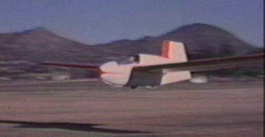
Based on experiments with the XM-1 glider, Jim Marske, aided by Bill Daniels, flew the Pioneer I in 1968. The Pioneer is the second Marske tailless sailplane to fly. This glider was distinguished from the earlier one by a higher aspect-ratio wing of trapezoidal planform, with a slight forward sweep. The Pioneer I used a NACA 23112 modified by raising the trailing edge. Roll control was by spoilers, but the machine used a more conventional fuselage-mounted rudder for yaw control. This was later modified after the first fight tests by adding a fixed portion in order to improve its effectiveness. The span of the glider was also increased, justifiying a change of designation to Pioneer I-A.
Both the XM-l and the Pioneer I were low wing loading gliders, designed as proof-of-concept designs incorporating the maximum safety of the test pilot through very low take-off and landing speeds.
The controls were elevators hinged to the inboard trailing edge of the wing, conventional rudder/fin mounted on the centerline (originally, an all-moving rudder without fin), and spoilers for roll control.
The initial flight tests were conucted at the El Mirage dry lake to make long auto tows and long straight glides without worrying about obstacles. In March of 1968, in eight flights in a day it progressed from low, straight glides to 1000-foot altitudes and shallow S-turns without encountering anything but minor problems. One problem was a slower roll rate than hoped for, and the other was that the all moving rudder would oscillate at about 1Hz when free. The rudder could, however, be controlled easily so long as the pilot kept his feet on the pedals. Pitch control proved to be docile. The most apparent thing was the lack of inertia, about the pitch axis, allowing the pitch changes to be made almost instantly without any tendency to overshoot the new attitude.
The next day provided the first opportunity to try the Pioneer at Soaring. An auto tow to 1500 feet it into a small thermal. The climb took it to 11,500 feet ASL, (9500 above terrain).
Trying a gentle stall straight ahead, the stick reached the rear stop before a break occurred. With the stick held back, the ship flew straight ahead with no tendency to drop a wing. A pronounced low frequency buffet came from somewhere to the rear. Trying again with the nose well above the horizon resulted in a gentle break with surprisingly little loss of altitude, again no wing drop. Stalls from turns were no less docile. The ship maintained its bank angle and recovered flying sped immediately. It was becoming clear that while the machine could be momentarily stalled, it could not be held in a stalled condition.
This is apparently due to the fact that the elevator is part of the wing and is affected by the flow separation that starts at the trailing edge as the glider approaches a stall. As this flow becomes turbulent and separates, the up elevator authority is sharply limited. It is therefore not possible to increase the angle of attack to the stall. The effect is to limit the minimum airspeed to a safe value.
An objection is sometimes raised to this saying that if the up elevator authority is limited to prevent a stall, the landing speed will be too high. However, with the flying wing, during the flare before touchdown, the airflow under the wing produces a low-pressure area under the elevator. This is due to the venturi-like shape of the area confined by the under surface of the wing with a raised elevator and the ground. This low-pressure area occurs only when flying in ground effect and greatly assists the flare so the flying wing can be landed a very slow airspeed.
It was stable about all three axes, that it responded logically to all control inputs, that it would not spin however provoked, and that it retained its pitch stability on speed runs to100 mph. If the stick were released in straight and level flight at the trimmed airspeed, the ship would continue straight ahead for up to a minute, then gently enter a spiral. If the controls were released at a speed other than the trimmed speed, the ship would gently oscillate in pitch about the trimmed speed, with a 17-second period. This would damp out in three or four oscillations in smooth air. The oscillation was never noticed unless the stick was free. If the ship were placed in approximately a 30-degree yaw angle relative to the direction of flight and the controls released, the nose would swing back into line within three seconds, overshooting slightly.
A few points were not to liking. For one thing, while the roll spoilers’ alone produced coordinated turns at 60 kt, they tended to produce skidding turns above that speed. The effect was gentle, but noticeable, and required rudder input to keep the yaw string centered. It is odd to need opposite rudder to make a coordinated roll into a turn at high speed. In slow turns it showed the normal glider tendency to overbank and opposite spoiler was necessary to stop it. This was disturbing because it resulted in loss of lift when it was needed most. In spite of circling in thermals with one spoiler open, the ship seemed to climb extremely well.
On the plus side it was found that the ship was taking less of a pounding during high speed runs than might be expected for a light wing loading machine flying in strong desert turbulence. The panel-mounted accelerometer showed a maximum of +2g, -1/2g for the 100mph runs, although pitch attitude changes were noted in turbulence. It seemed that the nose went up in down gusts, and up in down gusts, reducing the wing’s angle of attack relative to the local flow quickly enough to prevent the machine from absorbing the load. This is no doubt due to the low moment of inertia about the pitch axes. On several occasions, while flying in formation with other sailplanes, they broke off saying it was too turbulent to be going so fast.
On the slow end of the airspeed envelope, the Pioneer proved to be a surprising performer. The Pioneer 1 would fly with the airspeed needle rested on the peg and refusing to indicateas the speed was below the instrument’s threshold. This slow flight ability proved a tremendous asset in small, weak thermals, where it allowed extremely small diameter turns to be made.
From May to August of 1968, the Pioneer was modified to correct some of problems found in the original configuration. The opportunity was taken to lengthen the wings from 40 to 46 feet. This brought the wing area to 192-sq. ft. Considerable effort was made to reduce the moment of inertia about all axes. This resulted in an overall weight reduction of 10 pounds to 430 empty even with the longer wings. A new airspeed was installed that would indicate down to 10 knots. As a result of these modifications, the ship is now called the Pioneer IA.
First flight tests of the modified version began in August 1968. The handling qualities were generally the same as the 40-foot span Pioneer, with the exception that the rudder was stable and surprisingly effective considering the short moment arm. However, the roll rate was still disappointingly slow even though the spoilers had been moved forward and outboard.
It was decided that the roll rate might be improved if air were allowed to escape (in a “puff”) from within the wing as the spoiler was opened. It was thought this would “trip” the flow quicker. They used gaskets to seal the spoiler box completely when it was closed. This small modification almost doubled the roll rate, cutting the time required to perform a coordinated roll from a 45-degree turn in one direction to a coordinated 45-degree turn the other way from 9 seconds to just under 5 seconds, measured at an airspeed of 50 knots.
The performance gain with the longer wings was quite noticeable. Flight comparisons seemed to suggest that it achieved just under 30:1 L/D at 50 Kts combined with very good climb performance. With the new ASI, the minimum airspeed was found to be an indicated 28 knots. At this speed the sink rate was not significantly more than at the minimum sink speed of 40 knots. Soaring flight has been achieved on all except one attempt, with an average time per flight of just less than two hours. Most of these flights were made from auto tows.
The over banking tendency noted in the early tests seemed to be less noticeable in the Pioneer IA. Glide path control on the Pioneer 1A was provided by dive brake/flaps hinged at the mid chord point on the underside of the wing. These acted to increase drag and to increase the coefficient of lift. At the speeds used for approach and landing, trim changes are negligible. At higher speeds there was a noticeable nose-down pitching moment.
The problem with the P1A is that the rudder and roll spoiler response axes didn’t meet at anything close to 90 degrees. In fact, they were almost parallel. In effect, the P1A had two rudder systems and no ailerons.
The Pioneer 1A flew on for several more years. After moving to Colorado in 1969, the P1A flew on several long cross country flights. The ability to use very weak lift and, if that failed, land almost anywhere helped. On one flight, it reached 32,000′ in the Pikes Peak wave. In this time almost twenty pilots to fly the P1A.
Pioneer I
Wing span: 40 ft
Pioneer IA
Wing span: 46 ft
Wing area: 192 sq. ft
Empty weight: 430 lb
Aspect ratio: 10.8
Fuselage length: 12.5 ft
Wing loading: 3.5 lb/sq.ft
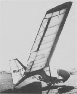
The XM-1 was designed and constructed as a research and development sailplane. This sailplane is intended to be the first of a series to discover the most practical soarer for the weekend flyer. The plank layout was chosen for simplicity of design, very good performance for its size, forgiving flight characteristics, being stall and spin proof and light in weight making the ship easy to handle on the ground.
Flaps have been installed instead of the usual spoilers to allow a quick take-off on auto or winch tow and they provide a low landing speed. Another advantage of flaps is that the top of the wing is kept clean and eliminates the possibility of water running into the wing if caught out in the rain. Another feature is the use of C.G. tow hooks. They have no adverse affect on the aircraft at any time on any type of tow. Only the wings are removed from the pod and are joined in the usual manner. The wing has a span of 38 feet, a constant chord of 51 inches and an aspect ratio of 9. Since the aircraft was to have a moderately low wing loading a 14% reflex airfoil was chosen for good high-speed performance. The XM-1 used a Faubel airfoil section with a relative thickness of 14 %.
In order to keep all lines as clean as possible for efficiency, molded fiberglass is used wherever possible in the structure. The main wing spars are of laminated spruce tapered in thickness from root to tip to distribute flight loads evenly. The main wing ribs are of standard truss type construction while the nose ribs were sawn from 1/4-inch marine plywood. A rear spar is used mainly for fastening fittings, eleven hinges and to transmit drag loads to the fiberglass skin.
The elevons are controlled by pushrods throughout while the rudders are cable actuated. Molded fiberglass covers the leading edge D tube and the first five root rib panels aft of the main spar to carry the drag loads. This consists of two laminations of glass cloth secured to the wing with epoxy resin. The basic structure of the XM-I as Et was being constructed. The fiberglass fuselage shell is just as it came from the mold. Construction of the fins are basically a spruce and plywood frame covered with fabric. During flight tests in 1957, smaller and heavier fiberglass covered fins were used with drag flaps but were discarded clue to their ineffectiveness. All fiberglass sheets were formed on a smooth flat metal sheet that was given a heavy coat of paste wax. One side of the fiberglass sheet thus formed is rough while the surface which was against the metal surface is smooth as glass. The smooth surface is used as the outside finish. Then securing fiberglass to fiberglass, or fiberglass to wood, the surfaces that will come in contact with one another must be made rough in order to give the resin something to cling to. So far, I have found epoxy resin to be the best gluing agent for fiberglass but you must work fast before the resin hardens. The leading edge fiberglass sheets were formed in a jig because a flat sheet of two laminations cannot be drawn around the leading edge.
The fiberglass shell of the fuselage was formed over a built up plaster mold. This shell consists of three to four layers of glass cloth, four layers being used where higher strength is required. Sanding fiberglass by hand can be an exhausting job so a belt sander was rented. A tubular steel frame was welded together to fit into the fiberglass shell. This frame carries all flight, towing and landing loads imposed upon the aircraft.
To secure the frame to the shell, all tubing that was to come in contact with the shell was wrapped with strips of glass cloth and given a coat of resin. After it hardened it was sanded down and fitted to the shell. Additional strips of glass cloth were then given a coat of resin and stretched between the shell and the wrapped tubing. When this had hardened it was sanded down and given another coat of resin to give it a smooth finish.
The remainder of the shell was strengthened by the addition of two fiberglass bulkheads and reinforcements in the nose. In the cockpit a control wheel is used rather than the conventional stick. The rudder pedals now operate in a conventional manner made possible by the highly differential bellcranks, which allow only one rudder to swing out at a time.
Jim Marskes XM-1 glider made its first flight in 1957. Test flights began with a few soaring routine ground slides were made at speeds up to 30 mph to see how it would handle. Aileron control was very good and it was also possible to balance the glider on its wheel by the use of the elevons. The next tow was to be a slow acceleration up to 40 mph to see if it would fly. The tow started off well, lateral control was good but the rudders were, a bit sluggish. At 30 mph the control wheel was brought back and the ship responded with the nose coming up to take-off position. At 40 she was airborne and leveled off before trying a few gentle pull-ups to get the feel of the elevators. All controls responded smoothly and firmly. Upon release of the towline the sailplane suddenly dropped as if stalled out. Applying full backpressure did not remedy the situation and the resulting drop to the ground shook both glider and pilot. When the towline was released it was flying only a few mph above the stalling speed. With the C.G. tow hooks located considerably below the center of gravity there was a tendency for the tension of the towline to hold or bring the nose up. Also, by applying full backpressure suddenly is much the same as raising flaps on an airplane just before touchdown.
The following weekend flight called for 50 mph and a free flight glide. Release was to be made only a few feet off the ground so if it would drop it would not have far to go. Once again airborne it rose very quickly from the ground due to the kiting affect of the low tow hooks. On release, at about 12 feet it chased the tow car down the runway and was gaining on it. Leveling off, the airspeed dropped from 41 to 4·2 mph. This flight revealed a lack of directional control causing the craft, to rotate about its vertical axis as other plank designs have experienced.
Modifications were not completed until September of 1959. The first change to be made was the relocation of the tow hooks to eliminate the kiting affect. This was accomplished by raising them approximately 5″ to bring them closer to the center of gravity. The previous lack of directional stability had required the pilot to be on his toes all the time. To rectify this situation the fuselage length was increased by 9 inches and the hood given a dorsal fin look. A new and larger set of fins were constructed which replaced the drag flaps with differential rudders of double the previous area. Also, the independently operating rudder pedals gave way in favor of the conventional setup.
By September all modifications were completed and after assembly of the craft at the airfield and several ground slides later it became apparent that there was a marked improvement in response to the controls. On this next tow control again was firm and responsive. The take-off was very smooth with no corrective force of any kind necessary. The kiting and yawing affect had completely disappeared and the ship had become as stable as any sailplane. Each succeeding tow took me a little bit higher and became routine and uneventful. At 50 feet and dropping full flaps they behaved exactly as they were designed to. From this time on all take-offs and landings were made with full flaps, resulting in shorter take-offs and slower landing speeds. The flaps produce no buffeting whatsoever and are quite effective.
Using a 450 foot towline take-off was made with full flaps, requiring a 100 foot run: into the 5 mph head wind. Going up no lateral or directional control was required and the ASI indicated 55 mph all the way. Release was made at 350′ and was very smooth, they’re being no tendency to pitch up.
On this prototype, numerous configurations were tested including wingtip fins, central fin, spoilers, flaperons. Based on these experiments, Jim Marske, aided by Bill Daniels, flew the Pioneer I in 1968.
