Oškinis BrO-21 Vyturys

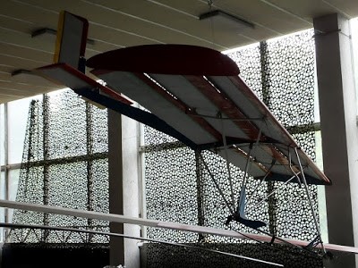
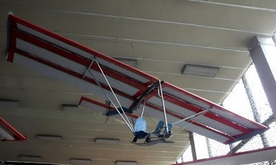
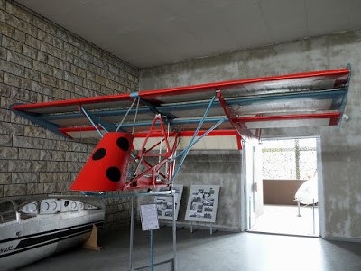
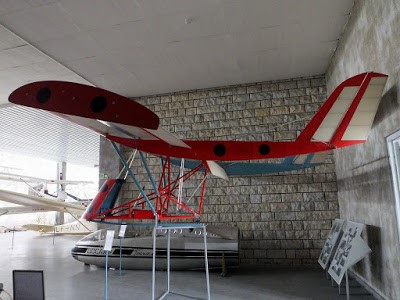
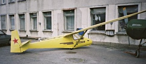
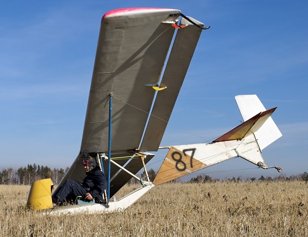
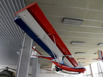
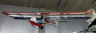
The BrO-21 Vyturys training glider prototype was built in Kuibyshev with the help of Aviation Factory engineers and Aviation Institute students.

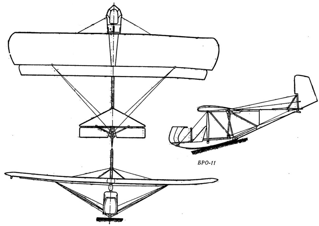
The wing of the of the BRO-21 Vyturys glider consists of four balances and two ailerons. The wings were arranged one after the other with an overlap of 70 mm, forming a 40 mm slit forming an angle of 7 degrees.

The BrO-21 1980 At the beginning of 1980, the construction of the second example of BRO-21 was started in Palanga, the construction of which was completed in Kaunas in 1980. June 20 his trials began.

Polymers and glass cloth were used in the construction. The gap between the spar is filled with epoxy- impregnated foam, covered with glass cloth.

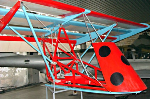
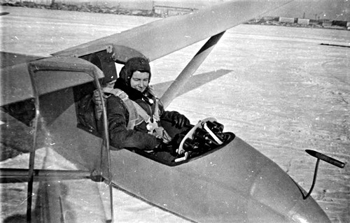
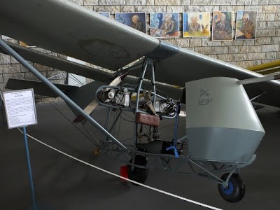
The fuselage consists of a front part (cockpit) and a tail beam. The cabin is made of fiberglass. All cabin sides are covered with microporous rubber edging.

At the bottom, the cabin has 5 rubber “legs” to which it can be attached:
wide fiberglass ski (for winter),
ski with wheel 200 × 80 or 255 × 115 (for summer),
three-wheel chassis (training in landing)
a float that turns the apparatus into a hydraulic dispenser.

The tail beam is made of fiberglass.

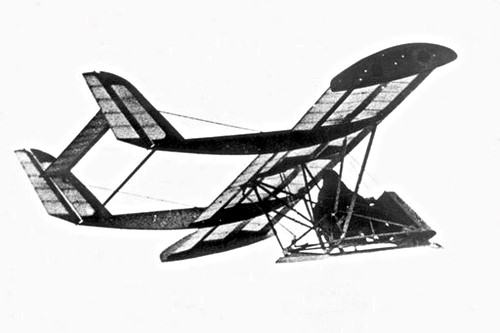
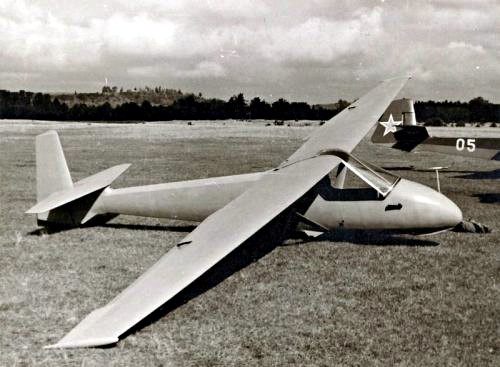
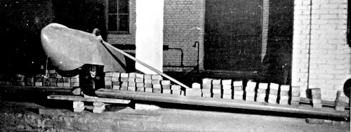
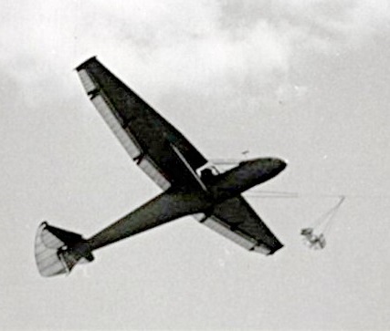
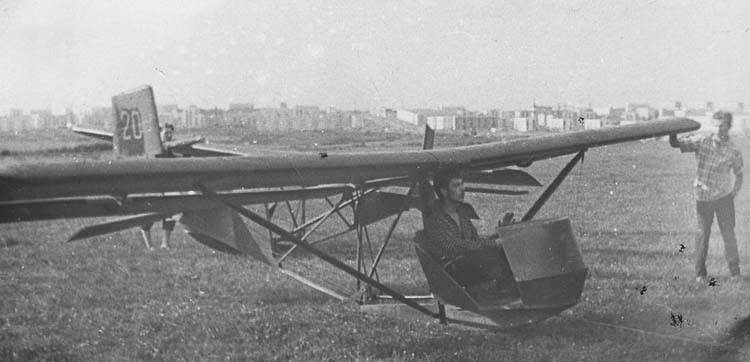
The BRO-21 variant of the glider built in Kuibyshev, was demonstrated in Moscow at a union competition of youth gliding schools. The glider, starting with the shock absorber, showed a great advantage over another classic-designed training glider “Trener” developed by Kuibyshev.
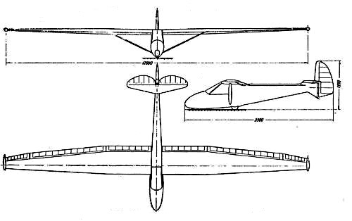
Wingspan: 5.2 m
Length: 7 m
Wing area: 10.5 m²
Empty weight: 84 kg
Take off weight: 160 kg
Pilot weight: up to 76 kg
Maximum speed: 100 km / h
Minimum speed: 35 km / h
Glide ratio: 12
Wing load: 15.2 kg / m²
Seats: 1

Oškinis BrO-18 Boruze

The Oškinis BrO-18 Boružė mini glider was easy to manufacture and easy to handle. With its short wings, Boružė cannot reach high speeds and heights, so it is perfect for training children from 12 years of age. The glider takes off at a speed of 35-40 km / h (3-4 people are enough to take off).

Boružė is an experimental device and probably the smallest glider in the world (wing span – 4.9 m).

Oškinis BrO-12

According to Bronius Oškinis, this glider is designed to be launched with a puller and to be able to reach the thermal. The glider had to be inexpensive, suitable for mass production, so that every gliding club could buy it. Oškinis applied an unprecedented innovation to gliders – hanging flaps and ailerons, which greatly increase the lifting capacity of the wings.

At that time, the Soviet Union’s air construction bureaus focused on the construction of military aircraft, while Lithuanian designers designed gliders because they did not have the opportunity to construct aircraft during the Soviet occupation.

The wings were covered with 1.0-1.5 mm thick plywood, varnished and polished.

Static tests

In order for novice pilots to clearly see the fluctuations in the direction of flight, the glass of the BrO-12 cockpit covered the glider only from the front – the deviation from the straight flight was immediately felt by the pilot blowing in the wind through the open sides. The seat is suitable for flying with a parachute ПНЛ-45.

The BrO-12 prototype was built in 1957. In the workshops of Kaunas Gliding Station. Pulled by a winch, it rose to 400-500 m, and even higher in the event of stronger winds. No other glider was able to take off so much then. In Moscow it was decided to produce BrO-12 series.

The BrO-12 was produced at the Simferopol Aviation Workshop, where during 1959–1961 about 120 units were produced.

In 1959-61, a total of about 20 gliders of this type flew in Lithuania.

In 1959-61, a total of about 20 gliders of this type flew in Lithuania. After the Soviet Union decided to produce metal-gliders, the BrO-12 soon competed with the Czech two-seater Blanik.

BrO-12 at the Lithuanian Aviation Museum

Gallery

Wingspan: 12 m
Wing area: 11.3 m²
Length: 5.9 m
Height: 1.50 m
Empty weight: 160 kg
Takeoff weight: 245 kg
Wing loading: 21.7 kg / m²
Landing speed: 45 km / h
Cruising speed: 60 km / h
Glide ratio: 20
Seats: 1

Oškinis BrO-11 / LAK LAK-2

The Oškinis BrO-11 was a simple, single-seat primary glider designed in the USSR by Bronis Oškinis in the open girder style exemplified by the pre-war SG 38 Schulgleiter. It was more refined, with slotted ailerons and somewhat better-protected seating.

Its high wing, mounted on top of the fuselage girder, was rectangular in plan and built around a single, wooden spar with plywood skin ahead of it, forming a torsion-resistant D-box, and fabric covering behind. The wing was braced to the bottom fuselage beam with a single strut on each side, assisted by drag wires from the nose. Narrow and very high aspect ratio ailerons were hung behind and below the whole trailing edge, leaving a slot between wing and aileron.

The wing of the original production model, named Pionier, Lithuanian for Pioneer (or Pionerius, the plural) had a span of 7.58 m (24 ft 10 in) and an area of 10.5 m2 (113 sq ft). The later Zylė (Tit), alternatively known as the LAK-2, had a slightly larger wing with a span of 7.80 m (25 ft 7 in) and an area of 11.8 m2 (127 sq ft), improving the glide ratio a little.

The forward part of the fuselage was a wooden beam which extended aft to end under the wing trailing edge. At the nose there was a simple, semi-circular enclosure formed from two single-curvature surfaces. This gave the pilot, seated just under the leading edge, some protection from the wind, though not for his upper body or sides. The same beam was attached to the wing with an N-form cross-member and also carried the forward end of the horizontal upper fuselage member. The rear lower member ran upwards to meet the upper one at the tail. In addition, they were interconnected at mid-fuselage by a pair of vertical and diagonal struts. Immediately ahead of the tail the fuselage was fabric covered, though not elsewhere.

Both variants had triangular tailplanes mounted on the upper frame with elevators which were rectangular in plan apart from a cut-out for rudder movement. Their little, triangular fins carried rather angular, quadrilateral rudders.

The fuselages of the Pionier and Zylė differed only in their landing gear. The Pionier landed on the underside of the forward beam but the Zylė had a monowheel semi-recessed into its beam below the forward wing and a short nose skid.

The BrO-11 Pionier first flew in 1954 and was very widely used across the DOSAAF; some 2000 were built between about 1955 and 1960. The date of the first flight of the Zile is not known exactly but was about 1968. Production began by Lietuviškos Aviacinės Konstrukcijos (Lithuanian Aero-Construction, LAK) in mid-1969 and ended in 1979. Production numbers for this variant are not known.

BrO-11M

Gallery

BrO-11 Pionier(ius)
Original design

BrO-11M Zylė
Wingspan: 7.80 m (25 ft 7 in)
Wing area: 11.80 m2 (127.0 sq ft)
Aspect ratio: 5.05
Height: 2.50 m (8 ft 2 in)
Length: 5.16 m (16 ft 11 in)
Empty weight: 65 kg (143 lb)
Max takeoff weight: 125 kg (276 lb)
Stall speed: 31 km/h (19 mph, 17 kn)
Maximum glide ratio: 12
Rate of sink: 1.0 m/s (200 ft/min) minimum
Crew: One

Oškinis, Bronis

Bronis Oškinis was born April 15, 1913 in Barzdai, Šakiai county, Lithuania, in the family of Jonas and Agnieška Oškiniai.

In 1920 the family moved to Kaunas. 1928–1933 Bronis Oškinis studied at Kaunas Higher Technical School (ATM). Interested in aviation, he was one of the Kaunas ATM aviation group, founded on 13 December 1931.

After completing aviation courses, he led the construction of gliders in ATM workshops.

Reconstructed the German training glider RRG-23 “Zoegling” and in August 1932 developed the Lithuanian T-1 (“Technikas-1”) glider. In Pažaislis, this glider was tested by military pilot Gregorius Radvenis. The first flight was performed by B. Oškinis himself.

In 1933, with others, in Nida set up a gliding school. He later constructed the BRO-2 and BRO-3 gliders. He learned to fly not only gliders but also airplanes. In 1936 appointed Deputy Chief of the Zokniai Military Aviation Workshop. He later served as a military pilot in the 3rd Squadron.

Oškinis tested the BRO-4 “Rūta” glider for acrobatic flying in 1937. Jonas Pyragius and Bronius Oškinis participated in the 1937 world meeting in Elmyra (USA), where B. Oškinis flew the LAK glider “Biržietis”, and J. Pyragius – BRO-5 “Rūta”.

In 1938 he graduated from the Lithuanian Military Pilot School and 1938–1940 studied aeronautics at the Technical University of Berlin. He returned to Lithuania in 1940 and was assigned to the workshop of the National Aviation Squadron of the 29th Territorial Rifle Corps in Pivonia (near Ukmergė). 1941–1944 worked in Kaunas aviation workshop in Freda as a production controller, repaired German Junkers Ju-88 and during 1942–1944 studied at Kaunas Vytautas Magnus University.

1944–1945 was arrested and taken to the Podolsk camp, returning to Kaunas 1947, he gave lectures at the State University and continued to develop new gliders. During 1956–1962 was Head of Kaunas Gliding Station, later headed a gliding school in Palanga.

Bronius Oškinis in his design glider BrO-12

Serial production of Bronius Oškinis gliders BRO-9 “Grasshopper”, BRO-11 “Pioneer” and BRO-12 was started in Simferopol aviation workshop. They flew in all aviation sports clubs of the former USSR. 1962 An Experimental Sport Aviation Factory was established in Prienai, where B. Oškinis worked as a designer. Much attention was paid to the development of gliders for young people. They introduced many innovations, using slit wings, slit flaps and ailerons.

Bronius Oškinis developed 25 gliders of various modifications and died on April 7, 1985 in Palanga.

He was awarded by the Lithuanian government and FAI (International Aeronautics Association). The Lithuanian Children’s Aviation School and the street in Palanga are named after him.

Ošk gliders
T-1 (BrO-1) (1932)
T-2 (BrO-2)
BrO-3 “Fluff” (1936)
BrO-4 “Ruth”
BrO-5 “Ruth II” (1938)
BrO-6 “Fluff”
BrO-9 Grasshopper
BrO-10 “Fluff”
BrO-11 Pioneer
BrO-11 M Tit
BrO-12 (1957)
BrO-14
BrO-16 “Pempė” (1973) – water glider
BrO-15 “Raguva”
BrO-17S Bite (1974)
BrO-17V “Antelė” – water glider
BrO-18 Boružė (1975) the smallest glider in the world
Br0-19 “Duck”
BrO-20 “Fluff”
BrO-21 “Vyturys”
BrO-22 “Rūtelė”
BrO-23 “Herons”

Oškinio sport airplanes
BRO-7
BRO-8

Orlican VT-16 Orlik / VT-116 Orlik II / Let VT-16 Orlik

The VT-16 Orlik was designed by Jiri Matejček and is a high-wing monoplane of all-wood construction, except that the skin is stabilized with Umakol high-smoothness polystyrene foam. Its wing has a single spar structure with a forward torsion box; the whole wing is plywood skinned and foam filled, allowing the ribs to be comparatively widely spaced. In plan it is straight-tapered with blunt tips; there are 3° of dihedral. It has conventional plain ailerons and spoilers at mid-chord, which extend both above and below the wing.

The pilot sits under a detachable one-piece canopy, with oxygen and radio equipment as optional. The landing gear consists of a non-retractable monowheel and a tailskid. The wooden fin and rudder are both fabric-covered and the all-moving tailplane has a leading edge structurally similar to the wing, with fabric covering aft of the spar, and an anti-servo tab fitted.

The VT-16 Orlik prototype was built by some of the design staff of the Czech Republic Orlican National Works.
At the time of its first flight in August 1959 it was a Standard Class glider with a 15 m (49 ft 3 in) span. Later aircraft had 16 m (52 ft 6 in) and 18 m (59 ft 1 in) spans but it was the 16 m version that went into series production at the Orlican National Works at Chocen.

Orlik I on display at the Prague Aviation Museum, Kbely

25 VT-16 Orliks were produced in the first series production run, going to Czech gliding clubs. The Orlik also set several new Czech national gliding records during 1962.

15 VT-16s and 48 VT-116s remain on the Czech civil aircraft register in 2010, though some are disassembled.

VT-16
Span: 52 ft 6 in / 16 m
Length: 24 ft 3 in / 7.40 m
Height: 4 ft 7 in
Wing area: 137.8 sq.ft / 12.80 m2
Aspect ratio: 20.0
Airfoil: NACA 64-818
Empty weight: 474 lb / 215 kg
Max weight: 705 lb / 320 kg
Wing loading: 25.0 kg/m2 (5.1 lb/sq ft)
Max speed: 140 mph / 220 km/h / 120 kn (in smooth air)
Stall speed: 61 km/h / 38 mph / 33 kn
Min sinking speed: 0.56 m/s / 110 ft/min at 63 km/h / 39 mph / 34 kn
Best glide ratio: 32.6:1 at 44 mph / 71 km/h / 38 kn
Seats: 1
about 85 built

VT-116 Orlik II
about 220 built.

Orlican VSO 10

This Czech high performance single-seater was created by the Vyvojova Skupina Orlican – VSO group, whose chief designer is Dipl-lng Jan Janovec and which was formed by members of the former VSB (the Aircraft Faculty of Brno Military Academy) and some of the design staff of the Orlican National Works, which had built the VT-16 Orlik; VSB had produced the VSB-66-S Orlice V-tailed single-seat Standard Class design which first flew on 17 September 1970.

The VSO 10 is the VSO group’s first design and is of mixed construction, employing wood, glassfibre and metal. Design work began in March 1972 and construction of three prototypes, one a static test airframe, began in 1975.

The cantilever single-spar shoulder wings have slight forward sweep and are all-wood structures with a sandwich skin; the slotted ailerons are also of wood and there are metal DFS air brakes in the upper surfaces. The front and centre fuselage sections are glassfibre monocoque structures, the centre portion being reinforced by a steel tube frame on which the wings are mounted. The rear fuselage is a monocoque made of aluminium alloy sheet. The metal T-tail has a fixed-incidence tailplane and fabric-covered rudder and elevators. There is a retractable rubber-sprung monowheel with a drum brake, and a semi-recessed unsprung tailwheel. The pilot sits under a detachable canopy.

The first flight took place on 26 October 1976 and series production began in December 1978.

The VSO-10G took first and second places at the first International Club Class competition held in Sweden in the summer of 1979. To comply with Club Class rules the retractable monowheel was locked down and covered with a glassfibre fairing, this variant being known as the VSO-10C.

VSO 10
Span: 15.0 m / 49 ft 2.5 in
Length: 7.0 m / 22 ft 11.75 in
Height: 1.20 m / 3 ft 11.25 in
Wing area: 12.0 sq.m / 129.2 sq.ft
Aspect ratio: 18.75
Wing section: Wortmann FX-61-163/FX-60-126
Empty weight: 234.4 kg / 516.75 lb
Max weight: 380 kg / 837 lb
Water ballast: None
Max wing loading: 31.67 kg/sq.m / 6.49 lb/sq ft
Max speed: 161 mph / 140 kt / 260 km/h (in smooth air)
Max aero-tow / rough air speed: 99 mph / 88 kt / 163 km/h
Stalling speed: 37 kt / 68 km/h
Min sinking speed: 2.07 ft/sec / 0.63 m/sec at 45 mph / 39 kt / 72 km/h
Best glide ratio: 36.2:1 at 58.5 mph / 51 kt / 94 km/h

Operation Sigma Sigma 1

Operation Sigma was set up in 1966 with the object of building a pre-eminent sailplane for the British entry at the 1970 World Championships at Marfa, Texas. Rear Admiral Nick Goodhart was appointed project manager and manufacture of this very high performance sailplane was financially assisted by companies both within and outside the aviation industry.

The idea was that Sigma should have two sets of wings: one for thermalling at low speeds with low minimum sink, and the other for good performance at high speeds for cross-country flying. The two wing sections were specially developed for the project by Dr F.X. Wortmann.

Sigma’s wing consists of a light alloy box structure with full span flaps. These hydraulically operated flaps move in a similar manner to Fowler flaps but the gap between wing and flap is sealed with a flexible closure plate on the lower surface of the wing and spoilers on the upper surface to form a continuous extension of the wing. Each flap carries a full-span trailing edge aileron on the outer panel, and a camber-changing flap on the inner panel. These surfaces remain exposed when the flap is retracted. With the flap extended the circling speed and low sink rate should give a better rate of climb in weak thermals. Forward of the aileron on the upper surface is a light alloy spoiler to assist with lateral control at low speeds. With the flaps retracted the high wing loading and low drag should give a high lift/drag ratio at high speeds. The braking system is operated by lowering the camber-changing flaps and raising the spoilers on the upper surfaces to control the speed.

The fuselage is of the pod and boom type with welded steel tube centre structure faired by the wood framed glassfibre cockpit pod and with the tailboom of light alloy monocoque bolted to it. The long undercarriage is used to ensure that the wing tips have satisfactory ground clearance, necessary due to the large span and the degree of wing flexibility. The retractable sprung tail wheel is mounted in the rudder base and is operated by cables from the main undercarriage. The rudder incorporates a brake parachute. The tail unit is of light alloy construction with an all-moving T-tailplane incorporating a full-span anti-balance trim tab. The flying controls are all manually operated except for the flaps and the undercarriage, which are hydraulically operated. The hydraulic pressure is achieved by the pilot pushing both rudder pedals back and forth to operate the hydraulic pump.

The aircraft flew for the first time on 12 September 1971 with Nick Goodhart at the controls. Many aspects of handling and performance had been developed to a satisfactory level, but it did not prove possible to overcome difficulties associated with the flaps and flexible closure plates.

In 1977 the project was taken over by Prof. David J. Marsden of the University of Alberta, who designed and built the Gemini two-seater sailplane. He proposes to replace Sigma’s present flaps by simple slotted flaps in the course of his research on variable geometry sailplanes.

Sigma 1
Wing span: 21.0 m (68 ft 10 in)
Length: 8.81 m (28 ft 10 in)
Height: 1.83 m (6 ft 0 in)
Wing area: 12.2 sq.m (131.3 sq ft)
Wing section: Wortmann FX-67 Series
Aspect ratio: 36.2
Empty weight: 607 kg (1,338 lb)
Max weight: 703 kg (1,550 lb)
Water ballast: None
Max wing loading: 57.6 kg/sq.m (11.79 lb/sq ft)
Max speed: 140 kt (259 km/h)
Stalling speed: 37.5 kt (69.5 km/h)
Max rough air speed: 110 kt (204 km/h)
Best glide ratio: 48 at 63 kt (117 km/h)

Operation Sigma

Operation Sigma Ltd was formed, in February 1966, by leading members of the British gliding movement to produce a British designed and built open-class World Championship sailplane. The target was to win the World Championship’s in 1969, and the directors were G.E. Burton, M.I. Gee, H.C.N. Goodhart, F.G. Irving, B.S. Shenstone, W.N. Slater, C.O. Vernon, L. Welch, and K.G. Wilkinson.

For the first nine months there were no staff on the company payroll and the work was all done by members of the Board. This involved research and the raising of the necessary capitol. The decision by the International Competition Committee to hold World Championships in 1968 and 1970 instead of 1969 caused the Sigma board to set the target at the 1970 Championships.

In November 1966 N. Beckett was appointed aerodynamicist to the project and this was followed, in January 1967, by the appointment of J.L. Sellars, the designer of the Slingsby T.53, as Chief Designer. Her was based at Kirkbymoorside where Slingsby Sailplanes Ltd provided office and workshop space following thei appointment as sub-contractors for the construction of the Sigma prototype. Slingby’s provided design and works staff under contract to Sigma, and construction of the Sigma A and B prototype sailplanes commenced at Kirkbymoorside in the spring of 1968.

Work proceeded to schedule until November 18 when Sigma lost everything in the fire at Slingsby’s. The partly constructed wings and fuselage of Sigma A were completely destroyed and the Design Office was gutted. The Sigma Board decided to continue the project, and wok started to re-draw the lost drawings although many areas of the structure were re-designed to simplify manufacture, particularly the wings, in the light of experience already gained.

Construction of the jigs for the Sigma C commenced in Slingsby’s joinery works and detail parts were made again although it was realised that the 1970 Championships target was not likely to be achieved. It was suggested that construction of the wings should be sub-contracted but this was decided against due to cost. As a result, J.L. Sellars resigned from the project in July 1969. The bankruptcy of Slingsby’s later in the same month then caused a complete cessation of work on the prototype, apart from one person acting as liaison with sub-contractors and looking after the project’s assets.

The Sigma Board decided that the project should continue, and alternative premises were sought. British European Airways then offered space in some empty workshops in London Airport, and these were accepted. The one remaining member of the staff crated up all the jigs, drawings and parts, and sent them in two trucks to Heathrow where Lorne Welch took over the whole project, as full-time Project Director, in September 1969. Construction started again with facilities and staff sub-contracted from B.E.A.