Between 1947 and 1948, the test pilot and aeronautical constructor Alexei Ivanovich Pietsuj developed two new projects at the MAI that were called PAI-5 and PAI-6 (Russian: Пьецух ПАИ-6).
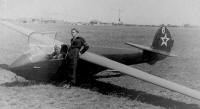
The PAI-6 was designed as a single-seater training glider to take advantage of thermal flight and had full aerobatic capabilities. It was generally similar to the previous PAI-5, but was notable for its increased wingspan.
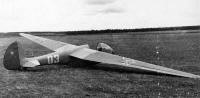
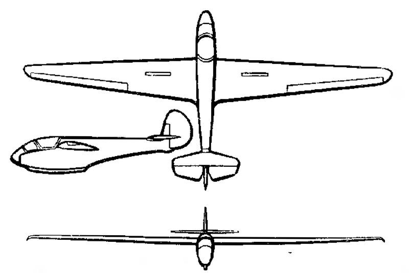
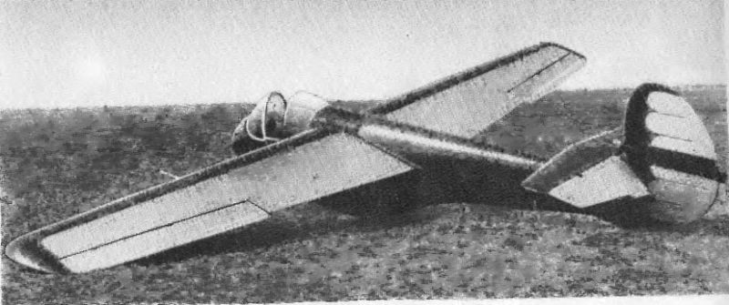
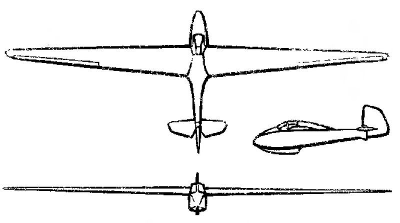
The PAI-6 was a high-cantilever glider with a large trapezoidal high-wing.
The glider was built entirely of wood. The fuselage had a simple construction made up of 24 frames joined by three stringers and a set of stringers. The exterior coating was made with plywood between 1.5 and 2 mm thick. The cross section was oval, with downward elongation. In the upper part of the fuselage, a slit was made, crossed by the force elements of the wing. An aluminium cover was placed over this slit.
The wing composition comprised two trapezoidal-shaped consoles in plane joined at their bases on the longitudinal axis of the apparatus. The consoles had a TsAGI R-Sh profile of constant relative thickness (15.5%) and were fixed to the fuselage by means of four points of two reinforced frames located in the upper part. The two consoles were joined together by screws and conical fixings. The fixing points to the frames were located on the spar and on the last wing spar.
The wing featured a single spar structure with ends working by twisting. The stringer was made up of two faces with plywood partitions. The wingtips and the frontal region of the wing were covered with plywood and the rest with fabric covered with paint.
The ailerons were attached to an auxiliary spar at three points and featured a single spar structure with diagonal ribs. The front part was covered with plywood and the rest with fabric. The wing-end interceptors were conceived as smooth pine frames with fabric covering on both sides. Each interceptor was attached to the wing spar by three points.
The horizontal tail plane was raised to the top line of the fuselage and positioned in front of the vertical tail. The stabilizer featured a single spar construction with plywood overlay. The elevators also used a single spar and coating similar to that of the ailerons.
The keel was an integral part of the fuselage construction and ended in a rudder with aerodynamic compensation. This rudder featured a two-stringer structure. From the leading edge to the second spar the covering was plywood and from there on fabric. All rudders featured three-point fixation. The landing was made on a wooden ski, with a trunk structure, located in the lower part of the fuselage.
The cockpit, located in front of the wing, was closed by a cover that protruded from the upper line of the aircraft. The flight control was mixed with control of the ailerons by means of ropes and bars for the control of the tail planes.
The control of the interceptors and the tow hook was also carried out by cables, with actuators located on the sides of the cockpit.
Once the tests were completed from the GK NII VVS Experimental Factory, improvements were made to the original design and the entire set of plans and technical diagrams was created to launch production. In Ryazan, Moscow, a small series was built in 1949. Its main destination was the flying clubs of the country. PAI-6 participated in several air parades for Aviation Day in Túshino.
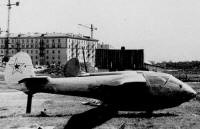
An improved version of this glider known as PAI-6M was built in the early 1950s at the MAI. This aircraft was never flown and was destroyed as a result of the cooling towards the gliders that occurred in the USSR in those years.
PAI-6 Wingspan: 12.4 m Wing area: 11.8 m² Aspect ratio: 13 Length: 5.41 m Height. 1.35 m Glider weight: 193 kg Wing loading: 24 kg / m² Stabilizer surface: 0.9 m² Elevator area: 0.75 m² Keel surface: 0.17 m² Rudder surface area: 0.85 m² Spoiler area: 1.58 m² Minimum descent speed: 0.82 m / s Cruising speed: 85 km / h Landing speed: 60 km / h Max glide ratio: 24 Accommodation: 1
Between 1947 and 1948, the test pilot and aeronautical constructor Alexei Ivanovich Pietsuj developed two new projects at the MAI that were called PAI-5 and PAI-6. The Pietsuj PAI-5 (Russian: Пьецух ПАИ-5) was designed as a single-seater competition glider and was built at the GK NII VVS experimental factory in 1947.
The PAI-5 was designed as a high cantilever glider with a small trapezoidal wing.
The glider was built entirely of wood. The fuselage had a simple construction made up of a series of frames joined by four stringers. The outer covering was made with plywood. The wings had an R-Sh profile. The wingtips were covered with plywood and the rest with paint coated fabric.
The horizontal tail plane was raised to the top line of the fuselage and positioned in front of the vertical empennage.
The landing was made on a wooden ski, with a trunk structure, located in the lower part of the fuselage.
The cockpit, located in front of the wing, was closed by a cover that protruded from the upper line of the aircraft.
The PAI-5 glider was tested in February 1948. Pietsuj himself flew the model in front of a group of renowned test pilots, most notably Air Marshal Ye. During the test flight the complete set of high school aerobatics was executed and an overload of 8g was achieved at speeds of 220 km / h.
During the celebration of Air Fleet Day in 1948 Pietsuj made a demonstration of high school piloting. For the design and construction of this glider AI Pietsuj received the Order of the Red Star.
The Pietsuj PAI-3 (Russian: Пьецух ПАИ-3) was a glider designed and built by Alexei Ivanovich Pietsuj as a single-seater training apparatus for the preparation of Class B sport pilots and was built in 1937.
It was designed with the aim of replacing the Gribovski G-9 and Antonov BS-5 gliders, already outdated for the time. It was necessary to have a training glider capable of being towed from another plane and performing all kinds of high school stunts in all weather conditions.
The PAI-3 was designed as a high-wing cantilever monoplane with a trapezoidal wing and high aspect ratio.
The fuselage had a simple construction made up of a series of frames joined by four stringers. The outer covering was made of 2 mm thick plywood covered with fabric.
The wing construction incorporated a single main spar, a secondary spar, and a set of ribs. To fix the ailerons another small auxiliary spar was used. The wing tip was covered with plywood, but the rest of the coating was made of fabric covered with several layers of paint.
The empennage featured a large rudder attached to the shallow keel at three points. The horizontal empennage featured two non-stabilized elevator rudders.
At the bottom of the fuselage there was a ski with a trunk structure, without amortization.
The spacious cabin featured an angular deck constructed of duralumin and celluloid.
From a production point of view the Pietsuj PA-3 glider was easier and cheaper to produce than the Gribovski G-9 and Antonov BS-5.
The flight tests of the PA-3 glider were developed by pilot PI Shelest. Despite showing good performance, series production was not approved. Only the one prototype was built.
Alexei Pietsuj was born in 1918 in Vínnitsa, Ukraine. At age 16, he built a small glider, called PAI-1, in which he learned to fly and demonstrated at Aviation Day parties in Kiev. For this device he would receive the award for the youngest constructor in the national competition for light aircraft.
Alexei Ivanovich Pietsuj (Russian: Алексей Иванович Пьецух) was born in 1918 in Vínnitsa, Ukraine. At age 16, he built a small glider, called PAI-1, in which he learned to fly and demonstrated at Aviation Day parties in Kiev. For this device he would receive the award for the youngest constructor in the national competition for light aircraft.
Later, working in the Osoaviajim Glider Factory and under the direction of Oleg Konstantínovich Antonov and BN Sheremetiev he would build his second model, called PAI-2 “Pavel Golovin” in 1937, followed by PAI-3in 1937 itself. Pietsuj worked as a teacher at the glider school, developing the PAI-4 tailless glider in that period.
From 1939 on he was called up to serve in the ranks of the Red Army.
During the Great Patriotic War he served as a tug pilot in the glider section of the air landing troops. He was tasked with piloting an Ilyushin Il-4 to tow gliders towards the front line, but Pietsuj requested a fight. After his request was denied three times, in reply he made a dead link between Nesterov and the Il-4. His performance was branded as “dangerous vandalism”, for which he was handed over to a court, demoted to the ranks and sent to a punishment battalion. On his first night he made seven combat sorties in a Polikarpov Po-2 bomber. After two months the accusation was withdrawn in court.
As a pilot of the 44th Guards Bombardment Aviation Regiment and the Don Red Flag belonging to the 9th Guards Bombardment Division, he carried out 91 combat sorties. He participated in the fighting for Warsaw.
In the spring of 1945 in Germany and with the help of several soldiers, he managed to assemble a flight-capable Messerschmitt Me-410 using components from three aircraft. At the controls of the Me-410 he airlifted it to Moscow. In June this aircraft was tested on the NII VVS.
After the victory he began working as a test pilot in the GK NII VVS, serving in the V. Ye squad. Golofastov. At this stage he built the PAI-5 (1947) and PAI-6 (1949) gliders with aerobatic capacity, which participated in several aerial demonstrations for the Air Fleet Day in Túshino. He was the test pilot PAI-5 (02- 1948) towed gliders Antonov A-7 from Ilyushin Il-4. As a test pilot he flew in more than 60 types of aircraft and gliders.
In the early 1950s Pietsuj organized a student construction bureau among the students of the Moscow Aviation Institute. In this institution he developed the glider models PAI-6M (1952), MAI-56 (1956), MAI-63 (1964), MAI-68 “Pushinka” (1970) and the MAI-58 (1958) and MAI- 62 (1962), as well as the MAI-63M motor glider. He personally tested the MAI-53 models in 1954, MAI-56 in 1958, MAI-62 in 1965, MAI-63 in 1964 and MAI-63M in 1965.
He lived in the village “Liotchik Ispitatiel” (Test Pilot) of the city Iksha, in the Moscow suburbs. He built a house made of bottles there. He died in 1994.
Military grade Captain
Awards and distinctions Order of the Great Patriotic War Second Class (5-02- 1988) Twice Order of the Red Banner (04- 1945, 1948) Medals
Pietsuj was the author of several articles published in the pre-war period in the magazine “Samoliot”.
He wrote the book “Krylya Molodiozhi” (Youth Wings), published by the Moscow publishing house “Oborongiz” in 1954.
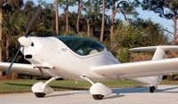
Phoenix Air’s honcho Jim Lee counts 14 more aircraft on his backordered list—a major LSA success story. The 49-foot span, Rotax 912ULS-powered low-wing taildragger won Sun ‘n Fun’s Best Commercial LSA award in 2012 and received three more sales. Base price 2012: $149,000. Phoenix Air was rolling out a new Phoenix S-LSA motorglider every 18 days. They registered 10 aircraft in the US in 2012.
Under development in 2012 was the all-electric ePhoenix, using an in-house built motor and electronic flight controller. So far, flights have yielded one-hour durations, this is a two-seat LSA.
The Elfe series started from a 9 m sailplane designed by W.Pfenninger before World War II. A new design was introduced by him in 1947 to become the Elfe 2, probably the first sailplane with a laminar flow airfoil. Subsequently the series was further developed by Markwalder to become the Elfe PM-3 (brought to the US in the sixties), then by Albert Neukom the Elfe M, Elfe MN and AN66 before the Standard Elfe S-1
A 1922 single-seat tandem-wing glider, 6.6m span (main), 2 built aka Peyret Tandem (orig. name), Alérion Tandem, or simply the Planeur Peyret
Alérion n° 1: Maneyrol set duration record (3h22), Itford Hill, 21 Oct 1922 Alérion n° 2: written-off by Lt. Le Petit near Biskra, Algeria, 12 Feb 1923
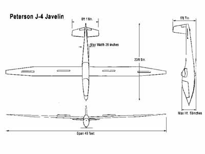
The Javelin dates back to the early 70’s in America when one person tried to produce a low-cost glider in an effort to stem the rising importation of the popular German gliders.
Early sketches were for the best performing aircraft in the world, but it was only a couple of weeks until that philosophy had changed. What was really needed was a Certified Sailplane that the public could rent and afford to buy. What was needed was a sailplane that was not perfect, just good. The new priorities were: low cost. 30: 1 glide and easy maintenance. The project became known as “Easy-Do” at that stage. Six years, later it seemed a good idea to drop that title and just call it the J-4 Javelin.
The ship was literally designed from the inside out. Cost was paramount, so design of the wing structure was the first step. A spar without rivets, pieces, or bolts was what was needed, and a tube spar was chosen as the best solution It uses a six-inch tube and tapered its wall thickness by chem-milling. The wall of the tube tapers in thickness from .188 in. at the root to .050 in the first ten feet and remains constant after that. Full tube diameter rings under each rib were left, so that rib cut-outs would be the same. Also an uncut strip spanwise on top and bottom made the tube tangent to each skin surface. Studies showed that twelve spars could be chem-milled at once for a cost of $8.00 each for the tank time. Masking the tube for cutting was only $18.00 each-an obvious saving compared to driving 1500 to 2000 rivets and root fittings.
With the basic method of fabrication chosen, the wing size was selected: a six-inch diameter tube with an 18% airfoil gave a 33.33-inch chord, and a forty-nine foot span equalled an area and aspect ratio that were acceptable. Wing skins were sized to take advantage of full or half sheets to minimise wastage and keep cost down. The trailing edge is glued on (no rivets) and the rear spar and aft ten inches of the wing are bent from one piece of metal. (Thet saved a few rivets) A straight wing was designed first. It seemed the obvious way to keep cost down. Flight tests with the straight wing showed what any aerodynamicist knows — it has a higher drag than a pure elliptical planform. Since an ellipse is expensive and impractical, and a straight taper from root to tip is just about as bad cost wise, the Javelin wing tapered starting two-thirds of the way out front the root. Incidentally, this approaches the elliptical plan form better than the complete taper.
Before building the first set of wings, another important decision was made. Most aerodynamic studies of surfaces moving through air at 60-70 mph seemed to indicate that exposed rivets didn’t damage performance very much, and flush riveting is expensive. Also, since blind rivets were easier to install than solid two-man bucked rivets, the design would be tailored for blind rivets. The FAA-approved structural blind rivets are the Huck and Cherrylock rivet types. These sold for fifteen cents each, even in the large quantities. That would have been $1500 just for the rivets if it had the usual 10,000 per airplane!
A blind rivet produced by a local firm had one length that would serve all needs. The head was custom moulded when installed to a low .030-high domed rivet, and best of all it swelled sideways to fill out-of round or oversized holes. It also sealed itself so it was pressure tight. Cost per aircraft would be $60.
The FAA sent its “Dear John”- a letter saying they had never heard of the rivet, and that it wasn’t on the approved list. The FAA were asked, “If it holds the static test loads, we’re going to use it.”— They said, “How about vibration?’ Question – “In a sailplane?” They said, “Our rules (which don’t cover sailplanes) say eight million cycles while under shear loads.”
After $1000 worth of vibration testing by one of those special labs that shake, bend and twist things, the FAA sent a nice letter approving the rivet.
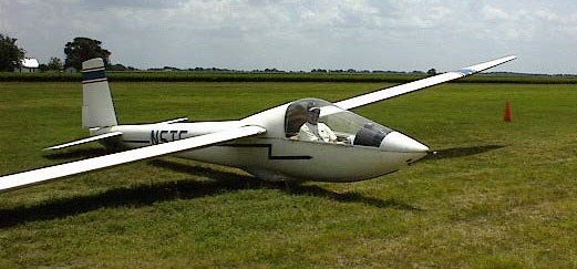
Cost studies suggested that an aileron didn’t earn its keep, and if a wing could he built without one it would be a lot less expensive. That’s when it was decided to use spoilers for roll control.
They were less expensive and the yawing drag was in the right direction (which isn’t true with the aileron). As a test a linkage to the right spoiler in a single-place was disconnected, leaving only the left spoiler operative. It soared quite well; making left turns with the spoiler handle. The first Javelin wing had spoilers laying flat upon the top skin surface; later recessed them into the wing to improve performance.
The tail assembly has all three surfaces identical (i.e. one aerodynamic surface can serve interchangeably as a rudder or either elevator). The main spar is a two and one-half inch steel tube cold-swaged in a straight taper down to a one and one-half inch diameter.
It is simple with no built-up parts, provides an ideal pivot for a full-flying surface, is easy to attach and again the cost to swage the heart of the structure was only $9.00. Since flying slab surface was aerodynamically balanced, a small anti-servo tab was added to give control feel. The leading edge has a full length weight inside to partially static balance the surface. Originally piece of concrete reinforcement rod bonded in place with a rubber mould compound was used. They couldn’t prove to FAA that it wouldn’t fall out, so instead of arguing, the weight was changed to a thick-wall tube riveted in place. (Incidentally, those old leading edge tail surfaces still have the bonded concrete reinforcement rods in them and they can’t get them out)
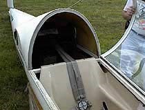
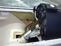
The fuselage is three major basic assemblies. A square steel frame (easy to cut and fit joints) goes from nose to tail and offers good pilot protection plus holding the wheel and all the controls right out in the open where assembly is easy. Fibreglass lower shell 24-ft. long acts as a structure and fairing for the fuselage. The third piece, an aluminium sheet metal deck behind the wing and extending to the tail, completes the basic fuselage. All three pieces are riveted together with one row of rivets through the aluminium sheet, fibreglass hull, and steel frame.
The wing-mount is a piece of tubing that has been bent 4 degrees (2 degree dihedral) and attaches to routed plates–the inside has been chem-milled to increase the diameter so that the wing spar will slide into it. Since the tube will take bending and shear loads in all direction, the rear spar serves only as a reaction for wing torque; hence simpler structure and lower cost. I looked for three weeks to find out how to bend a six and one-half inch diameter, 1/4 in.wall tube four degrees. An old gentleman who owns an oil well equipment manufacturing company in Tulsa, Oklahoma, and he gave a note to his foreman and told Peterson to send the parts back there. Both airfreighted and within a week 5 bent tubes were done. He never did send a bill.
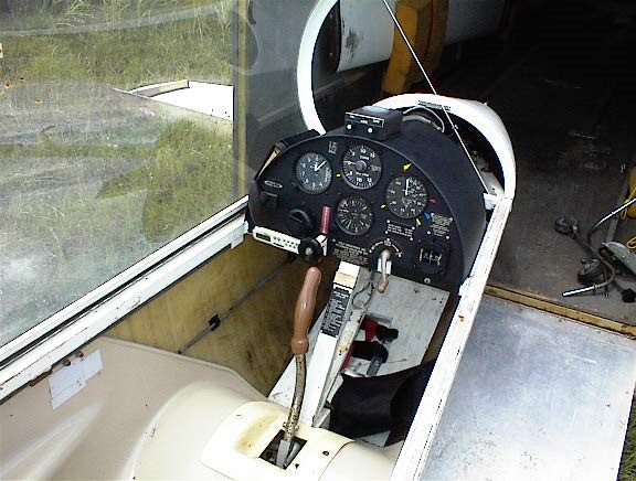
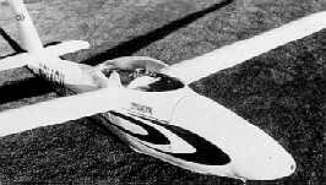
The canopy is 26 inches wide five feet long, free blown and optically perfect. Eye level is at the top of the wing so that you can watch the action of the spoilers and spoilerons and have almost unlimited visibility. The canopy is en-trapped within a special extrusion and is not drilled for bolts.
On Nov. 4, 1969, Peterson flew the ship for the first time on El Mirage dry lake using auto-tow. Five times up and five times down. The spoilerons did work.
At this point a couple of USAF test pilots and they took over the test flying. The first air-tow was at Tehachapi and Major Mike Love was at the controls. On auto-tow, at 60 mph, the spoilers stayed closed: at 65 mph on air-tow they came open different amounts This caused yaw and roll problems. At release (5000 ft. AGL), Mike put the nose down and at 70 mph the ship flew straight again because all spoilers were open the same amount. It had achieved an L/D of about 4 to 1. Mike added 20 mph and flew his downwind and base at 90 mph with touchdown at 80. The end result of research was to recess the spoilers. With spoilers cut into the wing surfaces and a new tapered wing built, things started to brighten up. They had made parts for five or six ships, so a new wing or fuselage really wasn’t too big of a problem.
We our flight test work moved from Tehachapi to Rosamond Airport for convenience, since it was closer to home and pilots, Major Love and Major Staten. An exact ground distance between 2 points of 3 miles + 85.6 ft. checked airspeed indicator accurately.
Flight test work for FAA information was expensive and time-consuming. Between pilot schedules, weather, and schedule, the weeks did drag on. Most spectacular were the spins. Three turns were required in each direction with controls in every position possible.
The FAA pilot, Norm Moentmann, had landed and Peterson pulled the Javelin to the sidelines and started to tie it down. A NASA DC-3, sitting on the line, started its engines and the open canopy caught the blast. With short hinge pins in it for the flight test work the air loads knocked it off the ship. A few small scratches and a broken hinge on the fuselage side were the only damage. A quick trip back to the shop in Newhall, picked up some parts, and spent part of the night fixing it so that testing could continue the next day
In January 1973 the FAA couldn’t have issued the Javelin an ATC if they had wanted to because the environmental laws on noise abatement arbitrarily included gliders! The law seems to have been written without specific values-just anything new coming out had to be made quieter. Finally reason prevailed somewhere, and they got a letter saying it wouldn’t apply to the J-4.
On Thursday, February lst, 1973 FAA pilot, Norm Moentmann landed the ship. “I’ve flown it enough,” he said, “it’s okay.”
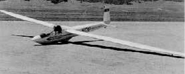
So the J-4 is an ATC’d sailplane that goes together in ten minutes with all the controls automatically hooked up, is low in cost to produce, looks reasonable even with exposed rivets, has a 30-to-1 glide, and flies well. It has been flying up to 150 mph and have done a complete flutter test program up to 140mph.
Designed and built be Harry Perl, the Penetrator first flew in 1953. Built from wood and fabric, it has an all-moving tail, styrofoam-filled wing leading edges, and airbrakes. It originally had a skid with jettisonable take-off dolly, but was subsequently fitted with a fixed wheel. The sole example now belongs to the National Soaring Museum.
Wing span: 14.63 m / 48 ft Wing area: 12.07 sq.m / 130 sq.ft Empty Weight: 218 kg / 480 lb Payload: 90 kg / 200 lb Gross Weight: 308 kg / 680 lb Wing Load: 25.51 kg/sq.m / 5.23 lb/sq.ft L/DMax: 33 84 kph / 45 kt / 52 mph MinSink: 0.64 m/s / 2.1 fps / 1.24 kt Seats: 1 Aspect ratio: 17.75 Airfoil: Go 549