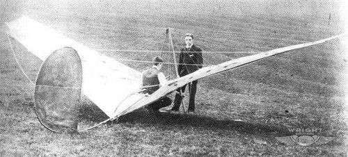
Paul Poncelet started at SABCA as a foreman. Passionate about gliding which was starting across the Rhine, it was not long before he designed a glider, which he built with primitive means after his daily work, and devoted his evenings to it for eight months. On February 10, 1923, his glider – the first airplane without an engine to fly in Belgium -, called “Castar”, was brought to Haren at SABCA, where the pilot Victor Simonet made the take-off, launched pulled taut by helpers.
Glider
Polikarpov BDP
The 23 of January of 1940 the Commissariat of Aviation Industry created the Directorate for creating landing gliders. In the autumn of that year, in an extraordinary meeting, with the presence of Stalin, the decision was made to launch a competition for the development of airplanes of this type and their series production. The best would be mass-produced and used successfully in operations during the Great Patriotic War.
Nikolai Polikarpov had no experience in glider design, so he did not participate in the competition. Despite this, at the beginning of June 1941 its construction bureau, unexpectedly for many, presented a project for a landing glider. The production of gliders was carried out not in aviation factories, but in carpentry and furniture factories.
The Polikarpov glider was designed as an aircraft to support penetration units. After analyzing the losses of the Germans during the landing operations, the Soviet aircraft manufacturer came to the conclusion that it was possible to reduce them by using well-protected and armed means of landing. To achieve this objective, he designed a glider from which the landing troops, before launching themselves, could direct fire against enemy positions, using their light weapons. The protection of the device was obtained through the use of removable armoured plates, which once landed the glider allowed to create a defensive barrier for the soldiers.
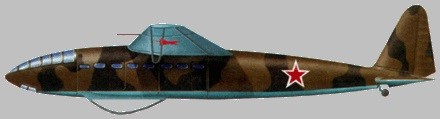
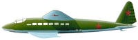
The new glider was named BDP (Russian: Поликарпов БДП), after Boyevoi Disantni Planior or Military Landing Glider.
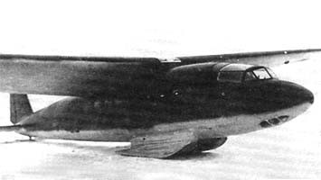
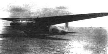
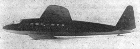
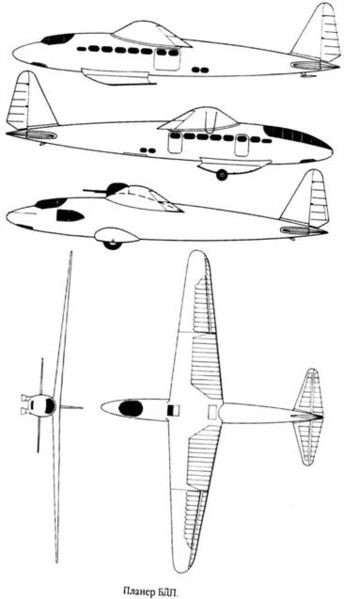
The BDP landing glider was desiigned as a high-wing monoplane with a 20-meter wingspan and an aerodynamically designed fuselage. The entire construction was made of wood.
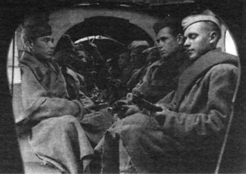
Designers put special emphasis on making an airplane cheap and easy to produce. Due to its dimensions, the BDP was capable of transporting 16 soldiers with their equipment and its towing had to be carried out by Túpolev SB or Ilyushin DB-3 bombers. The fuselage was entirely made of wood. The pilot had an emergency cover with a structure also in wood. To improve visibility during landing, the lower part of the cab was glazed.
The landing troops sat on benches located on the sides of the fuselage, forming part of the structure. Between the two rows of benches there was a 600mm corridor. The exit of personnel and cargo was carried out through two 900 x 950 mm doors, one located in the front region on the right and the other in the rear on the left. In the first BDP copy there were two small doors on the right and two on the left.
In the lower part of the fuselage, behind the cargo area, a hatch was prepared to parachute from the glider.
The wing of the BDP was made of wood and had a single spar. The coating of the leading edge and the force points was done with plywood. The rest of the wing was covered with fabric. The wing profile used was the NACA 230. In order to reduce the landing speed in the section between the ailerons and the fuselage, Shrenk-type flaps were installed.
In the area of the leading and trailing edges of the wing, special hatches were located to allow firing with light weapons, covering the upper hemisphere. To defend the tail a section of the upper rear fuselage could be raised and become a firing point for the gunner.
The tail was monoplane and cantilever, constructed of wood covered with plywood and fabric.
The landing gear consisted of two ash skis placed on leaf springs to absorb the impact. The junction of the skis and the fuselage was covered by fabric covered fairings. For landing the BDP used a 400 x 150 mm four-wheel detachable wheelbarrow.
The glider did not have its own weapons, but did have attachment points for seven DP-type infantry machine guns. Two machine guns could be installed to defend the upper hemisphere, one in the lower hatch and two on the sides.
Inside the fuselage were 12 5.5 mm armored plates with dimensions of 480 x 550 mm. The pilot had armor on the back of the seat. All this protection added 127 kg to the weight of the glider.
The development of the BDP project was carried out by Polikarpov and his collective during the month of June 1941.
The project was approved by the NKAP management and it was decided to carry out the construction of the prototype at Factory No.51.
By the end of the summer of 1941 the glider was finished and ready for flight tests. The first flights were carried out in September and took place from the LII airfield in the Moscow suburbs. As a tug, an SB bomber with M-103 engines was used. The glider was piloted by VP Fyodorov.
Only 14 flights were made, which were interrupted on October 14 due to the advance of the Germans and the beginning of the evacuation.
As a result of the tests, defined as inconclusive, it was concluded that the BDP was stable in flight and that it could be maintained with free controls. The effectiveness of the rudders was acceptable, both during flight and on landing. The piloting technique was simple and did not demand a great qualification from its pilot, which ensured its control by pilots who had flown training gliders.
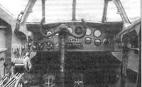
The negative aspects were the lack of structural strength at various points on the wing and fuselage. This caused that during the tests the flight weight was limited to only 2200 kg and the speed up to 220 km / h (the glider having been calculated for 3200 kg and 320 km / h respectively). The pilot pointed out that the curved glass in the windshield distorted the vision and proposed to replace it with a normal one made of straight pieces. When the aerodynamic brakes were extended, there was creaking in the tail area.
It was recommended to work on solving these problems and then present the model for series production. In relation to this process, there were no difficulties, since the construction could be carried out in carpentry with basic equipment. TsAGI specialists warned that the production cost of the Polikarpov model exceeded that of other similar gliders.
This first specimen was evacuated by air in October 1941 to the west. Curiously, during the flight of this unknown aircraft towed by an SB bomber, a group of fighters from Moscow’s anti-aircraft forces (PVO) went out to intercept, forcing the glider to land near Kashira. The glider was looted by the local inhabitants and in that condition it was returned to Moscow shortly thereafter.
The second specimen, called BDP-2, was built in Novosibirsk, where Factory No. 51 in Moscow and the KB in Polikarpov were evacuated.
The glider was delivered for testing to the LII affiliate on February 6, 1942 and flown by II Shelest.
The BDP-2 presented a reinforced construction in relation to the original model, which brought with it a certain increase in weight. Externally it was also something different. The pilot’s windshield featured flat glass pieces and various elements were simplified. The trailing edge of the height and steering rudders was made by means of a steel cable as was the style in the first Soviet aircraft.
The tests of the BDP-2 with ski landing gear lasted until March 14, 1942. During this time several attempts were made to lessen the problem of tail creaking. The results improved after drilling a series of holes in the aerodynamic brakes, thus reducing the turbulence of the airflow.
The test conclusions again emphasized the simplicity of the piloting, the high payload capacity, good manoeuvrability and stability in different centering regimes. Serial production of the model was recommended.
Almost in parallel with the flight tests, the search began for a possible production base to develop series production. After reviewing various factories and companies in the region near Novosibirsk, it was decided to select the Siberian Military Region Workshops. These facilities had previously functioned as auxiliary production capacity for Factory No.153, dedicated to the manufacture of skis.
The first figures showed a number of 100 gliders with a unit cost of 41,125 rubles.
While negotiations were taking place, a new production site was defined. It was the Stalingrad Factory No. 490. In the middle of the summer of 1942 the plans and all the technical documentation were transferred there from Novosibirsk. Soon the military situation changed and the arrival of the Germans in Stalingrad thwarted production plans.
Along with the inability to produce in Stalingrad the opinion of the VVS was a lack of need to produce the BDP. The course of the war had shown little chance of success and there were already produced successful models A-7 of Antonov and G-11 of Gribovski.
In July 1942 the BDP-2 was destined to serve as a transport in the direction of the Moscow – Irkutsk air force. Several flights were carried out towed by a PS-40 (postal Ant-40) on the Novosibirsk – Omsk – Sverdlovsk route and vice versa. This route was also covered by several Antonov A-7s . The results of these experimental flights were impressive and it was proposed to build several examples of transport gliders for civil use with Aeroflot.
In 1943, at Factory No.51, the assembly of 10 copies of the BDP began. It is known that until the end of the year only two copies had been delivered. A third and fourth specimens were 98% complete, the fifth at 80%, the sixth at 28%, and the seventh only at 10%. No evidence has been found after that date.
Polikarpov, in an attempt to achieve full autonomy for the BDP, decided to develop a motorized model that was named MP. A prototype was successfully built and flown, but it was not mass-produced either.
Polikarpov BDP
Wingspan: 20.00 m
Length: 13.60 m
Wing area: 44.72 m²
Empty weight: 1470 kg
Normal weight: 3408 kg
Crew: 1
Payload Capacity: 16 Soldiers Equipped
Platz Glider
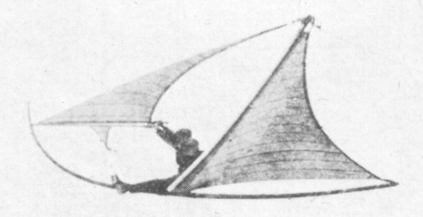
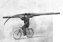
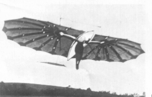
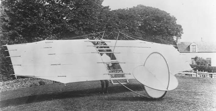
In Germany, just after the end of World War I, the 1919 Versailles treaty imposed a ban on powered flight. As a result there was a rapid increase of interest in gliding. Rheinhart Platz, the chief designer for Fokker’s after June 1916, perceived a role for a glider that was cheap to buy, costing less than “one good pedal cycle”, and cheap to maintain, while being robust and capable of being transported, by train or otherwise, and rapidly erected by one man.
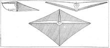
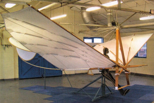
In the winter of 1922/23 Reinhold Platz designed and constructed a glider. The idea occurred during a sailing trip on the Schelde. To a certain extent sailing on water can be compared (aerodynamically) with gliding. After several tests with small and large models, Platz constructed a full size glider. Its fuselage comprised a curved steel tube with a circular section wooden beam inserted through it at the rear. The wing spars were two wooden masts which were inserted into two receptacles welded to the fuselage tube near the pilot’s seat. The “main sail”, or wing, was attached to these two masts. The two separate forward jibs were attached to jib masts, which could be moved by the pilot simultaneously or separately as required. By moving the two jibs up or down, longitudinal control was obtained. By moving one jib up and the other down, lateral control was possible. They were initially hinged together at their leading edges, but later the hinge point was moved rearwards towards the aerodynamic centre to reduce pilot load and separated only behind the hinge.
Since there were no ribs, the airfoil was determined by the airflow and the pilot, as for the sloop’s jib. The main wing, a single surface stretched between the spars and the extreme tail, also had its camber determined by the airflow, like the mainsail of the sloop. Both wing sheets were produced by sewing together narrow strips of material; the longitudinal joints between them are prominent in some back lit, better quality images.
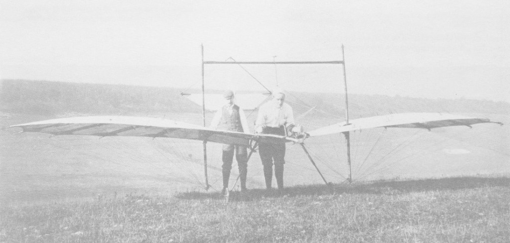
The glider had a wing span of 6.60 metres and weighed 40kg. It could be assembled by one man within 15min, and dismantled within 10min. The Platz could be disassembled into a 3,300 mm (130 in) × 350 mm (14 in) × 250 mm (10 in) pack, weighing 40 kg (88 lb) in fifteen minutes and reassembled in ten. Transport by bicycle, with care, was possible.
Free flight trials began some 50 flights without pilots and with increasing loads (up to 75 kg (165 lb)) into strengthening wind and eventually over sandhills as high as 25 m (82 ft). With a pilot in place, the glider was then flown tethered like a kite, first flying in February 1923. Several people, with weights up to 100 kg (220 lb) flew it this way, all reporting that forewing control loads were low. In February 1923 it was free flown in a moderate wind over 10 m (33 ft) dunes. Platz decided that the dunes did not provide usable soaring, their next goal, after which the experiments would end. He noted that, whilst his design could not compete with the best conventional gliders, it had met the initial targets outlined above and thought it or something similar would be of great value, seemingly content to leave others to judge his design.
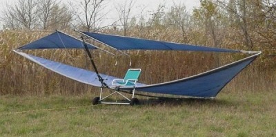
Modern copies have since been built.
Wingspan: 6.60 m (21 ft 8 in)
Wing area: 16.0 m2 (172 sq ft)
Empty weight: 40 kg (88 lb)
Crew: One
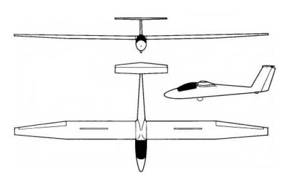
Pipistrel Apis-Bee
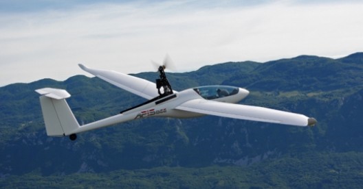
Apis/Bee is a single-seat middle wing ultralight self launching glider with a T- tail. All plastic parts are made in AFK, GFK and CFK technology while all main parts are LN certified. The plane itself is made of armoured plastic in combination of epoxy resin enforced with honeycomb, glass, carbon and kevlar fibers, featuring the same wing and tail section aerodynamics as the Sinus and Taurus. The wings are made in sandwich construction. Top and lower surfaces are made first then all additional elements (main spare, basic ribs, air-brake enclosure) are glued into top half. Air-brakes expand from the top half of the wing only. The rudder is built the same way from two halves with built-in control connections and hinges.
The fuselage is built in combined AFK and CFK manner as a combination of shell and sandwich construction. The two halves are are built so that most of the elements are glued into one of them and then both are put together. Carbon and kevlar are used from nose to wing section, while the rest is made in sandwich construction. The cockpit is covered with a single piece Plexyglass cover opening forward. Pitot tube and air vent (for ventilating the cockpit) are built into the nose. Static pressure is measured on the side of the fuselage. A radio antenna is built in to the aft vertical stabilizer. The tow tie is mounted on the lower front part of the fuselage. Rudder pedals are adjustable.
Horizontal stabilizer and rudder are made the same way as wings: in sandwich construction. All controls hook up automaticaly. Air-brakes and ailerons use rigid connections (tubes and bearings). Landing gear is a non-retractable wheel with disk brake under the cockpit and a small one on the tail. The wheel brake is accessible by air-brake handle.
The basic price includes the 14.97 m wing-span tail-wheel single seater ul class glider with integrated winglets, t – tail ready to fly, test flown. Standerd are a 4 point seat belts, a defogging system for the canopy, 6 stage positive and negative deflecting flaperons, self locking Schempp-Hirth type airbrakes, spring-type elevator trim, in flight adjustable rudder pedals, 4˝ main wheel with disc brake and fairing, two wingtip wheels, 2 ½ ˝x 1 ˝, with fairings, steerable tail wheel 180 x 45 mm (7˝x 1 ¾˝), 14 – liter fuel tank, Hirth F33bs or Rotax 447 belt drive engine, high capacity dry-type battery 12 v / 10ah, modular electric system with fuses on primary and secondary circuit, electric starter, regulator-rectifier, fully automatic engine control and propeller positioning system, 2 blade wooden propeller reinforced with fiberglass, and an instrument panel with:
master switch key, switches with fuses and warning lights, magnetos switches,
instruments: multifunction instrument to control the engine operatiom and the system
to retract the engine, engine hours counter, rpm counter, cht, egt, altimeter,
airspeed indicator, variometer, libelle (slip indicator) & magnetic compass with mount.
Apis/Bee
Wing span: 14.97 m
Wing area: 12.24 sq.m
Aspect ratio: 18.33
Fuselage length: 6.26 m
Overall height: 1.3 m
Empty weight: 215 kg
Single wing weight: 40 kg
Max. takeoff weight: 322.5 kg
Min. takeoff weight: 250 kg
Max. speed Vne: 220 km/h
Max. airspeed in rough air: 144 km/h
Max. airspeed in aero-tow: 144 km/h
Manouvering airspeed: 144 km/h
Max. speed with air-brakes: 220 km/h
Min. speed MTOW: 60 km//h
Airfoil type and ratio: IMD 029 17.01 %
Best glide ratio @ 94 km/h: 39-1
Min. sinking rate @ 84 km/h: 0.59 m/s
G load limits: +5.3 -2.65
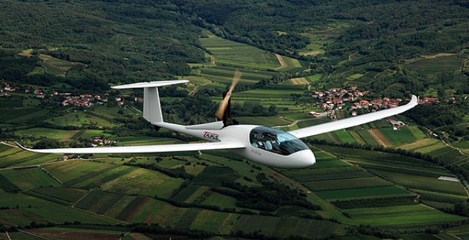
After the success of the Sinus it was quite realistic to expect there is also a market niche for a real microlight two-seat glider, as well as it’s version with an auxiliary, fully retractable engine. Hard-core glider pilots were not convinced by the glide ratio of 1:30 that Sinus has to offer. The ‘real’ quality gliding goes together with glide ratios of 1:40 and more.
This time, the main idea of construction was different from the Sinus, but the aims were a side-by-side microlight motorglider, with a self-lauchable version with an auxiliary, yet fully retractable engine and glide ratio of at least 1:40.
by providing two main wheels in parallel configuration complete independence could be achieved dispensing with a helper holding the wing tip during take-off.
The fuselage of Taurus uses a lifting body shape concept and features enough room for an auxiliary, yet fully retractable engine.
Taurus is also intended for training, therefore all controls must be within reach of both pilots. Both pilots have individual control sticks and rudder pedals. The landing gear operation lever, flaps, airbrakes, tow rope release and trim levers are there for common for both pilots and are found in the middle, between both seats. For added comfort pilots enjoy adjustable headrests, in-flight adjustable rudder pedals, separate vent window and a central ventilation system for efficient de-fogging of glass surfaces. There are side pockets for each pilot and a baggage compartment behind the seats with space for an oxygen system as well.
The version of Taurus with an auxiliary retractable engine comes with a ROTAX 503 which is modified and redesigned by Pipistrel. The engine is twin carbureted engine and drives Pipistrel’s own developed propeller. The system for extending and retracting the engine and propeller is fully automated. The pilot takes advantage of a dedicated interface on the instrument column and all they have to do is to flick the switch to ‘engine IN’ or ‘engine OUT’ position – everything else is done completely automatically. When retracting, the propeller is first positioned vertically, the engine then gets retracted and the engine bay covers close. To restart the engine on ground or in-flight the pilot selects the ‘engine OUT’ option and the engine extends and is ready for start-up in only 12 seconds. The entire engine retraction system is incredibly light and reliable, all switches and sensor used to monitor the operations are electromagnetic-induction type and as such not sensitive to vibration, mechanical damage and/or dirt. This system has also been developed in-house by the Pipistrel team. Built-in safety will prevent inadvertent start-up or retractions of the engine.
The same goes for the undercarriage retracting system, which is fully mechanic but needs very light force on the cockpit lever during operation. There are two main wheels in parallel configuration. The tail wheel is not retractable but fully stearable. The airbrakes, flaps and the elevator trim are all mechanical pushrod type. A tow-rope release mechanism can be fitted as well. Gliding has a 1:41 glide ratio coupled with 5 flaperon settings.
The LSA Taurus has a 15-meter wing-span which can be removed. Taurus has automatic control connections and one wing weighs 40 kg (90 lbs). From take-off to 500 m (1650 ft) needs only 3 minutes, 6 minutes to 1000 m (3300 ft) and 10 minutes to 1500 m (5000 ft).
Taurus entire cabin area is encased with energy absorbing structures made from Kevlar fibre. The Taurus can also be equipped with the ballistic parachute rescue system. Taurus is made in highest technology composites (epoxy resin, glass fibre, carbon fibre, kevlar fibre and honeycomb structures). The airfoil used on wings is ORL 170, (F. Orlando).
2009 Price: 70000 EURO
First announced in December 2007, the Taurus Electro matches the performance of the petrol powered Taurus 503 and, it weighs the same and sells for the exact same price. Taurus Electro has a tailor-developed 30 kW electric motor.
The electric-motor propulsion has been tested successfully on four light aircraft before the Taurus Electro – as an auxiliary engine on self launching gliders Apis, Antares and Silent and on the MCR light aircraft where a full-cell based propulsion was used.
Pipistrel’s Taurus is a two-seat glider with higher approved take-off weight than the single seat gliders where the electric-motor propulsion has been tested so far. Therefore the Taurus requires a more powerful electric motor.
The goals when designing the Taurus Electro were mainly to:
- develop a system, that will enable the aircraft to climb to altitudes in excess of 2000 meters on a single battery charge;
- keep the current market price of the aircraft;
- keep the current take-off distance;
- keep the empty weight of the aircraft within the values of the internal combustion engine powered Taurus 503 with fuel;
- keep the current climb profile of the aircraft.
This required modify the existing system for extension / retraction of the engine, developing a purpose-built propeller to maximize the efficiency at given constant torque, useing high-performance Lithium-polymer batteries with specific capacity touching 200Wh/Kg, and developing a system to charge the batteries in flight.
Developmental costs of the Taurus Electro project were over 1 Million Euro, partially funded by the EU for the sum of 354,824.89 EUR.
TAURUS 503
Engine: Rotax 503 UL DCDI 2V, 53 hp at 6600 rpm
Propeller: 2 blade Pipistrel 1600 mm diam
Wing span: 14.97 m
Length: 7.27 m
Height: 1.41 m
Wing area: 12.33 sq.m
Rudder area: 0.9 sq.m
Horizontal tail area: 1.36 sq.m
Aspect ratio: 18.6
Positive flaps: 5 deg, 9 deg, 18 deg
Negative flaps: -5 deg
Center of gravity: 23% – 41%
Empty weight: 285 kg
Minimum pilot weight: 60 kg
Maximum total pilots weight: 220 kg
Max take off weight (MTOW): 450 kg / 472.5 kg
Fuel tank capacity in the wing: 30 lt
Useful fuel: 27 lt
Stall with flaps: 63 km/h
Stall without flaps: 71 km/h
Manoeuvring speed: 163 km/h
Max. Speed with flaps extended: 130 km/h
Max. Speed with airbrakes extended: 225 km/h (extend at or below 160 km/h)
Max. Speed with powerplant extended: 160 km/h
Vne: 121 kt / 140 mph / 225 km/h
Min.sink: 0.70 m/sec
Min.sink speed: 94 km/h
Max. Sink with airbrakes: 6.0 m/sec @ 100 km/h
Best glide: 1: 41
Best glide ratio speed: 107 km/h
Best glide at 150 km/h: 1: 33
Best glide at 180 km/h: 1: 23
Max towing speed: 150 km/h
45°-45° roll time: 3.9 sec
Take off run MTOW: 180 m
Take off over 15 m MTOW: 265 m
Cruising speed with 75% power: 120 km/h
Best climb speed: 100 km/h
Max climb rate (MOW): 2.9 m/sec
Service ceiling MTOW: 3,900 m
Max load factor permitted (x1,8): +5.3g -2.65g
Max load factor tested: + 7.2g – 7.2g
Fuel consum. At full power:: 18 lph
Seat: 2
Cockpit width: 50 in
Taurus Electro
Empty weight (incl. Batteries): 320 kg
Top-of-climb: 2000 m / 6500 ft AGL
Take-off distance at MTOW (472.5 kg): 170 m / 560 ft
Climb rate at MTOW (472.5 kg): 2.8 m/sec / 560 fpm
Electric motor type: permament magnet synchronus three-phaes brushless
Electric motor dimensions (excl. propeller flange): diam. 250 mm x 150 mm
Electric motor mass (excl. propeller flange): 14 kg
Max. continous shaft power: 30 kW at 1800 RPM
Efficienty at max. continous power: 95%
Max. continous torque: 160 Nm
Peak torque: 200 Nm (0 – 1500 RPM)
Max. motor RPM: 1800 RPM
Nominal voltage: 140 V
Propeller diameter: 2040 mm
Batteries: Lithium-polymere: 42 cells, 3.7 V each
Storage capacity: 6 kWh
Battery weight: 46 kg
Charger / battery voltage balancer: Built into aircraft
Power / RPM controller: SAC 40 modified for aviation use
Pipistrel d.o.o Ajdovscina
In 1995 the owner of Pipistrel was Ivo Boscarol.
2009: GORIŠKA CESTA 50a, SI-5270 AJDOVŠČINA, SLOVENIA
LSA, power pack, trike and glider builder
Pilcher Hawk
Pilcher added bicycle wheels and a tow launch to his ‘Hawk’ for swifter starts, and more than 100 separate pieces of piano wire to hold the wings in shape. Many successful flights were made.
Percy Pilcher crashed and was killed in the Hawk on 2 October 1899.
First flight: 1896
Wing span: 7.1m / 23ft 4in
Length: 5.6m / 18ft 6 in
Weight: 23 kg / 50 lb
Pilcher Bat
In 1893 Pilcher had been appointed assistant lecturer in Naval Architecture and Marine Engineering at Glasgow University, and it was there, inspired by Otto Lilienthal, that he designed his first glider, the Bat, in 1895 and tested it at Cardross. In 1896 he made his first glides, under Lilienthal’s tuition. This was the second form of Bat, with a bisecting circular fin and tailplane. Longer flights were made, some under tow when the wings’ dihedral was reduced.
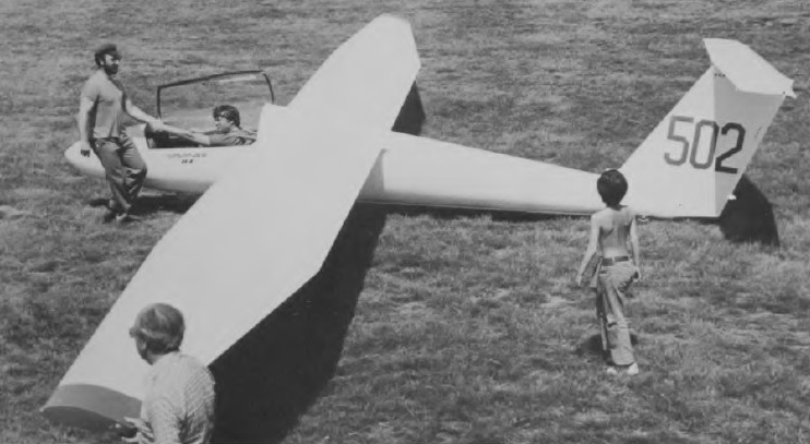
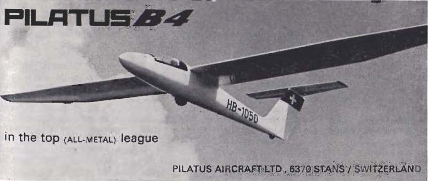
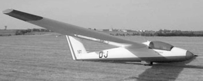
Pilatus B4 / Nippi B 4
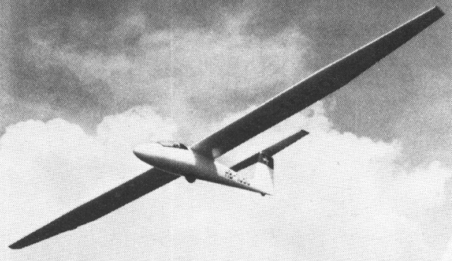
The only glider manufactured by Swiss aircraft manufacturer. First flying in 1972 the Pilatus B4 is an all-metal design to Standard Class specifications. It has full aerobatic capability including inverted maneuvers.
The B4 is a cantilever shoulder-wing monoplane with a T tail; the wings are of light alloy with a U-shaped light alloy main spar and hard PVC foam ribs between the metal ribs; the large skin panels are attached to the main spar by a single row of countersunk rivets, and the ailerons are of similar construction. There are light alloy spoilers in the wing upper surfaces at the 60% chord line. The semi-monocoque fuselage is also of light alloy, with a flush-riveted skin, and the rear fuselage consists of two half-shells riveted together. The light alloy T-tail has PVC ribs and a fixed-incidence tailplane, and the elevator has a bias spring for trimming. The landing gear consists of a non-retractable unsprung Tost monowheel with drum brakes, although a retractable one can be fitted if the customer desires, and there is a fixed tailwheel; small doors enclose the monowheel when retracted. The pilot sits in a semi-reclining position under a sideways-hinging canopy that is jettisonable in flight, and a battery radio and oxygen system are optional.
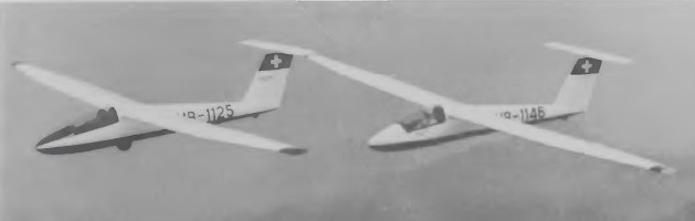
Certification for full aerobatic manoeuvres was granted in January 1975. Of all-metal construction, the type was designed by Ingo Herbot as a private venture and first flew in prototype form, as the B-4, in 1966; the design was taken over and developed by Pilatus as the B4-PC11, which first flew in 1972. Swiss certification was granted on 12 June that year, and the first delivery was made shortly afterwards. Seventy eight B 4s were sold in 1977, and 320 were in operation.
More than 330 examples of the Standard Class Swiss single-seater had been delivered to customers in no less than 30 countries by March 1978, and the production rate was as high as 7-8 aircraft per month.
On 19 June 1978 Pilatus announced the sale of all manufacturing and sales rights in the B4 to the Japanese firm of Nippi – Nihon Kikoki Kabushiki Kaisha (or Japan Aircraft Manufacturing Co Ltd) so as to be able to concentrate on production and development of the PC-6 Turbo-Porter and PC-7 Turbo-Trainer.
The first Nippi-built B4-PC11 AF was rolled out on 1 June 1979 and initial production was to be at three per month after Japanese certification. The first Nippi-built B4-PC11 AF made its maiden flight on 25 November 1979. Pilatus was to continue the product support of Swiss-built examples.
Number of aircraft built to 6/30/81 400.
Pilatus B4
Wing span: 49 ft 2.5 in
Length: 21 ft 6.5 in.
Seats: 1
Wing loading: 5.13 lb/sq.ft.
Aspect ratio: 16.1
Max TO wt: 770 lb.
Empty wt: 506 lb
Useful load: 264 lb.
Max speed: 130 kt
Rough air speed: 130 kt.
Stall: 30 kt
Lift to drag: 35 @ 46 kt.
Sink: 2.1 fps @ 39 kt.
B4-PC11
Wing span: 15.0 m / 49 ft 2.5 in
Length: 6.57 m / 21 ft 6.5 in
Height: 1.57 m / 5 ft 1 in
Wing area: 14.04 sq.m / 151.1 sq ft
Wing section: NACA 643 618
Aspect ratio: 16.0
Empty weight: 230 kg / 507 lb
Max weight: 350 kg / 772 lb
Water ballast: None
Max wing loading: 24.93 kg/sq.m / 5.1 lb/sq ft
Max speed: 129.5 kt / 240 km/h
Stalling speed: 33.5 kt / 62 km/h
Min sinking speed: 0.64 m/sec / 2.1 ft/sec at 39 kt / 72 km/h
Max rough air speed: 129.5 kt / 240 km/h
Best glide ratio: 35 at 46 kt / 85 km/h
B4-PC11AF
Wing Span: 15m / 49.2ft
Wing Area: 14.04sq.m / 151.1sq.ft
Length: 21 ft 7in
Height: 5 ft 2 in.
Empty Weight: 230kg / 506lb
Payload: 120kg / 264lb
Gross Weight: 350kg / 770lb
Wing Load: 24.93kg/sq.m / 5.13lb/sq.ft
Min Sink @ 39 kts / 45 mph: 0.64 m/s / 2.1 fps / 1.24 kt
L/D Max: 35 @ 85 kph / 46 kt / 53 mph
Max speed: 129 kts / 149 mph (in smooth air)
Stall speed: 33 kts.
Rough air airspeed: 86 kts
Max aero-tow speed: 112 mph
Airfoil: NACA 64(3)-618
Aspect ratio: 16.1
Seats: 1
Pilatus
Pilatus Flugzeugwerke AG
Pilatus Aircraft Ltd
Formed as Pilatus Flugzeugwerke AG in 1939, as a subsidiary of the Oerlikon armaments company. First aircraft was SB-2 Pelican six-seat light transport of 1944, but prototype only built. Followed by P-2 advanced trainer, produced in quantity for the Swiss Air Force in late 1940s, and the P-3 advanced trainer from 1953. Series production of the P-3 followed for the Swiss Air Force, and six went to the Brazilian Navy. In May 1959 Pilatus flew the first PC-6 Porter STOL monoplane with a Lycoming piston engine; this type has been in continuous production ever since, later developments using Astazou, Garrett, and most recently Pratt & Whitney Canada PT6A turboprop engine as the PC-6/B2-H4 Turbo Porter. Pilatus also signed a license agreement for production of Turbo Porters by Fairchild-Hiller in U.S.A. Also undertook Mirage production and maintenance work for the Swiss Air Force.
Became known as Pilatus Aircraft Ltd, based at Stans, Switzerland,.the product range encompassing the PC-7 Turbo Trainer (first flown August 1978 in production form), PC-7 Mk II (M) Turbo Trainer (first flown September 1992), the PC-9 (M) Advanced Turbo Trainer (first flown May 1984) with the highest engine power of the range and also selected in 1995 for U.S. military service as the Raytheon/Beech T-6A Texan II, and the PC-12 utility and business turboprop transport (first flown May 1991 and also available in military form). Also, in 1979 Pilatus took control of the LJ.K.’s Britten-Norman Ltd company, becoming Pilatus Britten-Norman, but sold this company in July 1998.
Pilatus Aircraft Ltd., the Swiss aircraft manufacturer, has sold all manufacturing and marketing rights to the B 4 all metal, aerobatic glider to Nippi, Japan Aircraft Manufacturing Company. The glider license was sold because of a lack of space in the Pilatus factory, where much room is devot¬ed to production of the PC 7 Turbo Trainer. Seventy eight B 4s were sold in 1977, and 320 were in operation. The first Japanese airplanes were expected in April 1979.
The take-over of the assets of Britten-Norman by Pilatus Aircraft was finalised on 34 January 1979 when the necessary documents were signed. To conclude the deal, Pilatus – itself a member of the Oerlilon-Buehrje Group – set up a British subsidiary, Pilatus Britten-Norman Ltd, and this company has acquired the B-N assets which include the Bembridge factory, the complete Islander / Trilander production hardware (plus stock materials) located at the Fairey SA factory in Gosselies, Belgium and the exclusive production and marketing rights for all Britten-Norman products.
In July 1998 Pilatus sold Britten-Norman to private investment company Litchfield Continental Ltd.
