2009: Hofener Weg 72582 Grabenstetten Germany
Glider builder
2009: Hofener Weg 72582 Grabenstetten Germany
Glider builder

Wing span: 15 m
Wing area: 10.9 sq.m
Empty Weight: 235 kg
Gross Weight: 350 kg
Wing Load: 32.1 kg/sq.m
Aspect ratio: 20.64
Airfoil: FX 61-163
L/DMax: 35 88 kph
MinSink: 0.65 m/s 70 kph
Seats: 1
Built: 70
Structure: GFK
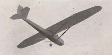
The “Kacha” (Russian: Степанчонок “Кача”) was designed by pilot Vasili Andreyevich Stepanchonok in 1930, during his time as an instructor at the Kacha flight school in Sevastopol.
The “Kacha” was designed as a cantilever high-wing glider. The wing had a double wooden spar structure and was covered with plywood sheets up to the position of the second spar. From there the covering was made of fabric.
The wide, angular fuselage featured a duralumin nose with the rest in plywood-coated wood. The bow area featured a removable aluminum deck. At the rear of the cabin there was another one made of plywood. A towing hook with release system was installed in the first frame of the fuselage.
The landing gear consisted of a central wheel with steel sheet.
The “Kacha” glider was completed in 1930 and his main purpose was to serve as a trainer at the Kacha Higher Flight School. It was presented without great success in the VII National Sailing Competitions, held in 1930 in Koktebel .
Despite the great wing aspect ratio (18.7), the good finish and the excellent construction lines, the flight characteristics of the “Kacha” were quite poor. This was largely due to the poor selection of the TsAGI-311 wing profile, of a high relative thickness and the poor aerodynamic shape of the wide fuselage, with resistance surfaces perpendicular to the air flow.
Kacha
Wingspan: 16.20 m
Wing area: 14.00 m²
Aspect ratio: 18.7
Length: 5.55 m
Empty weight: 150 kg
Wing loading: 16.4 kg / m²
Surface of the horizontal planes: 3.16 m²
Elevator area: 1.74 m²
Rudder surface area: 0.87 m²
Accommodation: 1
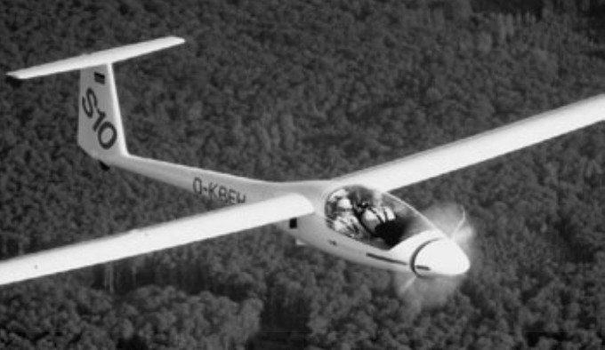
A two seat, side-by-side, motor-glider designed by Reiner Stemme, first flown in 1986, and first produced in 1990 at the Stemme factory at Strausberg Airfield, east of Berlin. The fuselage has a central steel tube frame, which forms the attachments for the wings, undercarriage and fixed internal powerplant. The carbon fibre rear fuselage bolts onto this frame, and the cockpit sec¬tion, which is a Kevlar lined carbon fibre shell, fits on the front. It has an electrically retractable undercarriage; not the conven¬tional glider mono wheel, but the more con¬ventional powered aircraft variety (although the track is quite narrow at 1.15 m). The engine is mounted behind the cockpit with a carbon shaft running through a Kevlar tunnel to a folding prop located behind a large retracting nose cone.
There are three basic varia¬tions of the Stemme, the S10, the S10V and the S10VT. The S10 has a four cylinder 93 hp Limbach four-stroke engine powering a fixed-pitch propeller. This combination gives a cruise speed of 90 knots. The S10V uses the same engine but with a variable-pitch propeller, giving a higher cruise speed of 121 knots.
The S10VT utilises a 115 hp turbocharged Rotax 914 engine, which gives a cruise speed of 140 knots at 10,000 ft. All variations a have a 23 m wingspan and can achieve a glide ratio of 50:1 while accommodating a crew of two. The three piece, 23 metre span, folding wings, contain two 45 litre fuel tanks.
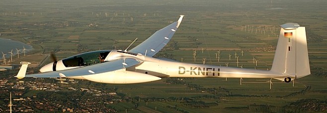
The S 10 VT engine, a 115 horsepower Rotax 914 Turbo (thus the “T” in the designation) with water cooled heads and a dual ignition system, is located in the lower fuselage be¬hind the cockpit. A centrifugal clutch turns a carbon fibre driveshaft, which is encased in a Kevlar tunnel and runs through the cen¬tral console to a reduction gearbox (0.9: 1) mounted behind the propeller in the nose section. The variable pitch (the “V” in the designation) folding propeller blades extend au¬tomatically by centrifugal force when the engine is started, with the nose cone mov¬ing forward and out of the way. When the engine is stopped, the blades fold inwards by a spring system and the nose cone is re¬tracted (which takes about six seconds) and the machine becomes a glider. The two-seater has carbon-fiber wings and solar panels for 30W of electrical power once airborne.
No. Built: 60
The U.S. Air Force Academy operates 2 S 10’s as the TG-11 A model (S 10VT), 94-1400 and 94-1500 also as civil N94FT and N94FW.
S10
Engine: 69 kW/ 93 bhp Limbach L2400 EB1. D
Wing span: 23m / 75.46 ft
Wing area: 18.74sq.m / 201.7sq.ft
Aspect ratio: 28.22
Airfoil: HQ-41
Empty Weight: 635kg / 1400lb
Payload: 215kg / 474lb
Gross Weight: 850kg / 1874lb
Wing Load: 45.39kg/sq.m / 9.29lb/sq.ft
Cruise: 90 kts
L/DMax: 51
MinSink: 0.56 m/s / 1.83 fps / 1.08 kt
Structure: GFRP/ CFRP/ Kevlar/ Steel tube
Seats: 2
S10V
Engine: Limbach, 93 hp
Prop: variable pitch
Wing span: 23m / 75.46 ft
Wing area: 18.74sq.m / 201.7sq.ft
Aspect ratio: 28.22
Airfoil: HQ-41
Cruise: 121 kts
S10
Engine: Rotax 914, 115 hp
Wing span: 23m / 75.46 ft
Wing area: 18.74sq.m / 201.7sq.ft
Aspect ratio: 28.22
Airfoil: HQ-41
Cruise: 140 kts
The company Stemme was founded in 1984 by Reiner Stemme specifically to develop and construct the S10 VT motor glider type.
Wing Span: 10.4m
Wing Area: 11.4 sq.m
Empty Weight: 245 kg
Gross Weight: 340 kg
Wing Load: 29.8 kg/sq.m
Aspect ratio: 9.49
Airfoil: FX 71-L-150/20
Min Sink: 0.8m/s
L/D Max: 26
No. Built: 1
Seats: 1
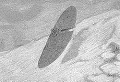
Swiss pioneer Carl Steiger-Kirchhofer (1856-1946) made some flights with this parabolic wing tail-less glider in 1891.
Swiss pioneer Carl Steiger-Kirchhofer (1856-1946) made some flights with this parabolic wing tail-less glider in 1891. In the same year he published the booklet “Vogelflug und Flugmaschine”, in which he proposed several very designs with surprisingly modern-looking features. He continued with other projects, such as a 1908 underpowered biplane and several studies of bird flight and bird models, including wind tunnel experiments.
The Stedman TS-1 City of Leeds was a two-seat tandem sailplane designed and built by R.F. Stedman in Leeds, UK, in 1932. It was first flown on 21 July 1934 at Baildon, UK. It became BGA.213 and survived the war.
.
Wingspan: 50 ft
Wing chord: 6 ft
Wing area: 295 sq.ft
Weight: 424 lb
Wing loading: 2-2.48 lb/sq.ft
Seats: 2

One other military aircraft project was undertaken by St. Louis Aircraft during the Second World War. Having already placed large-scale aircraft production contracts with the major airframe builders, the Army sought to employ secondary sources when it decided in 1941 to develop a significant glider assault capability. Not being burdened at the time with aircraft production contracts, St. Louis Aircraft was invited to participate in the Army’s glider program, obtaining contracts to develop eight-place and fifteen-place troop-carrying gliders. The eight-place XCG-5 demonstrated serious aerodynamic flaws during its first test flights (at Lambert Field) in 1942. The redesign necessary to correct the aerodynamic, as well as significant structural, problems doomed the XCG-5. The larger, heavier XCG-6 was never built.
