Cramlington Aircraft Camcraft 1

A single-seat primary glider designed and built by Cramlington Aircraft Ltd, Northumberland. Conventional wooden construction, it featured easy dismantlement. The fuselage consisted of a rigid boom to tail-unit. Originally designed with a wing chord of 5 ft, this was reduced to 4 ft 6 in as a cost reduction.

The undercarriage was a main skid only. The wing was wire braced with no flaps or airbrakes.

The price in 1930 was £55.

Specifications published in a 1930 ‘Sailplane and Glider’ gave a wingspan of 10.21 m / 33 ft 6 in, and length of 5.18 m / 17 ft 0 in.

Later specifications given were;
Wingspan: 10.41 m / 34 ft 2 in
Length: 5.58 m / 18 ft 3.5 in
Wing area: 14.21 sq.m / 153 sq.ft
Aspect ratio: 7.6
Empty weight: 63.5 kg / 140 lb
Seats: 1

Cramlington Aircraft Ltd

Cramlington
Northumbeland
UK

The directors were Lrslie Runcimam, President of the Newcastle and Teesside Gliding Club. And Miss Constance Leathart.

A few primary gliders of an original design were built by the company in 1930 and 1931 at Cramlington. The firm was principally a repair and service organisation, and it carried out all of the C of A work for the Newcastle Aero Club, but went out of business shortly after the Aero Club moved to Woolsington Aerodrome.

Costello Flapper

Australian Ron Costello, 46, of Victoria, designed and built this pedal-powered flapper in 1964. The tail is controlled ‘string’, with the pilot standing on a narrow platform.

Costello worked for the Civil Aviation Department and government buddies notified him officially by letter that man-powered craft don’t always work.

Cornelius XFG-1

The 677 gal (2,563 l) experimental fuelling glider XFG-1 incorporated Cornelius’ experience with swept-forward wings and was intended to be towed (by a Douglas C 47) pilotless with the controls locked. After the fuel was transferred to the towplane, it was to be cast off and abandoned. An alternative use was as a piloted fuel carrier, jettisoning its undercarriage after take-off, and landing at its destination on two skids at the bottom of the fuselage.

Basically a flying fuel tank, the forward swept wings were mounted behind the cylindrical fuel tank forming the fuselage centre section. The incidence of the XFG-1 wing was adjustable on the ground at 3°, 5° and 7°. With a swept-forward wing, an increase in incidence raises the wingtips and produces dihedral, which may explain why some accounts describe the adjustment as variable-dihedral.

Two were produced for the USAAF in 1945 by the Spartan Aircraft Corporation at Tulsa, Oklahoma, under the serials 44-28059, 44-28060. Thirteen flights were made in prototype 44-28059 by Reitherman, on the last of which he was killed after failing to recover from a spin. The second machine, 44-28060, made 19 flights, but work was discontinued with the end of WW II.

Cordas SCS-1

Designed by A. C. Cordas, the SCS-1 features a V-tail, spoilers in a hatch aft of the canopy and a 3-piece wing.

Wingspan: 13.41m/ 44ft
Wing Area: 12.31 sq.m / 132.5 sq.ft
Empty Weight: 148 kg /326lb
Payload: 102kg / 224lb
Gross Weight: 250kg / 550lb
Wing Load: 20.31 kg/sq.m / 4.15 lb/sq.ft
Aspect ratio: 14.6
Airfoil: NACA 33012
L/DMax: 30 at 88 kph/ 49 kt/ 55 mph
MinSink: 0.67 m/s / 2.2 fps / 1.3 kt
No. Built: 1
No. of Seats: 1

Corcoran 65-1

The 65-1 was designed and built by R. S Corcoran, an experienced sailplane pilot who was also the president of a company bearing his name which manufactured centrifugal pumps and other products. The 65-1 single-seater first flew in prototype form in October 1965, the powerplants being two 8hp West Bend 820 single-cylinder go-kart engines mounted on small booms extending from aft of the cockpit, and driving two-blade fixed-pitch pusher propellers. Construction is all-metal, the single-spar wings having aluminium skinning and unbalanced piano-hinged ailerons; the upper wing has flaps along 60% of its span which can be lowered to four positions, the maximum deflection being 35°. There is a single interplane strut and bracing strut on each side. The slab-sided fuselage is built up from aluminium extrusions and is also covered with aluminium; the landing gear consists of a monowheel mounted in an under-fuselage fairing, a steerable tailwheel and two small outrigger balancing wheels under the lower wings below the interplane struts – these are actually Sears ballbearing lawnmower wheels. The pilot sits under a single-framed cockpit canopy that hinges to port for entry and exit. The prototype 65-1 had a wing area of 100sq ft and was followed by a second prototype with a wing area increased to 180sq ft and two engines mounted inboard in the fuselage and driving belt-driven propellers mounted on outriggers.

First Prototype
Span: 26 ft 0 in
Length: 18 ft 6 in
Height: 5 ft 0 in
Wing area: 100 sqft
Aspect ratio: 13.0
Empty weight: 364 lb
Max weight: 550 lb
Max speed: l00 mph (power on)
Cruising speed: 67 mph
Take-off run: 500 ft
Range: 140 miles

Colditz Cock

The town of Colditz in eastern Germany is the home of Oflag IV-C, the most secure prison camp in the Third Reich. Housed in an 11th Century castle, 500 Allied officers – including Sir Douglas Bader and SAS founder David Stirling – had little chance of escape.

The castle walls were more than 6ft thick and prisoners’ cells were built around a central courtyard, its only exit blocked by three sets of heavily guarded gates. There was one guard for every prisoner.

Tunnelling seemed impossible because the castle sat on an outcrop of volcanic rock. Even so, Allied prisoners made 186 escape attempts before the camp was liberated on April 16, 1945. The first of 11 Britons to make a ‘home run’ was former Northern Ireland Secretary Airey Neave, who disguised himself as a German officer and walked out of the camp during a theatrical production through a trap door prisoners built under the stage.

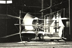
They managed to construct a glider designed by W.Goldfinch, from materials including bedsteads, floorboards, cotton sheets and porridge. Sixteen British prisoners had built the two-man glider behind a false wall in the prison attic, in a space just 20ft by 7ft. Forty more acted as lookouts. ‘Forty guys collected their rations during the period of the project to glue the glider together,’ said Tony Hoskins, the engineer in charge of the reconstruction.

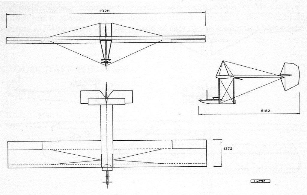
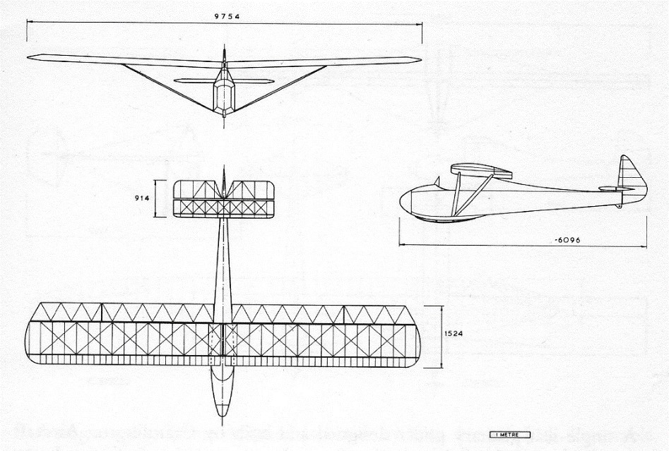
They fashioned tools from bedsteads and iron window bars and made the wing spars from floorboards, the glider skin from cotton sheets and the control wires from electric cable. The finished glider spanned 33ft 9in and was 19ft 7in long.

The prisoners planned to construct a runway on the castle’s sloping roof. The idea was to knock a hole through the roof from their workshop under cover of darkness. They were then going to haul the glider out and attach its wings before launching from the runway by catapulting it with the aid of a bathtub, weighted down with concrete.

The glider, though, was never tested because the castle was liberated by the Americans before the prisoners had a chance to try.

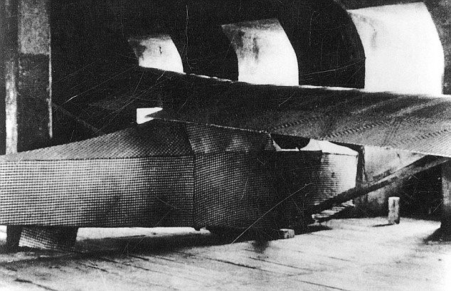
Only one photograph and one crude A4 sketch exists of the glider, which townspeople believe was burnt as firewood.

But engineers and historians have long questioned whether their two-man machine would actually fly. It left the question of could British prisoners have succeeded in their attempt to fly off the roof of the Colditz Castle and make their escape in a glider?

In 2012, a Channel 4 crew created a replica in the attic where it was originally conceived – from similar materials with modern tools. They were able to complete it in two weeks, compared with the ten months it took the prisoners.

The replica glider cost £3,500 in materials, including 27 sheets of pine wood, ten 16ft lengths of beech and 525ft of gingham. It was assembled with 700 panel pins, 300 wooden screws and door and window hinges. The ‘skin’ of the original glider had been starched with a ‘porridge’ made from the prisoners’ rations. The engineers copied the original mixture, which was made from millet seed. The hardest thing for us was that there was no formula for the porridge. They started with 22lb of millet in a big pot and tried every method and consistency until they got it right.

The original glider was built to carry two prisoners, but in 2012 a polystyrene dummy, nicknamed Alex, sat in the cockpit while the aircraft was steered by remote control.

D-Day for the replica Colditz glider came on March 17 2012. The team gathered at 5.45am to assemble the glider on the platform on the apex of the castle roof. The fuselage, tail, rudder and wings, wrapped in a fabric sling for protection, were all lifted individually round the clock tower and on to the roof using a system of ropes.

Amid the sound of chapel bells and rousing cheers from spectators, including the Mayor of Colditz, Matthias Schmiedel, and the German aviation official who signed off the flight, the glider finally rose into the sky at 2.30pm and achieved its first goal – it flew, crossing the River Mulde.

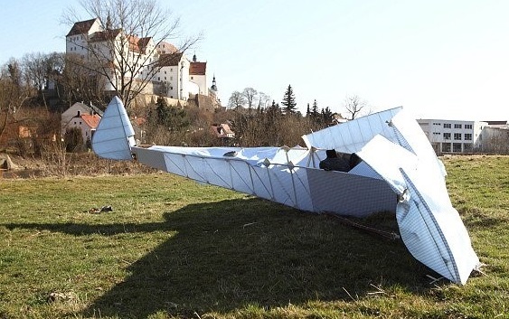
Travelling at 36mph, it then swooped down along the river before turning steeply and crash landing – wing tip first – in the middle of a field after flying 984ft.

‘She came off there like a treat,’ said Pat Willis, 53, who controlled the military-standard radio transmitter. ‘The crash landing was deliberate. I was running out of space so I dumped the glider about 50ft short. There was no way I was going to go through people’s property.’

The flight was monitored on a live video link from the cockpit. ‘We’ve proved that the concept worked,’ said Mr Hoskins. ‘We launched it and it had ample speed as it left the roof. The problem was on arrival. The rudder was fairly ineffective, so when it went to instigate a right-hand turn it was very slow in coming round.

Alexander, the polystyrene dummy, was decapitated.

Wingspan: 9.75 m / 32 ft 0 in
Length: 6.10 m / 20 ft 0 in
Wing areaL 15.05 sq.m / 162 sq.ft
Aspect ratio: 6.4
Wing section: Clark Y-H
Empty weight: 108.86 kg / 240 lb
AUW: 254.02 kg / 560 lb
Wing loading: 16.84 kg/sq.m / 3.45 lb/sq.ft
Max L/D: 12
Stall: 50 kph / 31 mph
Undercarriage: main skid

Cody Glider 

Turning his back on a 15 year stage career, Cody closed the road show and spent months on kite and airship matters. He built gliders in his spare time, but Cody was more interested in aeroplanes and before long had fitted a 12 h.p. Buchet engine to one of his kites.

The motor kite was constructed at Farnborough in 1907, though possibly started in 1906. It was a pilotless biplane, similar to a Cody kite but with additional control surfaces and a three-cylinder 12 hp Buchet engine powering a propeller situated behind the wings. The span of the upper wing is estimated to 35 feet. The undercarriage was fitted beneath the central box section and two long skids were mounted beneath the twin tail rudders. The machine had a horizontal tailplane and at one stage biplane elevators/balancing planes were fitted on the front.

It was tested both on the ground and suspended from a cable rigged between two 100 ft masts, but there is no evidence that it ever made a free flight. Cody said, when presenting slides of the machine to a meeting of the Aeronautical Society, “This is a kite; I am just starting the engine and I try to get out of the way to let it run. It was supposed to be let loose, but the authorities were afraid I might do some damage by letting it go up in the sky.”

Cody, Samuel F.

Born in Iowa, USA, in 1867 as Samuel Franklin Cowdery, he took on the name Cody to take advantage of the success of William Frederick ‘Buffalo Bill’ Cody of’Wild West’ fame. S F. Cody arrived in the UK in 1889 and set up a touring show. Part of the many ‘acts’ within this travelling ‘circus’ was the flying of substantial kites. Cody became fascinated by flight and developed his own cellular (or box) kites and in November 1902 patented his man-lifting design. The UK military became very interested in these devices as an observation system that was than cheaper and more efficient than balloons.

Samuel Cody Article

From 1906, Cody was appointed Chief Kite Instructor to the Balloon Factory at Farnborough, Hampshire. As well as kites, he assisted in the construction of the airship Nulli Secundus (Second to None) which first flew in September 1907, powered by a 50hp (37kW) Antoinette V8.
In 1908, Cody turned his attention to building a heavier-than-air flying machine inspired by the Wright Brothers’ designs. Fitted with the same Antoinette that had powered the airship, his British Army Aeroplane No.1 took to the air for the first time on October 16,1908, and put Cody into the history books. He became a British subject in October 1909.
He built another biplane in 1910 in which he took the Michelin Prize with a flight of 185 miles (297km) in a closed-circuit. He gained Royal Aero Club Aviator’s Certificate No.9 on June 7,1910.
Cody developed his Circuit of Britain Biplane in 1911, entering it for the Daily Mail 1,010-mile contest of the same name. He came fourth in that and won two Michelin Cups for close-circuit flying, becoming well known for flying passengers.
In 1912, he flew a short-lived tractor monoplane, which was destroyed in a collision with a cow that July. The same year saw the birth of the Military Trials Biplanes, which resulted in a pair being ordered for service with the Royal Flying Corps. (The second of these biplanes, No.304, was presented to the Science Museum in November 1913 and is today displayed at South Kensington, London.)
His final design was the large (even by Cody’s standards) Hydro-Biplane designed to enter the coastal Daily Mail Circuit of Britain of 1913. Cody and his passenger W H B Evans were killed in this machine, in landplane form, on August 7,1913. Pioneer Cody had become the 32nd British pilot fatality.